Ford Mondeo (petrol engines). Manual - part 107
spring must now be carefully released from
the compressor. If it is to be re-used, the
spring can be left in compression.
7 With the strut assembly now completely
dismantled, examine all the components for
wear and damage, and check the bearing for
smoothness of operation. Renew components
as necessary.
8 Examine the strut for signs of fluid leakage.
Check the strut piston for signs of pitting
along its entire length, and check the strut
body for signs of damage. Test the operation
of the strut, while holding it in an upright
position, by moving the piston through a full
stroke, and then through short strokes of 50
to 100 mm. In both cases, the resistance felt
should be smooth and continuous. If the
resistance is jerky, uneven, or if there is any
visible sign of wear or damage to the strut,
renewal is necessary.
9 Reassembly is a reversal of dismantling,
noting the following points:
(a) Make sure that the coil spring ends are
correctly located in the upper and lower
seats before releasing the compressor.
(b) Check that the bearing is correctly fitted
to the piston rod seat.
(c) Tighten the thrust bearing retaining nut to
the specified torque.
Removal
1 Apply the handbrake, jack up the front of
the vehicle and support it on axle stands.
Remove both front wheels.
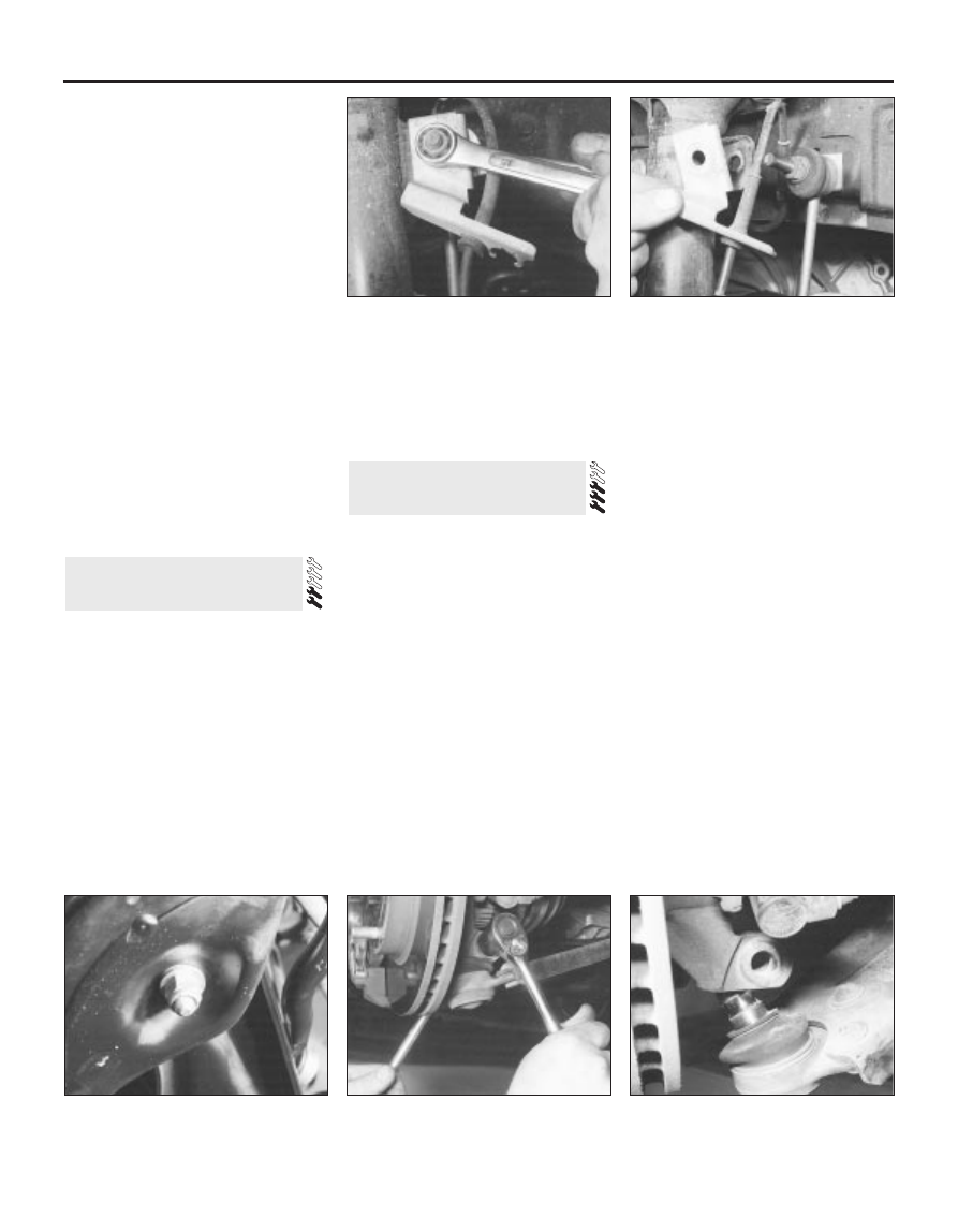
2 Unscrew the nuts, and disconnect the anti-
roll bar links from the front suspension struts
on both sides of the vehicle. Note that, on
models with ABS, the wheel sensor wiring
support brackets are located beneath the nuts
(see illustrations).
3 Unscrew and remove the anti-roll bar
mounting bolts from the engine subframe on
both sides of the vehicle.
4 Withdraw the anti-roll bar from one side of
the vehicle, taking care not to damage the
surrounding components.
5 If necessary, unscrew the nuts and remove
the links from the anti-roll bar.
Refitting
6 Refitting is a reversal of the removal
procedure.
Removal
1 Apply the handbrake, jack up the front of
the vehicle and support it on axle stands.
Remove the appropriate wheel.
2 If removing the right-hand side lower arm,
remove the auxiliary drivebelt cover where
necessary.
3 Unscrew and remove the nuts and bolts
securing the lower arm to the subframe (see
illustration).
4 Unscrew the nuts and disconnect the anti-
roll bar links from the anti-roll bar on both
sides. Swivel the anti-roll bar upwards away
from the lower arm.
5 Extract the split pin from the track rod end
balljoint nut. Unscrew the nut, and detach the
rod from the arm on the steering knuckle
using a conventional balljoint removal tool.
Take care not to damage the balljoint seal.
6 Remove the clip securing the driveshaft
inner gaiter to the inner CV joint, and
disconnect the gaiter from the CV joint
housing. This is necessary to prevent damage
to the gaiter when the steering knuckle is
moved outwards to remove the lower arm.
7 Note which way round the front suspension
lower arm balljoint clamp bolt is fitted, then
unscrew and remove it from the knuckle
assembly. Lever the balljoint down from the
knuckle; if it is tight, prise the joint open carefully
using a large flat-bladed tool. Take care not to
damage the balljoint seal during the separation
procedure. Support the inner end of the
driveshaft on an axle stand (see illustrations).
8 Remove the lower arm from the subframe,
and withdraw it from the vehicle.
Overhaul
9 Examine the rubber bushes and the
suspension lower balljoint for wear and
damage. The balljoint may be renewed as
described in Section 8. The rubber bushes
may be removed using a press, or a length of
metal tubing together with a long bolt,
washers and nut.
10 Note that the front and rear bushes are
different. The front one has a solid rubber
bush with a cylindrical inner tube, whereas the
rear one has a voided rubber bush with a
barrel-shaped inner tube (see illustration).
11 Press the new bushes into the lower arm,
using the same method as used for removal.
Note that, when fitting the rear bush, the voids
must be in line with the front bush location.
On later models, a pip on the rear bush must
be aligned with a triangular alignment mark on
the arm.
7 Front suspension lower arm -
removal, overhaul and refitting
6 Front anti-roll bar and links -
removal and refitting
10•8 Suspension and steering systems
6.2A Unscrew the nut . . .
6.2B . . . and disconnect the anti-roll bar
link and (on ABS models) the sensor wiring
support bracket
7.3 One of the nuts and bolts securing the
lower arm to the subframe
7.7A Unscrew the lower arm balljoint
clamp bolt . . .
7.7B . . . and disconnect the balljoint from
the knuckle