Ford Orion. Manual - part 42
 

  Index      Ford     Ford Orion - service and repair manual


Search            


Content   ..  40  41  42  43   ..


Ford Orion. Manual - part 42


18 Starter motor 

brush renewal

3

Remove the starter motor from the vehicle
as described in Section 17.

Bosch

Undo the two retaining screws and remove
the end cap (see illustrations).
Wipe free the grease from the end of the
armature shaft, then prise free and remove the
C-clip from the shaft groove. Depending on
the type fitted, remove the washer/spacer(s)
(see illustration).
Unscrew and remove the two through-

bolts, then remove the commutator end
plate/housing from the starter motor (see
illustration)
.
On the Bosch D-type starter motor,
disconnect the brush link lead from its
terminal stud (see illustration).
Withdraw the brush plate assembly (taking
care not to damage the terminal brushes),
then release the brushes from their holders in
the brush plate.
Clean and inspect the brush assemblies. If
the brushes have worn beyond (or down to)
the specified minimum length, they must be
renewed as a set. In the case of the D-type
motor, the complete brush plate unit will have
to be renewed. To renew the brushes on the
other types, the brush leads must be

unsoldered from the brush plate terminals,
and the new brush leads soldered in their
place.
Prior to refitting the brushes, check the
condition of the commutator face on which
they run. Wipe the commutator with a solvent-
moistened cloth. If the commutator is dirty, it
may be cleaned with fine glass paper, then
wiped with the cloth.
Fit the new brushes using a reversal of the
removal procedure. To ease fitting of the
brush assembly over the end of the
commutator, press the brushes back into their
holders, and insert a suitable socket or tube to
retain them. Align the socket with the end of
the commutator, and slide the brush
assembly from the socket onto the
commutator and into position as shown (see
illustration)
. Make sure that the brushes
move freely in their holders.

5•12 Engine electrical systems

18.9  Brush plate unit assembled over a

socket with the same outside diameter as

the commutator to ease assembly

18.5  Detach the brush link lead (Bosch D-

type starter motor)

18.4  Remove the commutator endplate

(Bosch starter motor)

18.2D  Remove the starter motor end cap

(Bosch starter motor)

18.3  Remove the C-clip and any washers

(Bosch starter motor)

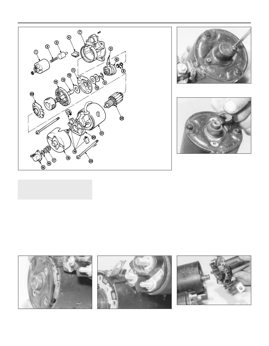
18.2C  Exploded view of the Bosch EV starter motor

1  Yoke
2  Return spring
3  Solenoid armature
4  Rubber block
5  Actuating arm
6  Drive pinion and 

clutch

7  End housing
8  C-clip and thrust 

collar

9  Circlip

10  Spacers
11  Cover plate
12  Spacer
13  Output shaft and 

planet gear unit

14  Ring gear
15  Commutator end 

housing cap

16  C-clip
17  Shims
18  End housing
19  Brushes
20  Brush plate
21  Yoke
22  Armature
23  Retaining plate
24  Through-bolt

Magneti-Marelli

10 Undo the two retaining screws, and
remove the end cap and seal (see
illustration)
.
11 Wipe free the grease from the end of the
armature shaft, then prise free and remove the
C-clip from the shaft groove. Remove the
spacer(s).
12 Unscrew the retaining nut, and detach the
connecting link from the solenoid.
13 Undo the two retaining screws, and
withdraw the solenoid yoke from the drive end
housing. Lift it upwards, and disengage the
solenoid armature from the actuation lever in
the end housing.
14 Unscrew and remove the two through-
bolts, then remove the commutator end
housing from the yoke and armature unit.
15 Detach the brush housing insulator, and
withdraw the brushes from the housing (see
illustration)
.
16 If the brushes have worn down to, or
beyond, the minimum length specified, they
must be renewed as a set. To renew them, cut
their leads at the mid-point, and make a
secure soldered joint when connecting the
new brushes.
17 Prior to refitting the brushes, check the
condition of the commutator face on which
they run. Wipe the commutator with a solvent-
moistened cloth. If the commutator is dirty, it
may be cleaned with fine glass paper, then
wiped with the cloth.
18 Fit the new brushes, and reassemble the
starter motor using a reversal of the removal
procedure. Make sure that the brushes move
freely in their holders. When fitting the armature
unit to the yoke, engage the actuating arm in
the drive end housing together with the plastic
bracket (locates in the notch in the yoke face)
and rubber block. Ensure that the drive end

Engine electrical systems  5•13

18.10  Exploded view of the Magneti-Marelli starter motor

18.15  Brush plate components - Magneti-Marelli M79 starter

motor

A  Brush plate
B  Brush plate insulator
C  Brush holders and springs

D  Brushes
E  Insulators
F  Brush link

18.19  Exploded view of the Nippondenso starter motor

A   Armature
B   Actuating lever
C   Roller

clutch/pinion unit

D   Lower thrust collar
E   C-clip

F   Solenoid
G   Upper thrust collar
H   Drive end housing
J   Main casing
K   Brush
L   Brush spring

M  Brush box
N   Brush box insulator
P   Commutator end

plate

Q   Through-bolts

5

1  Yoke
2  Solenoid armature
3  Actuating arm
4  Rubber pad
5  Plastic support block
6  Drive end housing
7  Thrust collar

8  Drive pinion and clutch
9  Armature

10  Yoke
11  Brush
12  Brush link
13  Brush plate
14  Brush holder and spring

15  Insulators
16  Brush plate insulator
17  Commutator end housing
18  Shims
19  C-clip
20  Cap

housing is correctly aligned before fully
tightening the retaining screws.

Nippondenso

19 Unscrew the two through-bolts, and
withdraw the commutator end plate from the
main casing (see illustration).
20 Remove the brush box insulator and the
brush box.

21 If the brushes have worn down to or
beyond the minimum length specified, they
must be renewed as a set. To renew them, cut
their leads at the mid-point, and make a
secure soldered joint when connecting the
new brushes.
22 Prior to refitting the brushes, check the
condition of the commutator face on which
they run. Wipe the commutator with a solvent-

moistened cloth. If the commutator is dirty, it
may be cleaned with fine glass paper, then
wiped with the cloth.
23 Make sure that the brushes move freely in
their holders, then reassemble the brush box,
insulator and the commutator end plate.
Ensure that the rubber block engages with the
cut-out in the end plate, then refit the through-
bolts to secure.

5•14 Engine electrical systems

6

Crankshaft speed/position sensor

Resistance  . . . . . . . . . . . . . . . . . . . . . . . . . . . . . . . . . . . . . . . . . . . . . . .

200 to 450 ohms

Camshaft position sensor

Resistance  . . . . . . . . . . . . . . . . . . . . . . . . . . . . . . . . . . . . . . . . . . . . . . .

200 to 900 ohms

Inlet air temperature sensor

Resistance:

At 0ºC  . . . . . . . . . . . . . . . . . . . . . . . . . . . . . . . . . . . . . . . . . . . . . . . . .

89 to 102 kilohms

At 20ºC  . . . . . . . . . . . . . . . . . . . . . . . . . . . . . . . . . . . . . . . . . . . . . . . .

35 to 40 kilohms

At 100ºC  . . . . . . . . . . . . . . . . . . . . . . . . . . . . . . . . . . . . . . . . . . . . . . .

1.9 to 2.5 kilohms

At 120ºC  . . . . . . . . . . . . . . . . . . . . . . . . . . . . . . . . . . . . . . . . . . . . . . .

1.0 to 1.4 kilohms

Throttle position sensor

Resistance - see text  . . . . . . . . . . . . . . . . . . . . . . . . . . . . . . . . . . . . . . .

400 to 6000 ohms

Power steering pressure switch

Resistance:

Contacts open  . . . . . . . . . . . . . . . . . . . . . . . . . . . . . . . . . . . . . . . . . .

Infinite resistance

Contacts closed  . . . . . . . . . . . . . . . . . . . . . . . . . . . . . . . . . . . . . . . . .

0 to 2.5 ohms

Charcoal canister-purge solenoid valve

Resistance  . . . . . . . . . . . . . . . . . . . . . . . . . . . . . . . . . . . . . . . . . . . . . . .

50 to 120 ohms

Pulse-air solenoid valve

Resistance  . . . . . . . . . . . . . . . . . . . . . . . . . . . . . . . . . . . . . . . . . . . . . . .

50 to 120 ohms

Torque wrench settings

Nm

lbf ft

Camshaft position sensor screw  . . . . . . . . . . . . . . . . . . . . . . . . . . . . . .

18 to 23

13 to 17

Inlet air temperature sensor  . . . . . . . . . . . . . . . . . . . . . . . . . . . . . . . . . .

23

17

Oxygen sensor  . . . . . . . . . . . . . . . . . . . . . . . . . . . . . . . . . . . . . . . . . . . .

60

44

Pulse-air system piping-to-exhaust manifold sleeve nuts  . . . . . . . . . . .

32

24

Chapter 6 Emissions control systems

Catalytic converter - general information and checking   . . . . . . . . .

8

Catalytic converter - removal and refitting  . . . . . . . . .

See Chapter 4

Electronic control systems - description and precautions  . . . . . . . .

2

Engine compartment wiring check  . . . . . . . . . . . . . . .

See Chapter 1

Evaporative emissions control (EVAP) system   . . . . . . . . . . . . . . . . .

5

Exhaust system check  . . . . . . . . . . . . . . . . . . . . . . . .

See Chapter 1

General information . . . . . . . . . . . . . . . . . . . . . . . . . . . . . . . . . . . . . .

1

Information sensors - general information, testing, removal 

and refitting  . . . . . . . . . . . . . . . . . . . . . . . . . . . . . . . . . . . . . . . . . .

4

Positive Crankcase Ventilation (PCV) system   . . . . . . . . . . . . . . . . .

7

Positive Crankcase Ventilation (PCV) system checking and 

filter cleaning . . . . . . . . . . . . . . . . . . . . . . . . . . . . . .

See Chapter 1

Pulse-air system - general information, checking and component 

renewal  . . . . . . . . . . . . . . . . . . . . . . . . . . . . . . . . . . . . . . . . . . . . .

6

Self-diagnosis system - general information . . . . . . . . . . . . . . . . . . .

3

Underbonnet hose check  . . . . . . . . . . . . . . . . . . . . . .

See Chapter 1

6•1

Easy, suitable for
novice with little
experience

Fairly easy, suitable
for beginner with
some experience

Fairly difficult,
suitable for competent
DIY mechanic

Difficult, suitable for
experienced  DIY
mechanic

Very difficult,
suitable for expert
DIY or  professional

Degrees of difficulty

Specifications

Contents


Content   ..  40  41  42  43   ..