Ford Orion. Manual - part 40
5
Ignition system - testing
2
Warning: Because of the high
voltage generated by the ignition
system, extreme care should be
taken whenever an operation is
performed involving ignition components.
This not only includes the ignition module,
coil and spark plug (HT) leads, but related
components such as electrical connectors,
tachometer and other test equipment also.
Note: This is an initial check of the “ignition
part” of the main engine management system,
to be carried out as part of the preliminary
checks of the complete engine management
system (see Chapter 6).
1 If the engine turns over but won’t start,
disconnect the (HT) lead from any spark plug,
and attach it to a calibrated tester (available at
most automotive accessory shops). Connect
the clip on the tester to a good earth - a bolt
or metal bracket on the engine. If you’re
unable to obtain a calibrated ignition tester,
have the check carried out by a Ford dealer
service department or similar. Any other form
of testing (such as jumping a spark from the
end of an HT lead to earth) is not
recommended, because of the risk of
personal injury, or of damage to the ignition
module (see notes above and in Section 4).
2 Crank the engine, and watch the end of the
tester to see if bright blue, well-defined sparks
occur.
3 If sparks occur, sufficient voltage is
reaching the plug to fire it. Repeat the check
at the remaining plugs, to ensure that all leads
are sound and that the coil is serviceable.
However, the plugs themselves may be fouled
or faulty, so remove and check them as
described in Chapter 1.
4 If no sparks or intermittent sparks occur,
the spark plug lead(s) may be defective -
check them as described in Chapter 1.
5 If there’s still no spark, check the coil’s
electrical connector, to make sure it’s clean
and tight. Check for full battery voltage to the
coil at the connector’s centre terminal. Check
the coil itself (see Section 6). Make any
necessary repairs, then repeat the check again.
6 The remainder of the system checks should
be left to a dealer service department or other
qualified repair facility, as there is a chance
that the ignition module may be damaged if
tests are not performed properly.
6
Ignition coil - checking,
removal and refitting
2
Warning: Because of the high
voltage generated by the ignition
system, extreme care should be
taken whenever an operation is
performed involving ignition components.
This not only includes the ignition
module/ECU, coil and spark plug (HT)
leads, but related components such as
electrical connectors, tachometer and
other test equipment also.
Check
1 Having checked that full battery voltage is
available at the centre terminal of the coil’s
electrical connector (see Section 5),
disconnect the battery negative (earth) lead -
see Section 1.
2 Unplug the coil’s electrical connector, if not
already disconnected.
3 Using an ohmmeter, measure the
resistance of the coil’s primary windings,
connecting the meter between the coil’s
terminal pins as follows. Measure first from
one outer pin to the centre pin, then from the
other outer pin to the centre. Compare your
readings with the coil primary resistance listed
in the Specifications Section at the beginning
of this Chapter.
4 Disconnect the spark plug (HT) leads - note
their connections or label them carefully, as
described in Chapter 1. Use the meter to
check that there is continuity (ie, a resistance
corresponding to that of the coil secondary
winding) between each pair of (HT) lead
terminals; Nos 1 and 4 terminals are
connected by their secondary winding, as are
Nos 2 and 3. Now switch to the highest
resistance scale, and check that there is no
continuity between either pair of terminals and
the other - ie, there should be infinite
resistance between terminals 1 and 2, or 4
and 3 - and between any terminal and earth.
5 If either of the above tests yield resistance
values outside the specified amount, or
results other than those described, renew the
coil. Any further testing should be left to a
dealer service department or other qualified
repair facility.
Removal
6 Disconnect the battery negative (earth) lead
(refer to Section 1).
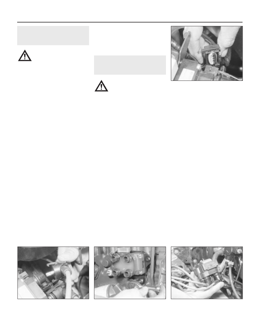
7 Disconnect the coil main electrical
connector and (where fitted) the electrical
connector to the suppressor (see
illustration).
8 The coil can be removed with the HT leads
left attached, in which case disconnect the
leads from their respective spark plugs and
from the location clips in the rocker cover or
air inlet duct (as applicable). If preferred, the
HT leads can be disconnected from the coil.
First check that both the ignition HT leads and
their fitted positions are clearly marked
numerically to ensure correct refitting. Spot
mark them accordingly if necessary, using
quick-drying paint.
9 If disconnecting the leads from the spark
plugs, pull them free by gripping on the
connector, not the lead. To detach the leads
from the ignition coil, compress the retaining
arms of each lead connector at the coil, and
detach each lead in turn (see illustration).
10 Unscrew the Torx-type retaining screws,
and remove the coil from its mounting on the
engine (see illustrations).
5•4 Engine electrical systems
6.10B Removing the ignition coil from the
CVH engine (leaving the HT leads attached)
6.10A Unbolting the ignition coil from the
HCS engine
6.9 Disconnecting an HT lead from the
ignition coil (CVH engine shown)
6.7 Disconnecting the multi-plug from the
ignition coil