Ford Orion. Manual - part 38
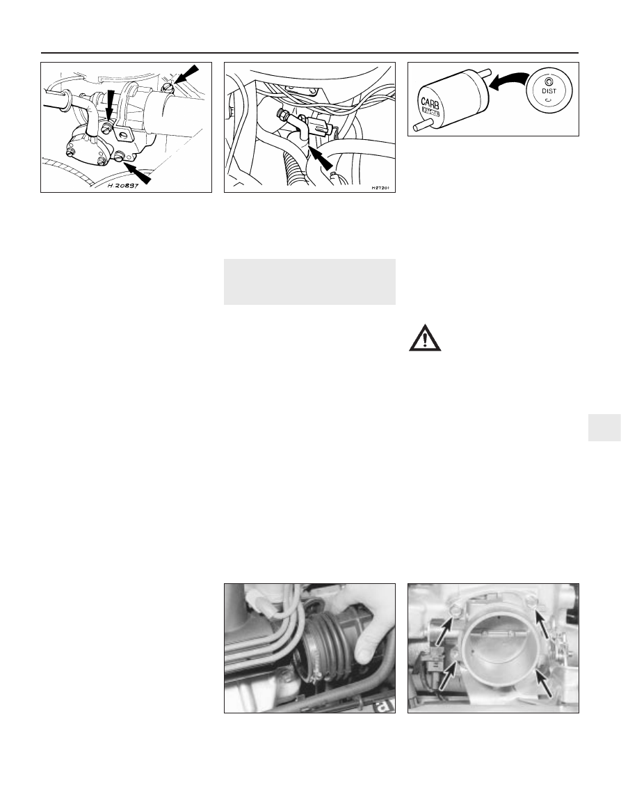
34 Refer to Section 4 and remove the air
cleaner.
35 Detach the wiring multi-plugs from the
throttle position sensor and the throttle plate
control motor, and release the retaining clips
on the bracket (see illustrations).
36 Undo and remove the motor support
bracket screws, and remove the bracket
complete with the motor from the CFi unit
(see illustration).
37 Undo the motor retaining screws and
remove it from the support bracket.
38 Refit in the reverse order of removal, but
note the following points:
a)
When refitting the motor and its support
bracket to the injector unit, the throttle
position sensor must locate on the
accelerator linkage, and the bracket must
align with the pegs.
b)
On completion, the idle speed should be
checked by a Ford garage or fuel injection
specialist who has the required
equipment to link up with the engine
management ECU.
Fuel trap
Check
39 A fuel trap is fitted to the Manifold
Absolute Pressure (MAP) sensor hose (see
illustration).
40 Disconnect the vacuum hose between the
MAP sensor and the inlet manifold, and check
carefully for any sign that fuel may be present
in the hose. Remove both hoses from the fuel
trap, and blow out both with compressed air.
Ensure that when in its fitted position there
are no dips in the hose, and that it does not
chafe against any components or wiring. Note
that if fuel was found to be present in the
vacuum hose, it is possible that the MAP
sensor may have been contaminated; this
component should be tested by a Ford dealer
using specialist equipment.
Renewal
41 To renew the fuel trap, first disconnect the
battery negative (earth) lead (refer to Chap-
ter 5, Section 1), then disconnect the vacuum
hoses from the fuel trap and withdraw it.
42 Refit in the reverse order of removal. It is
important to ensure that the trap is correctly
orientated, with the “CARB” mark on one end
face towards the inlet manifold, and the
“DIST” mark towards the MAP sensor (see
illustration).
16 Fuel injection system
components (1.6 litre EFi) -
checking and renewal
3
Warning: The fuel system pressure must
be released before any part of the system
is disturbed - see Section 2. Petrol is
extremely flammable, so take extra
precautions when you work on any part of
the fuel system. Don’t smoke, or allow
open flames or bare light bulbs, in or near
the work area. Don’t work in a garage
where a natural-gas appliance (such as a
water heater or clothes dryer) with a pilot
light is present. If you spill any fuel on your
skin, rinse it off immediately with soap and
water. When you perform any kind of work
on the fuel system, wear safety glasses,
and have a Class B type fire extinguisher
on hand.
Fuel rail and injectors
Check
1 Refer to the procedure in the fuel injection
system check (see Section 14).
Renewal
Note: For simplicity, and to ensure the
necessary absolute cleanliness on reassembly,
the following procedure describes the removal
of the fuel rail assembly, complete with the
injectors and pressure regulator, so that the
injectors can be serviced individually on a
clean work surface. It is also possible to
remove and refit an individual injector, once
the fuel system has been depressurised and
the battery has been disconnected. If this
approach is followed, read through the
complete procedure, and work as described in
the relevant paragraphs, depending on the
amount of preliminary dismantling required. Be
careful not to allow any dirt to enter the
system.
2 Relieve the residual pressure in the fuel
system (see Section 2), and equalise tank
pressure by removing the fuel filler cap.
Warning: This procedure will
merely relieve the increased
pressure necessary for the
engine to run - remember that
fuel will still be present in the system
components, and take precautions
accordingly before disconnecting any of
them.
3 Disconnect the battery negative (earth) lead
(refer to Chapter 5, Section 1).
4 Loosen off the retaining clip, and detach
the hot-air hose duct from the exhaust
manifold (see illustration).
5 Disconnect the ignition HT lead connectors
from the spark plugs, and release the leads
from their locating grooves in the air inlet
duct. Position them out of the way.
6 Unscrew the retaining nuts and the bolt,
and detach the accelerator cable support
bracket at the throttle housing.
7 Disconnect the wiring connector from the
throttle position sensor.
8 Unscrew the four retaining bolts, and
remove the throttle housing and its mating
face gasket (see illustration).
9 Disconnect the wiring multi-plug from the
Fuel and exhaust systems – fuel-injected engines 4B•11
15.42 Fuel trap orientation markings
15.39 Fuel trap location (arrowed) in MAP
sensor vacuum hose
15.36 Throttle plate control motor
retaining screws (arrowed)
16.4 Disconnecting the hot-air duct from
the exhaust manifold
4B
16.8 Throttle housing retaining bolt
locations (arrowed)