Ford Orion. Manual - part 36
starter to ensure that all pressure is released,
then switch off the ignition; do not forget to
refit the fuse (or depress the red button, as
appropriate) when work is complete.
Warning: This procedure will
merely relieve the increased
pressure necessary for the
engine to run. Remember that
fuel will still be present in the system
components, and take precautions
accordingly before disconnecting any of
them.
4 Note that, once the fuel system has been
depressurised and drained (even partially), it
will take significantly longer to restart the
engine - perhaps several seconds of cranking
- before the system is refilled and pressure
restored.
3
Fuel lines and fittings -
general information
Warning: The fuel system
pressure must be released before
any part of the system is
disturbed - see Section 2. Petrol
is extremely flammable, so take extra
precautions when you work on any part of
the fuel system. Don’t smoke, or allow
open flames or bare light bulbs, in or near
the work area. Don’t work in a garage
where a natural-gas appliance (such as a
water heater or clothes dryer) with a pilot
light is present. If you spill any fuel on your
skin, rinse it off immediately with soap and
water. When you perform any kind of work
on the fuel system, wear safety glasses,
and have a Class B type fire extinguisher
on hand.
Disconnecting and connecting
quick-release couplings
1 Quick-release couplings are employed at
many of the unions in the fuel feed and return
lines.
2 Before disconnecting any fuel system
component, relieve the residual pressure in
the system (see Section 2), and equalise tank
pressure by removing the fuel filler cap.
Warning: This procedure will
merely relieve the increased
pressure necessary for the
engine to run - remember that
fuel will still be present in the system
components, and take precautions
accordingly before disconnecting any of
them.
3 Release the protruding locking lugs on each
union, by squeezing them together and
carefully pulling the coupling apart. Use rag to
soak up any spilt fuel. Where the unions are
colour-coded, the pipes cannot be confused.
Where both unions are the same colour, note
carefully which pipe is connected to which,
and ensure that they are correctly
reconnected on refitting.
4 To reconnect one of these couplings, press
them together until the locking lugs snap into
their groove. Switch the ignition on and off
five times to pressurise the system, and check
for any sign of fuel leakage around the
disturbed coupling before attempting to start
the engine.
Checking
5 Checking procedures for the fuel lines are
included in Chapter 1.
Component renewal
6 If you must renew any damaged sections,
use original-equipment replacement hoses or
pipes, constructed from exactly the same
material as the section you are replacing. Do
not install substitutes constructed from
inferior or inappropriate material, or you could
cause a fuel leak or a fire.
7 Before detaching or disconnecting any part
of the fuel system, note the routing of all
hoses and pipes, and the orientation of all
clamps and clips. Replacement sections must
be installed in exactly the same manner.
8 Before disconnecting any part of the fuel
system, be sure to relieve the fuel system
pressure (see Section 2), and equalise tank
pressure by removing the fuel filler cap. Also
disconnect the battery negative (earth) lead -
see Chapter 5, Section 1. Cover the fitting
being disconnected with a rag, to absorb any
fuel that may spray out.
4
Air cleaner assembly and air
inlet components - removal
and refitting
1
Note: Air cleaner element renewal and air
cleaner temperature control system checks
(where applicable) are described in Chapter 1.
Air cleaner assembly
CFi system
1 Disconnect the battery negative (earth) lead
(refer to Chapter 5, Section 1).
2 Undo the retaining bolts and partially lift the
air cleaner from the CFi unit, so that the hose
and wiring connections to the underside of
the air cleaner body are accessible.
3 Note their connections and routings, then
detach the wiring and hoses from the
underside of the air cleaner.
4 Lift the air cleaner clear from the CFi unit.
5 Refit in the reverse order of removal.
6 Renew any hoses that are perished or
cracked, and ensure that all fittings are
securely and correctly reconnected.
EFi system
7 Disconnect the battery negative (earth) lead
(refer to Chapter 5, Section 1).
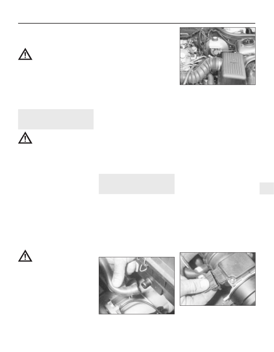
8 Undo the retaining nut at the front, then
loosen off the air duct-to-filter housing clip
screw, and detach the air duct from the
housing (see illustration).
9 Unscrew and remove the two retaining nuts
on the underside of the housing (that secure it
to the location studs).
10 Disconnect the hose at the base of the
unit (to the inlet manifold) and lift the air
cleaner clear.
11 Refit in the reverse order of removal.
Ensure that the air hose and duct are securely
located.
SEFi system
12 Disconnect the battery negative (earth)
lead (refer to Chapter 5, Section 1).
13 Detach the crankcase breather hose from
the air cleaner housing (see illustration).
14 Disconnect the air mass meter wiring
multi-plug, then release the two clips and
withdraw the air mass meter, complete with
inlet hose, from the air cleaner cover (see
illustration). Carefully position the air mass
meter and hose assembly to one side.
Fuel and exhaust systems – fuel-injected engines 4B•3
4.13 Detach the crankcase breather hose
from the air cleaner housing
4.8 General view of the air filter (A) and air
duct (B) fitted to the 1.6 litre EFi engine
4B
4.14 Disconnect the air mass meter wiring
multi-plug, then release the two clips and
withdraw the air mass meter, complete
with inlet hose