Westfalia. Testing repair electrical manual - part 8
 

  Index      Westfalia     Westfalia (903.662) testing repair electrical manual in english


Search            copyright infringement  


Content   ..  6  7  8  9   ..


Westfalia. Testing repair electrical manual - part 8


6

Detach electrical coupling (4)
from the central electronics (2)

 Installation: When installing

new central electronics (2) the
switches (5) on the back should
be adjusted as per the old part.


7

Install in the reverse order


8

Program the central electronics
(2)

 Check customer-specific

adjustments on the central
electronics (2) and adjust if
necessary.


9

Carry out self-test for central
electronics (2)


AR54.21-D-
0021A


110 589 03 59 00


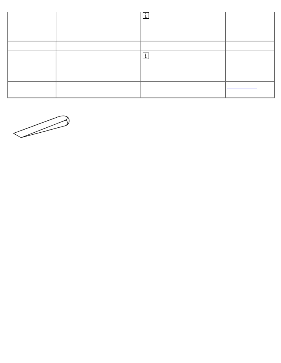
Mounting wedge


AR54.21-D-0021A

Carry out self-test for central electronics

7.5.04

MODEL  903.662


with CODE (ZU8) National version for USA


with CODE (Z29) "James Cook" touring camper, NAFTA

1 Switches 
2 Switches 
3 Switches 
4 Switches 
5 Central electronics


D54.21-1124-10

5 Central electronics 
6 Fresh water level display 
7 Symbol for battery mode 
8 Multiple display 
9 Symbol for mains voltage,
charger
 
10 Symbol for stationary heater
mode
 
11 Symbol for wastewater level
indicator
 
12 Symbol for timer 
13 Symbol for cut-in times for
stationary heater
 
14 Capacity display for additional
batteries
 
15 Symbol for refrigerator box,
refrigerator
 
16 Outside temperature button 
17 Timer button 
18 ON-OFF button 
19 Up button 
20 Battery voltage button 
21 Heater button 
22 Refrigerator box button,
refrigerator button
 
23 Down button


D54.21-1125-04


Procedure


1

Start the self-test by

 The auxiliary heater must be


simultaneously pressing the
outside temperature button (16),
ON-OFF button (18), battery
voltage button (20) and DOWN
button (23)

switched off and the after-run
finished.


 Keep the outside temperature

button (16), ON-OFF button (18),
battery voltage button (20) and
DOWN button (23) for approx. 7
seconds, then start with the self-
tests within 60 seconds.


 The self-test mode is started

when all the symbols appear on
the display of the central
electronics (5).


2

Carry out self-test for switch
position 1 or 2 batteries

 Switch (1) on the back of the

central electronics (5).

AR54.21-D-0021-
01A

3

Carry out self-test for switch
position battery model 1 or 2

 Switch (2) on the back of the

central electronics (5).

AR54.21-D-0021-
02A

4

Carry out self-test for switch
position of refrigerator box or
refrigerator

 Switch (3) on the back of the

central electronics (5).

AR54.21-D-0021-
03A

5

Carry out self-test for switch
position degrees Celsius or
degrees Fahrenheit

 Switch (4) on the back of the

central electronics (5).

AR54.21-D-0021-
04A

6

Carry out self-test for fresh water
sensor


AR54.21-D-0021-
05A

7

Carry out self-test for wastewater
sensor


AR54.21-D-0021-
06A

8

Carry out self-test for refrigerator
temperature and refrigerator box
temperature


AR54.21-D-0021-
07A

9

Carry out self-test for heater
temperature


AR54.21-D-0021-
08A

10

Carry out self-test for battery
current


AR54.21-D-0021-
09A

11

Carry out self-test for refrigerator
and refrigerator box


AR54.21-D-0021-
10A

12

Carry out self-test for heater


AR54.21-D-0021-
11A

13

Carry out self-test for outside
temperature button (16)


AR54.21-D-0021-
12A

14

Carry out self-test for battery
voltage button (20)


AR54.21-D-0021-
13A

15

Carry out self-test for timer
button (17)


AR54.21-D-0021-
14A

16

Carry out self-test for heater
button (21)


AR54.21-D-0021-
15A

17

Carry out self-test for ON-OFF
button (18)


AR54.21-D-0021-
16A

18

Carry out self-test for refrigerator
box button and refrigerator
button (22)


AR54.21-D-0021-
17A

19

Carry out self-test for UP button
(19)


AR54.21-D-0021-
18A

20

Finish self-test by pressing the
DOWN button (23)

 The operating mode stored

before the start of test is
resumed.


AR54.21-D-0030A

Remove/install switched-mode power supply for roof air
conditioning

22.4.04

MODEL  903.662


with CODE (ZU8) National version for USA


with CODE (Z29) "James Cook" touring camper, NAFTA

1 Cover 
2 Bleeding


D54.21-1110-06

D54.21-1114-09

3 Switched-mode power supply 
4 Electrical connector 
6 Load relay


7 Electrical wiring 
8 Electrical line


9 Electrical line 
10 Electrical line

3 Switched-mode power supply 
5 Hose clamps 
11 Bolts 
12 Nut


D54.21-1118-06

D54.21-1121-08

3 Switched-mode power supply 
13 Electrical line


14 Electrical connector 
15 Line bridges


16 Bolts 
17 Carrier plate


Remove/Install


 Danger!

Risk of death from coming into
contact with electrical parts of
the 110 V system Risk of injury
caused by burns, which can be
produced by electrical shocks or
by body parts coming in direct
contact with electrical currents.

Do not touch any conductive
parts of the 110 V system.

AS00.00-Z-0027-
01A

Evaluating electronic
components after repair and
painting work and after accidents

All models

AH54.00-P-1000-
01A

1

Switch off roof air conditioning

 See Operator's Manual


2

Separate external 110-V feed
line from the vehicle

 See Operator's Manual


3

Remove web-type fuse

of the roof air conditioning in the
engine compartment

AR54.15-D-
2100B

4

Remove cover (1)


AR54.21-D-0030-
01A

5

Remove venting of switched-
mode power supply (2)


AR54.21-D-
0031A

6

Mark installation position of
electrical lines (7, 8, 9, 10, 13)

 Mixing up the electrical lines

(7, 8, 9, 10, 13) can result in
short circuit and therefore result
in the destruction of electrical
components.


7

Disconnect electrical connector
(4)


8

Unscrew nut of electrical line (9)
at the top from the load relay (6)


9

Remove electrical line (9) from
load relay (6)


10

Unscrew nut of electrical line
(10) from load relay (6)


11

Remove electrical line (10) from
load relay (6)


12

Unscrew nut of electrical line (7)
from switched-mode power
supply (3)


13

Remove electrical line (7) from
switched-mode power supply (3)


14

Unscrew nut of electrical line (8)
from switched-mode power
supply (3)


15

Remove electrical line (8) from
switched-mode power supply (3)


16

Unscrew bolts (11).


17

Unscrew nut (12)

 Installation: Replace self-

locking nut (12).


Notes on self-locking nuts and
bolts

All models

AH00.00-N-0001-
01A

 Danger!

Risk of injury caused by hot
water exiting from the lines of the
fresh water system

Shut off the water heater in a
timely manner before starting
repair work. Let the water in the
lines and in the components of
the fresh water system cool
down to room temperature.

AS86.00-Z-0002-
01A

18

Carrier plate (17) with switched-
mode power supply (3)

 Do not loosen or detach hose

clamps (5).


 If there is a shortage of space

the hose clamps (5) on the hot-
water heater are to be twisted.


19

Unscrew nut of electrical line
(13) from switched-mode power
supply (3)


20

Remove electrical line (13) from
switched-mode power supply (3)


21

Separate electrical connector


Content   ..  6  7  8  9   ..