Westfalia. Testing repair electrical manual - part 6
 

  Index      Westfalia     Westfalia (903.662) testing repair electrical manual in english


Search            copyright infringement  


Content   ..  4  5  6  7   ..


Westfalia. Testing repair electrical manual - part 6


AR54.10-D-1021A

Remove/install 110 V internal socket

28.6.04

MODEL  903.662


with CODE (ZU8) National version for USA


with CODE (Z29) "James Cook" touring camper, NAFTA


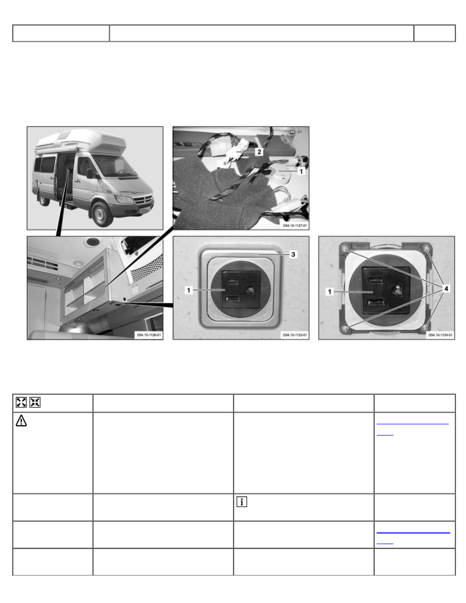
in longitudinal wall cupboard

D54.10-1128-09

1 110 V internal socket 
2 Electrical connector


3 Covering


4 Bolts


Remove/Install


 Danger!

Risk of death from coming into
contact with electrical parts of
the 110 V system Risk of injury
from burns which may be caused
by electric shock or by current
flowing directly through parts of
the body.

Do not touch voltage conducting
parts in the 110 V system.

AS00.00-Z-0027-
01A

1

Disconnect external 110 V feed
line from vehicle

 See Operating Instructions


2

Remove right floor in cupboard

In longitudinal wall cupboard

AR86.60-D-0050-
01A

3

Remove foam pads from lines
around 110 V internal socket (1)


4

Disconnect electrical connector
(2)


5

Release covering (3)

 Mounting wedge

110 589 03 59 00

6

Remove bolts (4).


7

Remove 110 V internal socket
(1)


8

Install in the reverse order


9

Perform a function test

 Connect external 110 V feed

line to vehicle and electrical
consumers to 110 V internal
socket (1) and check that they
function correctly.


110 589 03 59 00


Mounting wedge


AR54.10-D-1021B

Remove/install 110 V internal socket

28.6.04

MODEL  903.662


with CODE (ZU8) National version for USA


with CODE (Z29) "James Cook" touring camper, NAFTA


on transverse wall cupboard

1 110 V internal socket 
2 Electrical connector 
3 Covering 
4 Bolts


D54.10-1125-06


Remove/Install


 Danger!

Risk of death from coming into
contact with electrical parts of
the 110 V system Risk of injury
from burns which may be caused
by electric shock or by current
flowing directly through parts of
the body.

Do not touch voltage conducting
parts in the 110 V system.

AS00.00-Z-0027-
01A

1

Disconnect external 110 V feed
line from vehicle

 See Operating Instructions


2

Remove wall cupboard cover
panel

On right at side

AR86.60-D-0051-
01A

3

Remove wall cupboard cover
panel

On right at rear

AR86.60-D-0051-
01B

4

Disconnect electrical connector
(2)


5

Remove cable ties from lines
around 110 V internal socket (1)


6

Release covering (3)

 Mounting wedge

110 589 03 59 00

7

Remove bolts (4).


8

Remove 110 V internal socket
(1)


9

Install in the reverse order


10

Perform a function test

 Connect external 110 V feed

line to vehicle and electrical
consumers to 110 V internal
socket (1) and check that they
function correctly.


110 589 03 59 00


Mounting wedge


AR54.10-D-1040A

Remove/install battery charger

27.5.04

MODEL  903.662


with CODE (ZU8) National version for USA


with CODE (Z29) "James Cook" touring camper, NAFTA


110-V system for additional batteries

D54.10-1116-09

1 Bench seat 
2 Electrical connector 
3 Electrical connector


4 Electrical connector 
5 Screw 
6 Ground line


7 Bolts 
8 Battery charger


Remove/Install


1

Separate external 110-V feed
line from vehicle

 See Operating Instructions


2

Position bench seat (1) forward

 See Operating Instructions


3

Remove panel at front of kitchen
block

Paneling in front of battery
charger.

AR68.30-D-4630-
01A

4

Detach electrical couplings (2, 3,
4) from battery charger (8)


5

Loosen screw (5)


6

Remove ground line (6) from
battery charger (8)


7

Unscrew bolts (7).


8

Remove battery charger (8)


9

Install in the reverse order


10

Perform function check

 With an external 110-V

connection the symbol for the
mains voltage of the charger
must appear on the display of the
central electronics (see
operator's manual).


AR54.15-D-0061A

Remove/install 110 V circuit breaker

27.5.04

MODEL  903.662


with CODE (ZU8) National version for USA


with CODE (Z29) "James Cook" touring camper, NAFTA

D54.15-1121-08

1 Bolts 
2 Cover


3 Bolts 
4 Circuit breaker


5 Bow


Remove/Install


 Danger!

Risk of death from coming into
contact with electrical parts of
the 110 V system Risk of injury
caused by burns, which can be
produced by electrical shocks or
by body parts coming in direct
contact with electrical currents.

Do not touch any conductive
parts of the 110 V system.

AS00.00-Z-0027-
01A

1

Separate external 110-V feed
line from the vehicle

 See Operator's Manual


2

Remove bolts (1)


3

Take off cover (2)


4

Loosen screws (3) of circuit
breaker (4) to be removed


5

Pull leads out of the circuit
breaker (4) to be removed


6

Unlock the circuit breaker (4) at
the bottom of the bracket (5)


7

Take out the circuit breaker (4)
forwards


8

Install in the reverse order


9

Perform function check

 With an external 110-V

connection, the symbol for
charger mains voltage must
appear on the central electronics
display (see operator's manual).


Content   ..  4  5  6  7   ..