Snowmobile Lynx UTILITY ACE SERIES. OPERATOR’S GUIDE (2024) - page 3

EQUIPMENT
When riding, both hands should remain on the handlebar grips to pro-
vide braking capability, as well proper steering and directional control.
Do not use handlebar strap for towing, lifting or side hilling.
WARNING
Do not use while riding at speed. Steering control is highly re-
duced and brake control is not possible.
Electriic Visor Jack Connector
An electric visor can be connected to the jack connector. A stress re-
lief extension is supplied with the vehicle.
TYPICAL — DRIVER - ELECTRIC VISOR JACK CONNECTOR
LOCATION
Drive Belt Guard
Removing the Drive Belt Guard
WARNING
NEVER operate engine:
– Without shields and belt guard securely installed.
– With hood and/or side panels opened or removed.
NEVER attempt to make adjustments to moving parts while en-
gine is running.
144
EQUIPMENT
NOTE:
Belt guard is purposely made slightly oversize to maintain tension on
its pins and retainers preventing undue noise and vibration. It is impor-
tant that this tension be maintained when reinstalling.
Remove tether cord cap from engine cut-off switch.
Open the LH side panel. See procedure in this section.
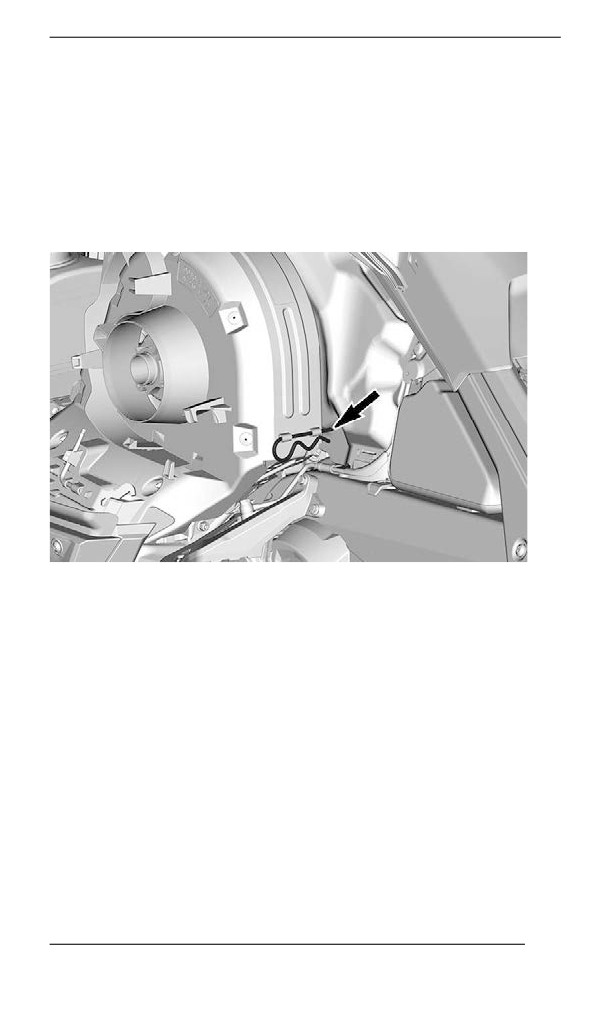
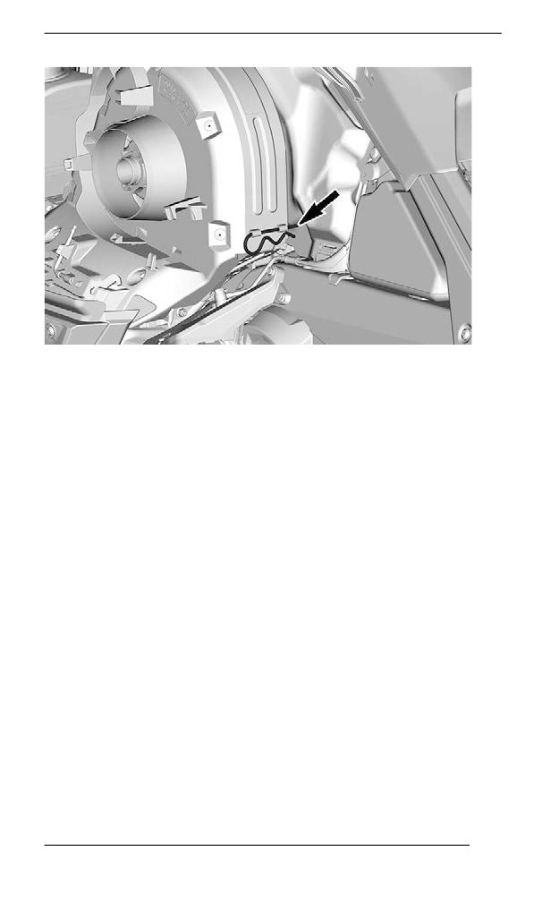
Remove retaining pin.
TYPICAL
Lift rear portion of guard then release from front tab.
Installing the Drive Belt Guard
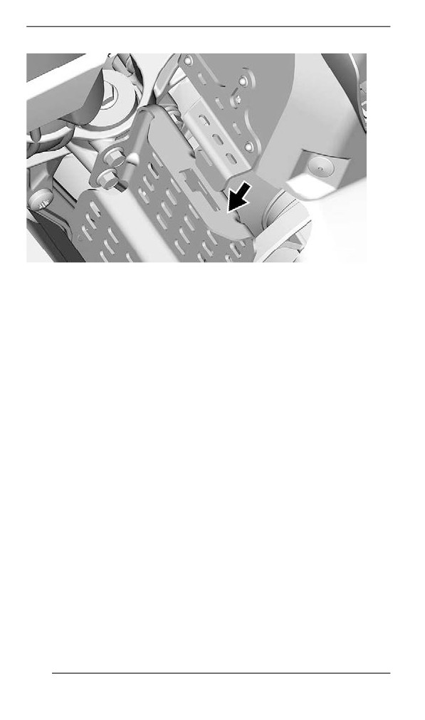
1. Insert belt guard tab in front support slot.
145
EQUIPMENT
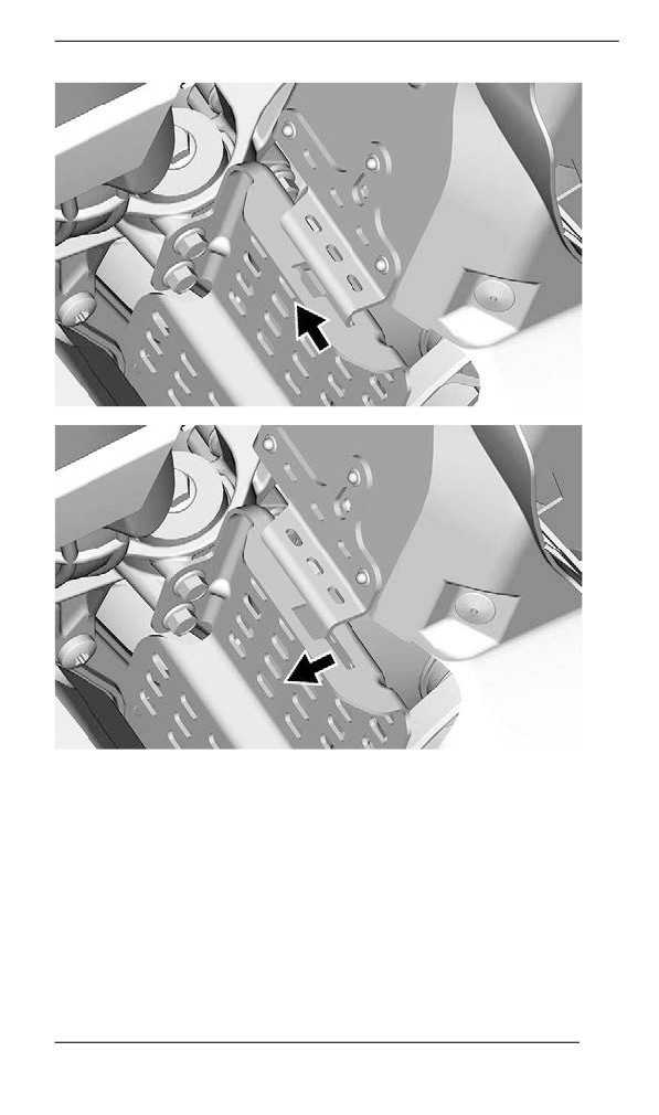
2. Push drive belt guard toward engine then toward front of vehicle.
146
EQUIPMENT
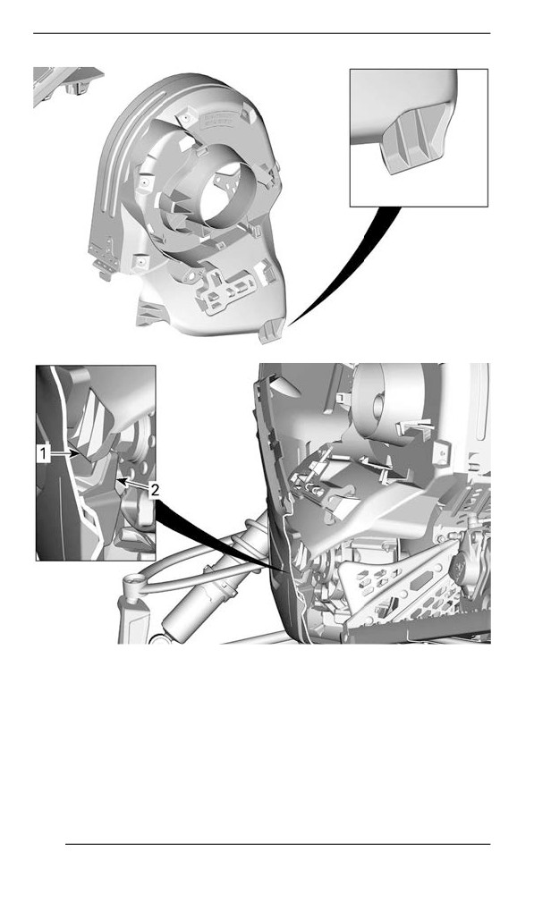
3. Insert belt guard tab between bottom pan and hook.
147
EQUIPMENT
LH SIDE BOTTOM PAN - CROSSCUT VIEW
1. Belt guard tab
2. Bottom pan hook
4. Position the rear portion of the belt guard over the retainer and se-
cure it using the retaining pin.
148
EQUIPMENT
Spare Driive Bellt Hollder
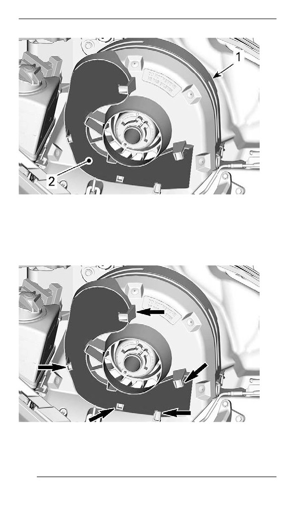
A spare drive belt can be stored in a holder located on the drive belt
guard.
NOTE:
The spare drive belt is not supplied with the snowmobile.
Position spare drive belt into drive belt guard slot.
149
EQUIPMENT
TYPICAL
1. Drive belt guard
2. Slot
Secure in place by sliding it behind the tabs.
TYPICAL
150
EQUIPMENT
Tools
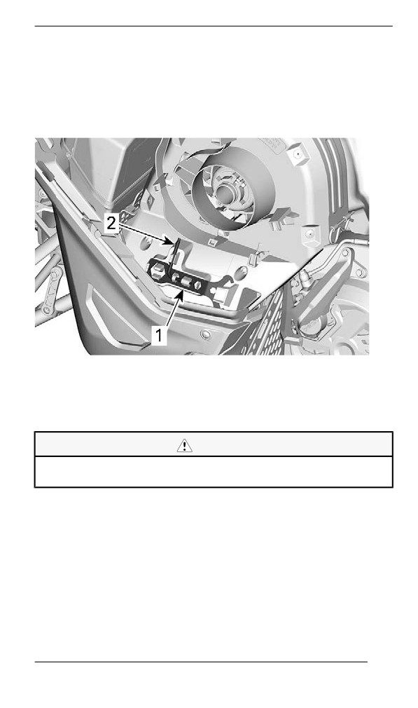
A part of the drive belt guard is designed to hold the tools allowing for
basic maintenance.
The tools are supplied with the vehicle. They should always be in-
stalled in their proper location and orientation.
TYPICAL - DRIVE BELT GUARD TOOLS LOCATION
1. Suspension adjustment tool
2. Pulley expander and headlight adjustment tool
Install in the following sequence:
CAUTION
Make sure tools are secured properly. Tools may detach and
cause damage to rotating parts.
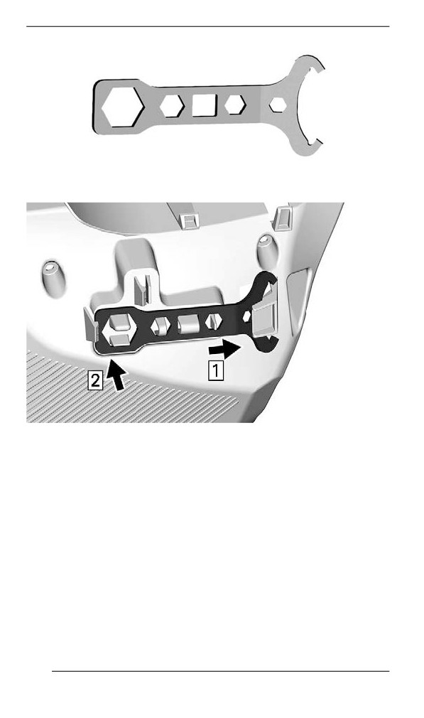
1. Slide the suspension adjustment tool open end under retaining tab.
151
EQUIPMENT
SUSPENSION ADJUSTMENT TOOL
2. Press the closed end on the retaining tabs.
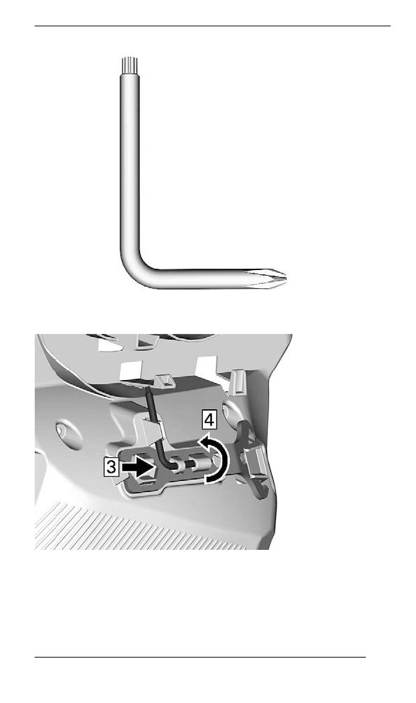
3. Slide the Pulley expander and headlight adjustment tool short end
into hole.
152
EQUIPMENT
PULLEY EXPANDER AND HEADLIGHT ADJUSTMENT TOOL
4. Rotate and clip long end in place.
Rear Storage Compartment (if equipped)
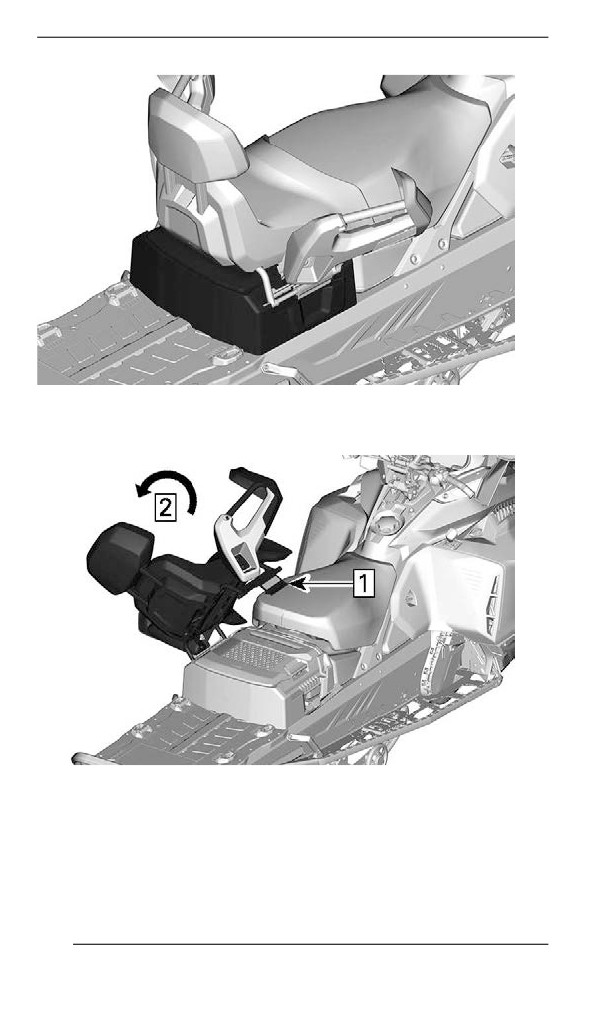
A storage compartment is located at the rear of the seat, above the
battery cover.
153
EQUIPMENT
TYPICAL
To open, tilt passenger seat.
TYPICAL
1. Unlock seat latch
2. Tilt passenger seat
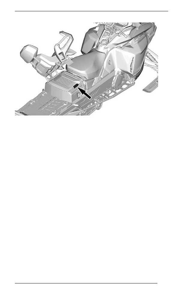
Lift handle.
154
EQUIPMENT
TYPICAL
155
EQUIPMENT
Cargo Box (iif equipped)
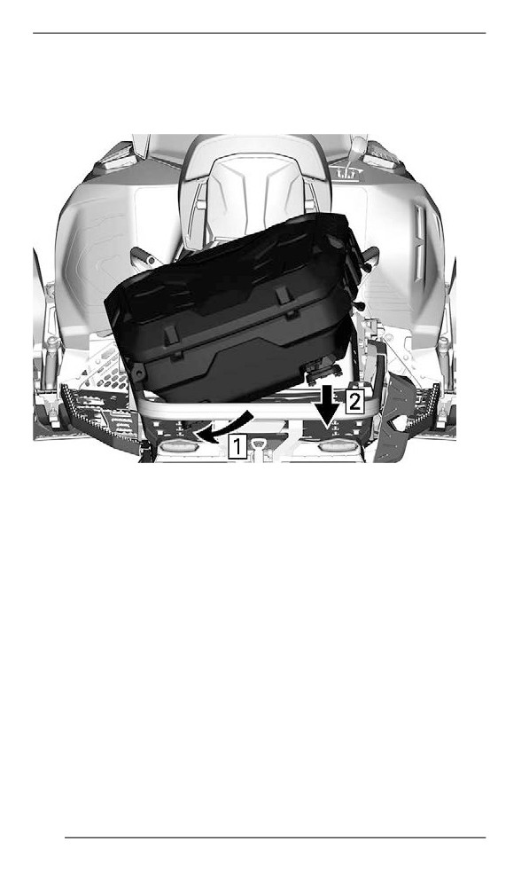
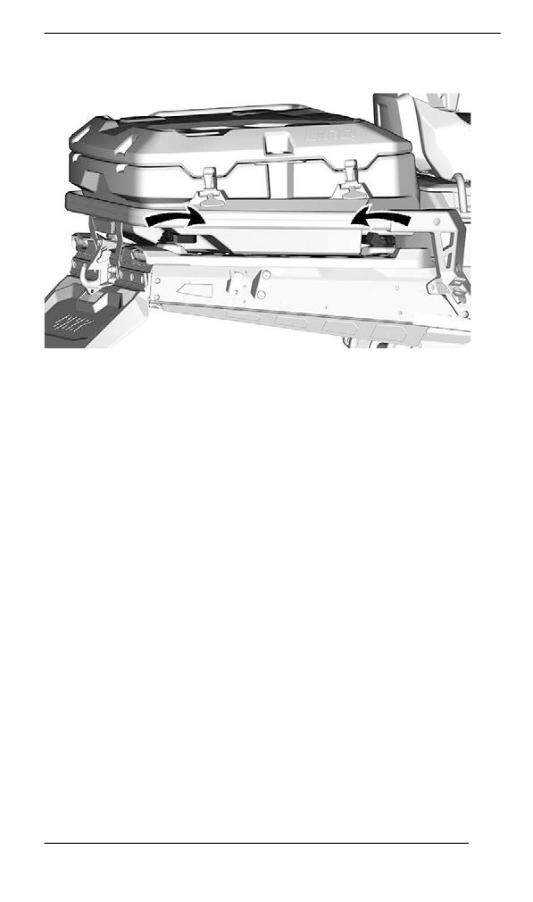
The cargo box is secured by LinQ attachment. To Install, follow the
steps.
1. Slide cargo bag toward LH side.
2. Lower cargo bag.
156
EQUIPMENT
Turn LinQ levers as shown to lock.
157
EQUIPMENT
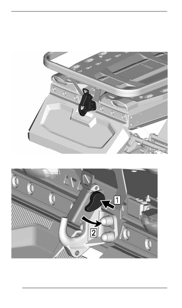
Hitch
NOTE:
Refer to decal on vehicle for towing weight capacities.
To open the hook, push and turn the handle to retract locking plate.
When attaching any accessory, always refer to the manufacturer's
recommendations.
158
EQUIPMENT
WARNING
Never tow an accessory with a rope. Always use a rigid tow bar.
Using a rope would result in a collision between the object and
the snowmobile and possibly in a tip over in case of a rapid de-
celeration or on a downward slope.
159

GAUGE – 4.5” DIGITAL DISPLAY
Mulltiifunction Diispllay
Lower Display
May display the following:
- RPM
- Speed
- Engine Temperature
- Fuel Statistics
- Settings
- Messages
- Outside temperature (if equipped)
To change the displayed information, use the gauge LOWER (M) but-
ton, or the Mode button on the handlebar multifunction switch, if
equipped.
The SPEED STAT display shows the maximum and the averaged
speed. Hold LOWER button for 3 seconds to reset.
When the SPEED display is chosen, the RPM is shown in the TRIP
display.
160
GAUGE - 4.5” DIGITAL DISPLAY
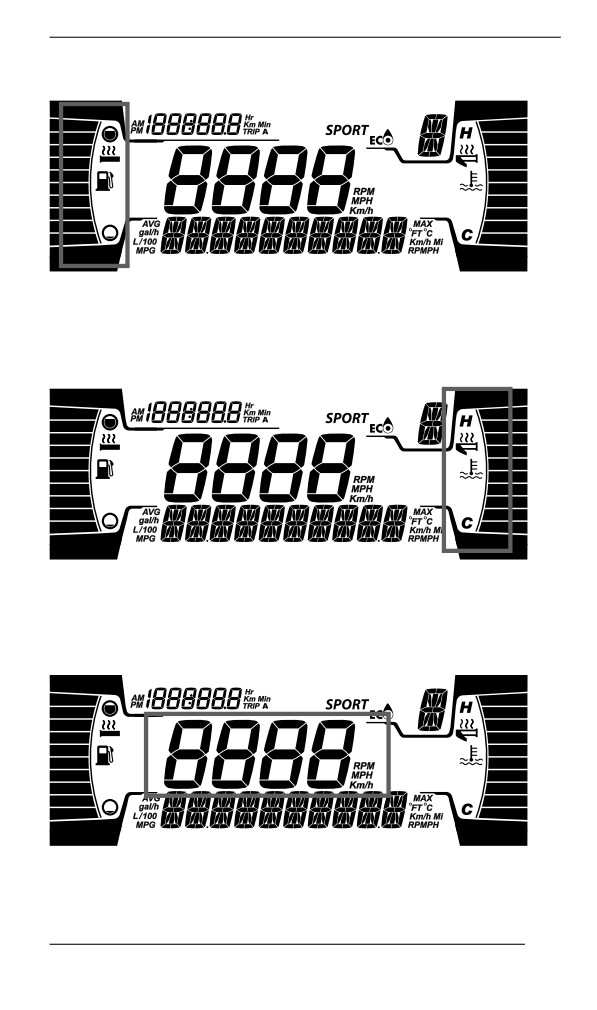
Left Lateral Display
The left lateral display includes:
- Fuel level indicator
- Heated Grip level
Right Lateral Display
The right lateral display includes:
- Engine Temperature
- Heated throttle indicator
Central Display
Display the RPM of the engine or the vehicle speed in Km/h or MPH.
161
GAUGE - 4.5” DIGITAL DISPLAY
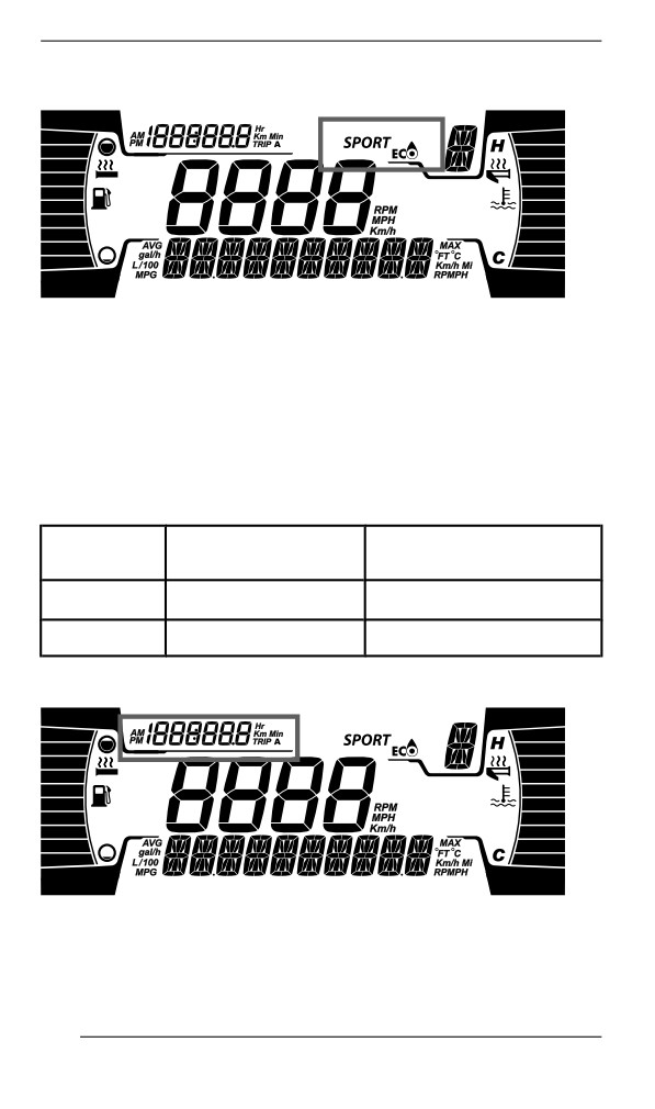
Driving Mode Display
The MODE display indicates the selected mode of operation:
- SPORT
- ECO
- STANDARD
NOTE:
When in STANDARD mode, no information is displayed.
A message of the selected mode will be displayed on the lower display
at activation and deactivation as follow:
DRIVING
MESSAGE AT
MESSAGE AT
MODE
ACTIVATION
DEACTIVATION
Sport
Sport
Sport OFF
Eco
Eco
Eco OFF
Trip Display
This display shows trip informations:
- Cumulative distance odometer
- Trip A hours
162
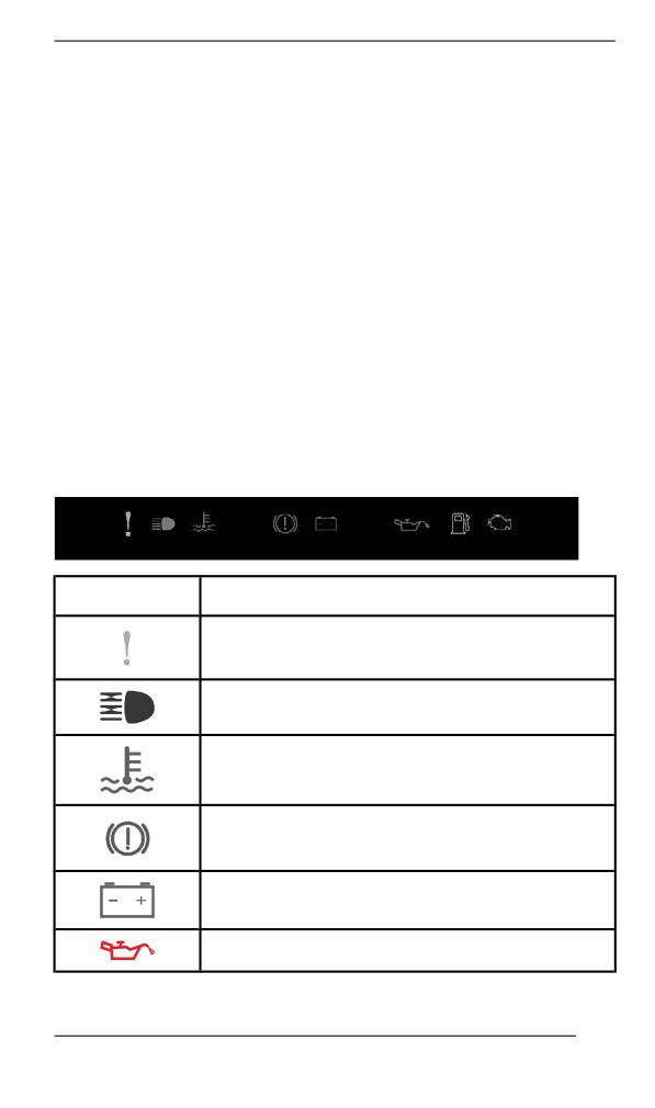
GAUGE - 4.5” DIGITAL DISPLAY
- Trip A distance (Km or mph)
- Vehicle hour meter
- Clock (If battery equipped)
To change the displayed information, use the gauge UPPER (T) but-
ton, or the Trip button on the handlebar multifunction switch, if
equipped.
Warniing Lamps and Indiicators
The following indicator lamps will alert you to a vehicle condition that
may become serious. Some lamps will illuminate when starting the ve-
hicle to make sure they work. If any lamps remain on after starting the
vehicle, refer to the respective system warning lamp for further
information.
NOTE:
Some warning indicators appear in the display of the multifunction
gauge and function the same as an indicator lamp but do not display
when starting the vehicle.
Telltale Lights - Lower Bar
Lights
Description
ORANGE - Vehicle malfunction
BLUE - The high beam are selected
RED - The engine temperature is too high.
RED - Parking brake is engaged or malfunction
of the brake system
RED - The battery voltage too low or problem
with the electrical system
RED - Low engine oil pressure (if applicable)
163
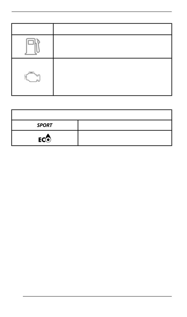
GAUGE - 4.5” DIGITAL DISPLAY
Lights
Description
ORANGE - Low fuel level
ORANGE
Turn on: Malfunction of the vehicle emissions
control system
Blink: Engine problems, the limp home mode is
activated. Have the vehicle serviced
immediately.
Icons and Indicators - Multifunction Display
Icons and Indicators
Denotes SPORT mode is selected.
Denotes ECO mode is selected.
164
GAUGE - 4.5” DIGITAL DISPLAY
Settiings
Setup
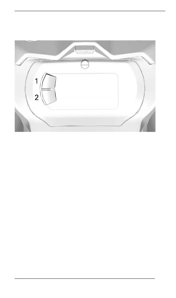
1. Upper button (Trip)
2. Lower button (Menu)
NOTE: A Trip and a Menu buttons can be found on the handlebar
multifunction switch, if equipped.
Using the LOWER (M) button, select SETTINGS and hold to enter
setting menu.
Reset Stats
Using LOWER button, select RESET STAT and hold to reset.
Unit Selection
This multifunction gauge is factory preset in metric units but it is possi-
ble to change it to imperial units.
Using LOWER button, select UNITS and hold button to change units.
Setting Clock
Using LOWER button, select CLOCK to change the clock.
1. Press LOWER button to select clock display.
2. Push and hold LOWER button for 1 second.
165
GAUGE - 4.5” DIGITAL DISPLAY
3. Press LOWER button to select 12:00 AM PM or 24:00 time base.
4. Push and hold LOWER button to acknowledge selection.
5. Press LOWER button to change hours (hours flash).
6. Push and hold LOWER button to acknowledge hour selection.
7. Press LOWER button to switch to minutes (minutes flash).
8. Push and hold LOWER button to acknowledge minutes selection.
Setting Language
The gauge display language can be changed. Refer to an authorized
BRP snowmobile dealer for language availability and to setup the
gauge to your preference.
166
GAUGE – 7.2” DIGITAL DISPLAY
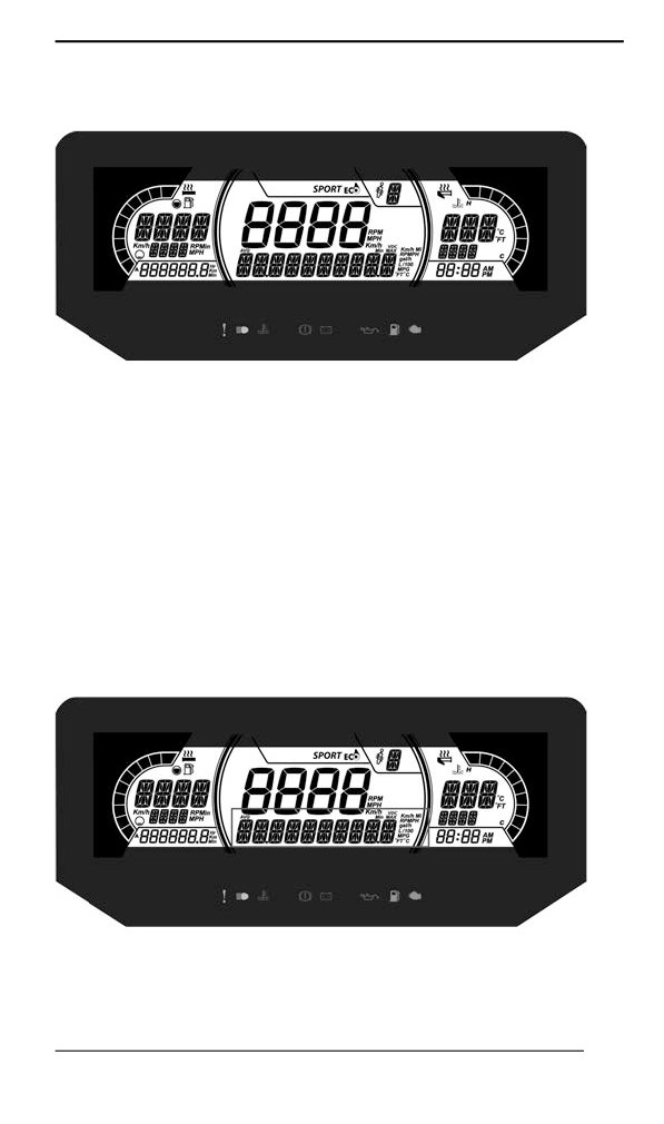
Multifunctiion Display
1. Select the upper or center display by using the MENU (M) button
on the multifunction switch. Refer to Secondary Controls for Menu/
Set button location.
2. While the desired display is flashing, navigate through the display,
by using the SET (S) button on the multifunction switch.
Once the desired information is displayed, press the MENU (M)
button or wait 5 seconds to confirm.
To reset
- Average speed
- Top speed
- Total fuel consumption
Press and hold the SET (S) button while display is flashing.
Lower Display
7.2" DIGITAL LOWER DISPLAY
May display the following:
- Settings
167
GAUGE - 7.2” DIGITAL DISPLAY
- Messages
The SPEED display shows the Maximum and the averaged speed.
Hold MENU button for 3 seconds to reset.
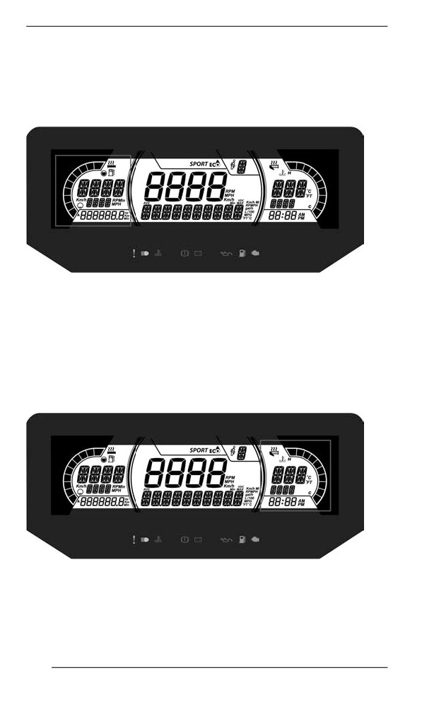
Left Lateral Display
The left lateral display includes:
- Fuel level indicator
- Heated Grip level
- Trip distance A and B (Km or mph)
- Cumulative hours
- Speed
- RPM
- Odometer
Right Lateral Display
The right lateral display includes:
- Engine Temperature
- Heated throttle indicator
- Clock
168
GAUGE - 7.2” DIGITAL DISPLAY
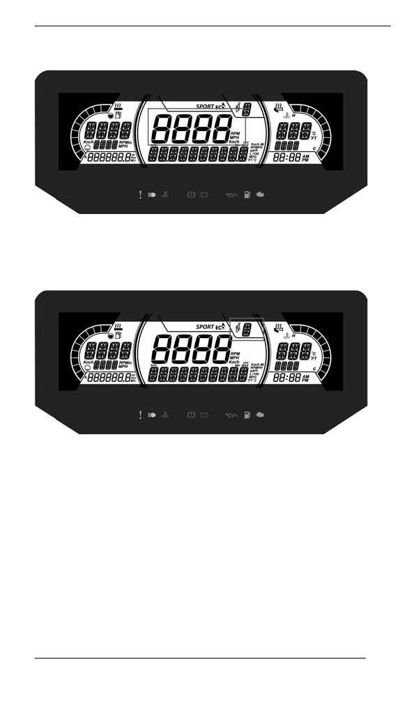
Central Display
Display the vehicle speed in Km/h (or MPH) or the RPMs. Refer to
Settings.
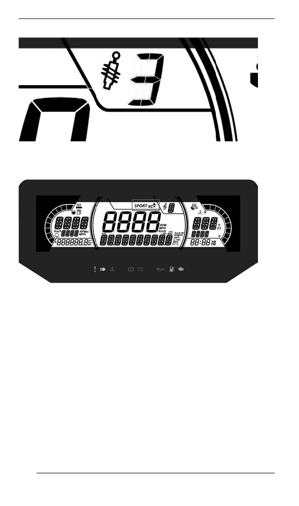
ACS Suspension Position Display (if equipped)
This display shows suspension setting.
The suspension is calibrated from 1 to 5, 1 being the softest setting.
169
GAUGE - 7.2” DIGITAL DISPLAY
Refer to TUNE YOUR RIDE section for proper adjustment procedure.
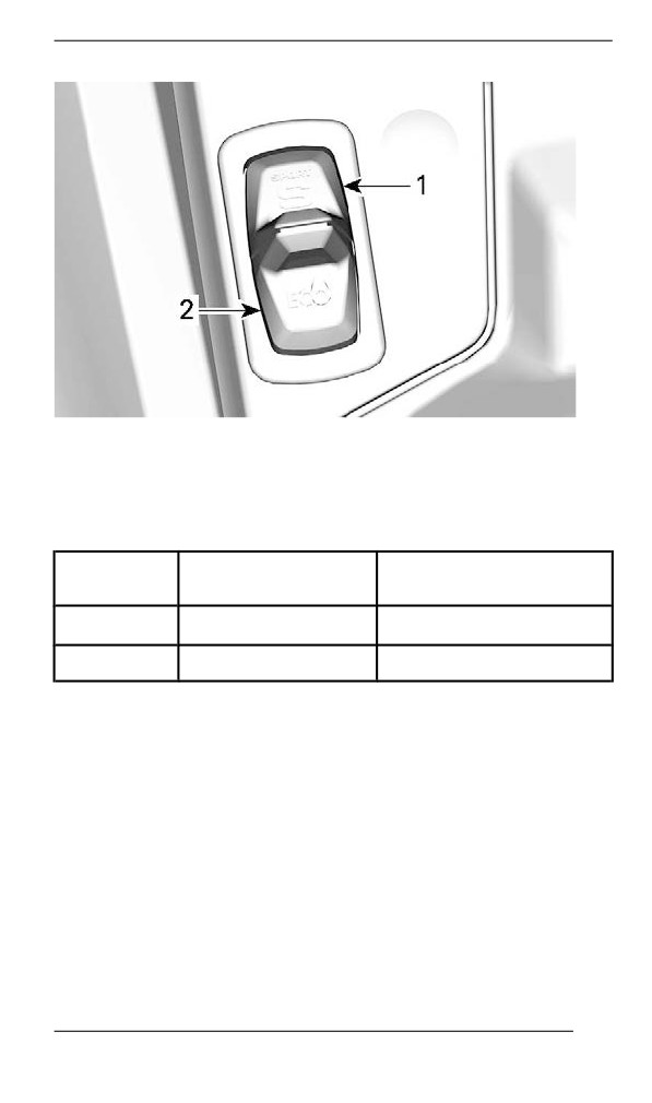
Driving Mode Display
The driving mode display indicates the selected mode of operation:
- SPORT
- ECO
- STANDARD
170
GAUGE - 7.2” DIGITAL DISPLAY
NOTE:
When in STANDARD mode, no information is displayed.
A message of the selected mode will be displayed on the lower display
at activation and deactivation as follow:
DRIVING
MESSAGE AT
MESSAGE AT
MODE
ACTIVATION
DEACTIVATION
Sport
Sport
Sport OFF
Eco
Eco
Eco OFF
Warniing Lamps and Indiicators
The following indicator lamps will alert you to a vehicle condition that
may become serious. Some lamps will illuminate when starting the ve-
hicle to make sure they work. If any lamps remain on after starting the
vehicle, refer to the respective system warning lamp for further
information.
NOTE:
Some warning indicators appear in the display of the multifunction
gauge and function the same as an indicator lamp but do not display
when starting the vehicle.
171
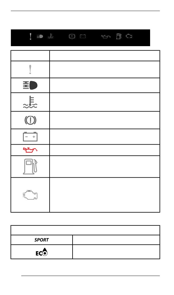
GAUGE - 7.2” DIGITAL DISPLAY
Telltale Lights - Lower Bar
Lights
Description
ORANGE - Vehicle malfunction
BLUE - The high beam are selected
RED - The engine temperature is too high.
RED - Parking brake is engaged or malfunction
of the brake system
RED - The battery voltage too low or problem
with the electrical system
RED - Low engine oil pressure (if applicable)
ORANGE - Low fuel level
ORANGE
Turn on: Malfunction of the vehicle emissions
control system
Blink: Engine problems, the limp home mode is
activated. Have the vehicle serviced
immediately.
Icons and Indicators - Multifunction Display
Icons and Indicators
Denotes SPORT mode is selected.
Denotes ECO mode is selected.
172
GAUGE - 7.2” DIGITAL DISPLAY
Settiings
Setup
Using MENU button, select SETTINGS and hold to enter setting
menu. Various options are available such as swapping the SPEED
and RPM in the Central Display.
Unit Selection
This multifunction gauge is factory preset in metric units but it is possi-
ble to change it to imperial units.
Using MENU button, select UNITS and hold button to change units.
Setting Clock
Using MENU button, select CLOCK and hold to change units.
1. Press MENU button to select clock display.
2. Push and hold MENU button for 1 second.
3. Press MENU button to select 12:00 AM PM or 24:00 time base.
4. Push and hold MENU button or OK button to acknowledge
selection.
5. Press MENU button to change hours (hours flash).
6. Push and hold MENU button or OK button to acknowledge hour
selection
7. Push MENU button to switch to minutes (minutes flash).
8. Press MENU button to change minutes.
Setting Language
The gauge display language can be changed. Refer to an authorized
BRP snowmobile dealer for language availability and to setup the
gauge to your preference.
173
FUEL
Fuel Requirements
NOTICE
Always use fresh gasoline. Gasoline will oxidize; the result is
loss of octane, volatile compounds, and the production of gum
and varnish deposits which can damage the fuel system.
Alcohol fuel blending varies by country and region. Your vehicle has
been designed to operate using the recommended fuels, however, be
aware of the following:
- Use of fuel containing alcohol above the percentage specified by
government regulations is not recommended and can result in the
following problems in the fuel system components:
- Starting and operating difficulties.
- Deterioration of rubber or plastic parts.
- Corrosion of metal parts.
- Damage to internal engine parts.
- Inspect frequently for the presence of fuel leaks or other fuel sys-
tem abnormalities if you suspect the presence of alcohol in gaso-
line exceeds the current government regulations.
- Alcohol blended fuels attract and hold moisture which may lead to
fuel phase separation and can result in engine performance prob-
lems or engine damage.
Recommended Fuel
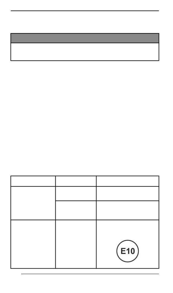
Use unleaded gasoline containing MAXIMUM 10% ethanol. The gaso-
line must have the following minimum octane requirements:
Fuel type
Engine
Minimum octane rating
600 ACE
87 AKI (RON+MON)/2
900 ACE
92 RON
Fuel with NO
ethanol
900 ACE Turbo
91 AKI (RON+MON)/2
900 ACE Turbo
95 RON
R
91 AKI (RON+MON)/2
95 RON
600 ACE
Fuel which may
900 ACE
contain up to 10%
900 ACE Turbo
MAX ethanol
900 ACE Turbo
R
174
FUEL
NOTICE
Never experiment with other fuels. Engine or fuel system dam-
ages may occur with the use of an inadequate fuel.
NOTICE
Do NOT use fuel from fuel pumps labeled E85.
Use of fuel labeled E15 is prohibited by U.S. EPA Regulations.
Fueliing Procedure
WARNING
Always stop engine before refueling.
WARNING
Fuel is flammable and explosive under certain conditions.
Never use an open flame to check fuel level.
Never smoke or allow flame or spark in vicinity.
Always work in a well-ventilated area.
NOTE:
Do not sit or lean on seat when fuel tank cap is not properly installed.
1. Stop engine.
2. Have operator and passenger get off vehicle.
WARNING
Do not allow anyone seated on the vehicle while fueling.
3. Unscrew slowly the fuel reservoir cap counterclockwise to stabilize
pressure before removing it.
NOTE:
A short whistling sound is normal.
175
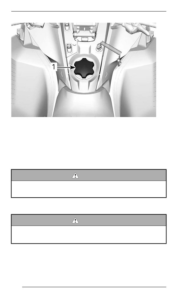
FUEL
TYPICAL
1. Fuel tank cap
4. Insert the spout into the filler neck.
5. Pour fuel slowly so that air can escape from the tank and prevent
fuel flow back. Be careful not to spill fuel.
6. Stop filling when the fuel reaches the bottom of filler neck. Do not
overfill.
WARNING
Never top up the fuel tank before placing the vehicle in a warm
area. As temperature increases, fuel expands and may
overflow.
7. Fully tighten fuel reservoir cap clockwise.
WARNING
Always wipe off any small fuel spillage from the vehicle. If a ma-
jor spillage occurs, remove side panels to remove fuel vapors
from engine compartment before starting.
NOTE:
Do not sit or lean on seat when fuel tank cap is not properly installed.
176
ENGINE OIL
Recommended Oill
Rotax® engines were developed and validated using the XPS™ oil.
BRP recommends the use of its XPS engine oil or an equivalent at all
time. Do not add any oil additives to the recommended engine oil.
Damages caused by the use of an oil not suitable for the engine or by
adding of an oil additives may not be covered by the BRP Limited
Warranty.
XPS RECOMMENDED Engine Oil
4T 0W40 Synthetic oil
IF THE RECOMMENDED XPS ENGINE OIL IS NOT
AVAILABLE
Use a 0W40 4-stroke SAE synthetic engine oil meeting or
exceeding the following lubricant industry specifications.
Always check the API service label certification on the oil container,
it must contain at least the indicated standard.
- API service classification SN
177
BREAK-IN PERIOD
Operatiion During Break-In
Engine
During the break-in period:
- Avoid prolonged full throttle operation.
- Avoid sustained accelerations.
- Avoid prolonged cruising speeds.
- Avoid engine overheating.
However, brief accelerations and speed variations contribute to a
good break-in.
During a predetermined period, the engine management system con-
trols some engine parameters.
The duration is based on fuel volume. It will take approximately two
fuel tanks to complete the break-in.
During this period:
- The engine performance and behavior will not be optimal.
- The fuel and oil consumption will be higher.
Drive Belt
A new drive belt requires a break in period of 50 km (30 mi).
During the break-in period:
- Avoid strong acceleration and deceleration.
- Avoid pulling a load.
- Avoid high speed cruising.
If the vehicle creeps, lower the drive belt height from the preliminary
setting. Refer to Drive Belt in maintenance procedure.
178
BASIC PROCEDURES
Engine Startiing Procedure
Procedure
1. Apply parking brake.
2. Recheck throttle control lever operation.
3. Put your helmet on.
4. Ensure that the tether cord cap is installed on the engine cut-off
switch and that the cord is attached to your clothing eyelet.
5. Ensure that the emergency engine stop switch is in the ON position
(up).
WARNING
Never depress throttle while starting engine.
6. Release parking brake.
NOTE:
For an initial cold start, do not release parking brake. Perform the ve-
hicle warm-up procedure as explained below.
7. Depress the START button to engage the electric starter and start
the engine. Release button immediately when engine has started.
NOTICE
Do not engage electric starter for more than 10 seconds at a
time. A rest period should be observed between the cranking
cycles to allow electric starter to cool down.
Emergency Startiing
Do not attempt any emergency starting procedure. Have the battery
charged or replaced.
Vehicle Warm-Up
Before every ride, vehicle has to be warmed up as follows.
1. Start engine as explained in ENGINE STARTING PROCEDURE
(PAGE 179) ENGINE STARTING PROCEDURE above.
2. Allow engine to warm up one or two minutes at idle speed.
NOTE:
Engine will shut down after approximately 12 minutes of idling.
179
BASIC PROCEDURES
3. Disengage parking brake.
4. Apply throttle until drive pulley engages. Drive at low speed the first
two or three minutes.
NOTICE
If vehicle does not move when throttle is applied, stop engine,
remove tether cord cap from the engine cut-off switch, then do
the following.
– Check if skis are stuck on the ground. Lift one ski at a time
by the handle, then put it down.
– Check if track is stuck on the ground. Lift rear of snowmobile
enough to clear track from the ground, then drop.
– Check rear suspension for hard snow or ice accumulation
that could interfere with track rotation. Clean the area.
– Validate that transmission is engaged (not in neutral).
CAUTION
Beware of injuries by using proper lifting techniques, notably
using your legs force. Do not attempt to lift the rear of vehicle if
it is above your limits.
WARNING
Make sure tether cord cap is removed before standing in front
the vehicle, getting close to the track or rear suspension
components.
NOTE:
Warm-up is electronically controlled. During this period (up to 10 mi-
nutes depending on ambient temperature), engine RPM is limited.
Shiiftiing iin Hiigh or Low range
This transmission is designed to accept shifting while moving. How-
ever, shifting while the engine is under heavy load is not
recommended.
NOTICE
Shifting at a speed faster than 30 km/h (19 MPH) may cause
serious damage to the gearbox.
180
BASIC PROCEDURES
High Range
This position selects the high speed range of the gearbox. It is the nor-
mal driving speed range. It allows the vehicle to reach its maximum
speed.
Low Range
This position selects the low speed range of the gearbox. It allows the
vehicle to move slowly with maximum engine torque.
Low range should be used whenever:
- Pulling a cargo carrier or accessory
- Hauling a load
- Crossing obstacles
- Climbing onto trailer
- Hill climbing
It is also recommended to use low range if driving for prolonged peri-
ods at speeds under 24 km/h (15 MPH).
NOTICE
Use the low speed range to pull a cargo carrier, carry heavy
cargo, go over obstacles or drive uphill and downhill.
Shifting in Reverse
1. Bring vehicle to a complete stop.
2. Apply and hold brake. Remain seated, refer to Rider Position (Re-
verse Operation) in Riding the vehicle for posture information.
3. With engine at idle speed, select reverse (R) gear using the re-
verse lever or Start / RER button.
Models with Reverse Lever
181
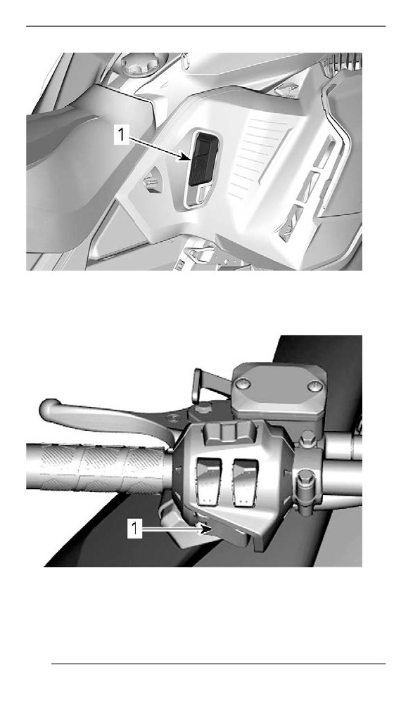
BASIC PROCEDURES
TYPICAL
1. Reverse lever
Models with Start / RER button
1. Start / RER button
4. Wait until reverse beeper sounds, then gently depress throttle
lever.
182
BASIC PROCEDURES
WARNING
The reverse speed is not limited. Always proceed with caution
as fast reverse could result in loss of vehicle stability. Come to
complete stop before activating the reverse. Always remain
seated and apply the brake before shifting. Ensure the path be-
hind is clear of obstacles or bystanders before proceeding.
Shifting in Forward from Reverse
1. Bring vehicle to a complete stop.
2. Apply and hold brake.
3. Press and release the RER button or reverse lever.
4. Apply throttle slowly and evenly. Allow drive pulley to engage then
accelerate carefully.
Shuttiing Off the Engine
Release throttle lever and wait until engine has returned to idle speed.
Shut off the engine using either the emergency engine stop switch or
by pulling off the tether cord cap from the engine cut-off switch.
WARNING
Always remove the tether cord cap from engine cut-off switch
when vehicle is not in operation in order to prevent accidental
engine starting or to avoid unauthorized use by children or
others or theft.
183
RIDING CONDITIONS AND YOUR
SNOWMOBILE
Altitude
At factory, your snowmobile was calibrated to be used within an alti-
tude range (relative to sea level).
A new snowmobile has a tag attached to the handlebar indicating its
calibration. Refer to Safety Information on Vehicle.
If for any reason you don't know your snowmobile calibration, contact
an authorized BRP snowmobile dealer.
If your snowmobile is to be used at an altitude outside the specified
range, have it calibrated accordingly by an authorized BRP snowmo-
bile dealer.
NOTICE
An inappropriate altitude calibration would decrease perform-
ance and may cause serious damage to the snowmobile.
Temperature
The engine management of these engines provides the optimum air/
fuel ratio for all temperatures.
Hard Packed Snow
All models covered in this guide which are equipped with a minimum
track profile of 44 mm (1.75 in) are built for deep snow conditions and
should never be used during a prolonged period of time in marginal or
hard packed snow conditions.
In the event you have to ride in these types of conditions:
- Avoid exceeding a speed of 70 km/h (45 mph) in all conditions
- Avoid hard acceleration (over 75% of throttle)
- Ice scratchers should be applied
- Engine temperature should not exceed 75% on the temperature
gauge.
NOTICE
Running these types of tracks at high speed on a trail, on hard
packed surfaces or on ice puts more stress on the lugs, which
tends to heat up as a result. It also could drastically reduce the
life of specific wear parts. To avoid potential degradation, de-
lamination or damages to the track and wear parts, reduce your
speed and minimize the distance that is being ridden on these
types of surfaces.
184
RIDING CONDITIONS AND YOUR SNOWMOBILE
Vehicles Equipped with Ice Scratchers
Ice scratchers are equipped on the vehicle to increase engine cooling
efficiency, to lubricate and to cool track clips and sliders. They must
be used whenever on ice, hard packed snow, or any conditions that
do not lift enough snow particles into the rear suspension and the
tunnel.
NOTICE
Although it is not recommended to ride a snowmobile equipped
with a high lug profile track on trails or hard packed snow condi-
tions, it is highly suggested to combine idler wheels and ice
scratchers on a vehicle used in these conditions.
IMPORTANT
Ridding in these trail conditions puts the reliability of the track and
its warranty at risk
If equipped with the following track profile heights, never exceed the
recommended sustained vehicle speeds listed.
Track Profile Height
Maximum Sustained Speed
57 mm (2.25 in)
110 km/h (70 MPH)
60 mm (2.36 in)
64 mm (2.52 in)
95 km/h (60 MPH)
75 mm (3 in)
185
TUNE YOUR RIDE
Snowmobile handling and comfort depend upon multiple adjustments.
WARNING
Suspension adjustment could affect vehicle handling. Always
take time to familiarize yourself with the vehicle''s behavior after
any suspension adjustment have been made. Always adjust LH
and RH suspension components to the same setting.
Choice of suspension adjustments vary with carrying load, operator's
weight, personal preference, riding speed and field condition.
NOTE:
Some adjustments may not apply to your snowmobile.
WARNING
Before proceeding with any suspension adjustment, remember:
– Park in a safe place.
– Remove the tether cord cap from the engine cut-off switch.
– Use appropriate lifting device or have assistance to share
lifting stress. If a lifting device is not used, use proper lifting
techniques, notably using your legs force.
– Do not attempt to lift the front or rear of vehicle if it is above
your limits.
– Support front of vehicle off the ground with a suitable device
before adjusting suspension.
– Support rear of vehicle off the ground with a wide-base
snowmobile stand with a rear deflector panel.
– Make sure support device is stable and secure.
The best way to set up the suspension is to customize each adjust-
ment one at a time. Various adjustments are interrelated. It may be
necessary to readjust center spring after adjusting front springs for in-
stance. Test run the snowmobile under the same conditions; trail,
speed, snow, operator riding position, etc. Proceed methodically until
you are satisfied.
Following are guidelines to fine-tune suspension. Use suspension ad-
justment tool provided in the tool kit.
Front Suspension Adjustments
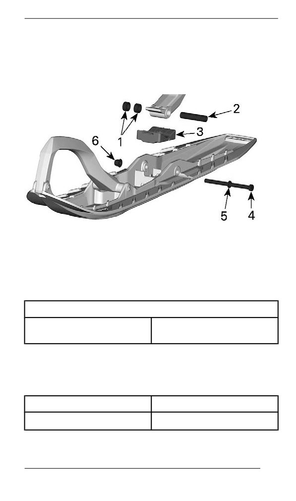
Ski Stance
Skis can be set to three different widths.
To obtain the different widths, place the spacers:
186
TUNE YOUR RIDE
- Inside the skis leg (narrowest ski stance setting: easiest to initiate
turn on sidehills), or
- Outside the skis leg (widest ski stance setting: most stable on cor-
ners), or
- On each side (central setting: best steering accuracy on deep
snow).
1. Spacers
2. Axle
3. Stopper
4. Screw
5. Washer
6. Nut
TIGHTENING TORQUE
48 ± 6 Nm
Ski nut
(35 ± 4 lbf-ft)
Front Springs
Front spring preload has an effect on front suspension firmness.
Front spring preload also has an effect on the steering behavior.
Action
Result
Increasing preload
Firmer front suspension
187
TUNE YOUR RIDE
Action
Result
Higher front end
More precise steering
More bump absorption
capability
Softer front suspension
Lower front end
Decreasing preload
Lighter steering
Less bump absorption
capability
WARNING
Adjust both springs to the same preload. Uneven adjustment
can cause poor handling and loss of stability, and/or control,
and increase the risk of an accident.
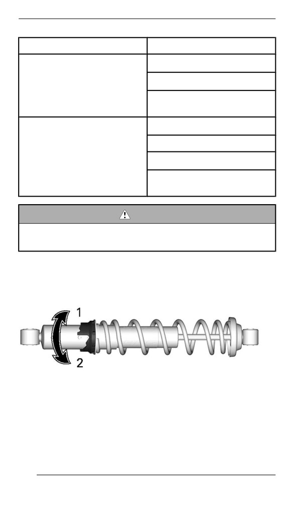
Cam Type Adjuster
Using the suspension adjustment tool provided in the tool kit, turn the
cam to increase or decrease the spring preload.
1. Increase preload
2. Decrease preload
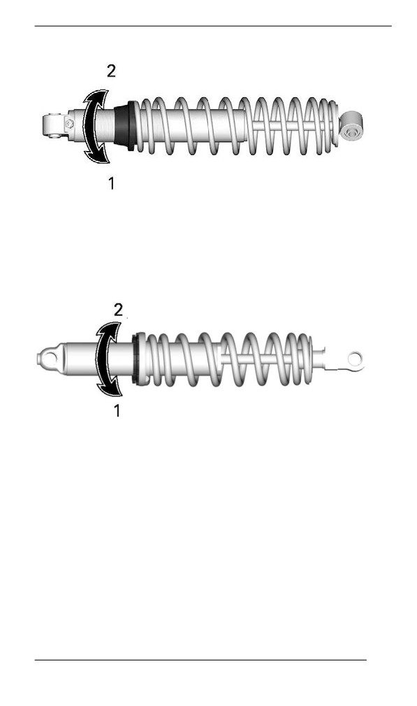
Ring Adjuster – Type 1
Grab and turn the ring and the spring to increase or decrease the
spring preload.
188
TUNE YOUR RIDE
1. Increase preload
2. Decrease preload
Ring Adjuster – Type 2
Grab and turn the ring and the spring to increase or decrease the
spring preload.
1. Increase preload
2. Decrease preload
189
TUNE YOUR RIDE
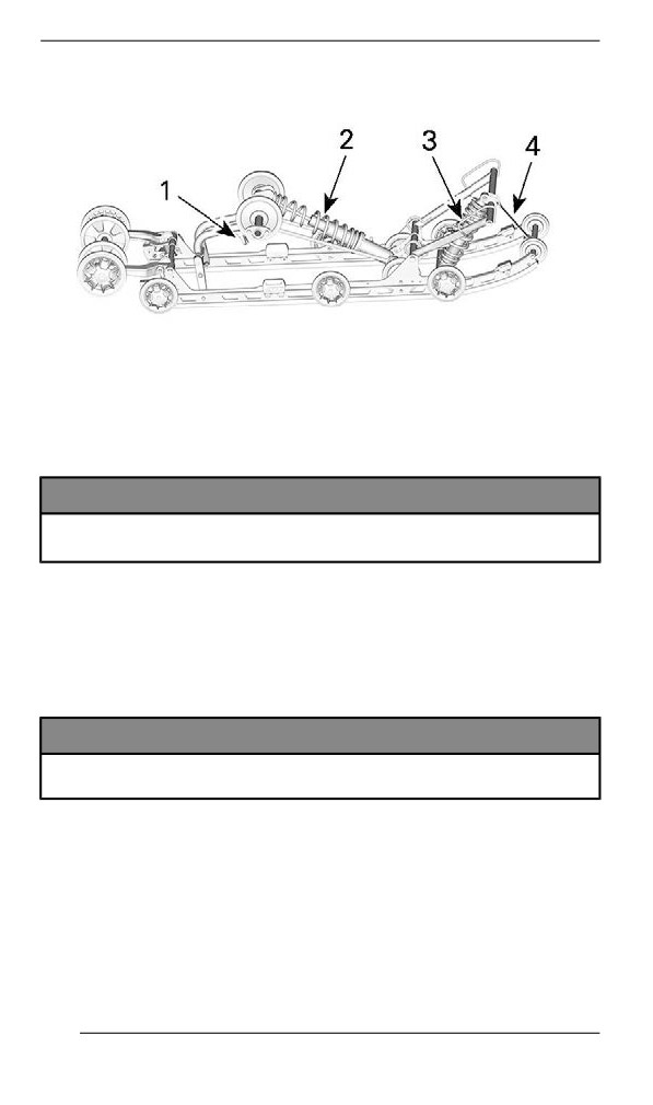
Rear Suspensiion Adjustments
EASYRIDE - ADJUSTABLE COMPONENTS
1. Easy Adjust Handle (if equipped)
2. Rear spring
3. Center spring
4. Stopper strap
NOTICE
Whenever adjusting rear suspension, check track tension and
adjust if necessary.
Stopper Strap – EasyRide Suspension
Stopper strap length has an effect on the amount of weight the center
spring has to carry especially during acceleration, therefore on the
front end uplift.
Stopper strap length also has an effect on center spring travel.
NOTICE
Whenever stopper strap length is changed, track tension must
be checked.
NOTE:
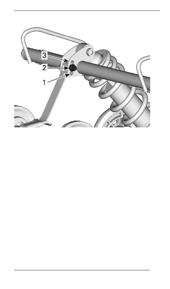
Stopper strap can be set to position 1, 2 or 3. Smaller numbers corre-
spond to a longer strap setting.
190
TUNE YOUR RIDE
STOPPER STRAP POSITIONS
1. Position 1 (longest)
2. Position 2
3. Position 3 (shortest)
When operating the snowmobile in deep snow or hill climbing, it may
be necessary to vary stopper strap length and/or riding position, to
change the angle at which the track rides on the snow. Operator's fa-
miliarity with the various adjustments as well as snow conditions will
dictate the most efficient combination.
Generally, a longer stopper strap setting gives better performance on
a flat landscape and a shorter setting will improve handling in steep hill
climbing and deep snow conditions.
191

TUNE YOUR RIDE
Stopper Strap Setting
Position
Use
Boon docking:
1
- Better bump absorption
- Lighter and easier handling on flat landscape.
2
Standard setting: Best overall setting (general use)
Hill climb:
- Better track attack angle for hill climbing
3
- Less transfer
- Lower ride height
Center Spring
Center spring preload has an effect on steering effort, handling and
bump absorption.
Also, since center spring preload adjustment puts more or less pres-
sure on the front of the track, it has an effect on the performance in
deep snow.
Action
Result
Lighter steering
More bump absorption
capability
Increasing preload
Better deep snow starts
Better deep snow performance
and handling
Heavier steering
Less bump absorption
Decreasing preload
capability
Better trail handling
Cam Type Adjuster
192
TUNE YOUR RIDE
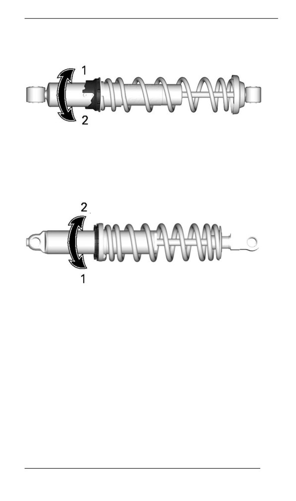
Using the suspension adjustment tool provided in the tool kit, turn the
cam to increase or decrease the spring preload.
1. Increase preload
2. Decrease preload
Ring Type Adjuster
Grab and turn the ring and the spring to increase or decrease the
spring preload.
1. Increase preload
2. Decrease preload
Rear Spring
Rear spring preload has an effect on comfort, ride height and load
compensation.
Also, adjusting rear spring preload shifts more or less weight to the
snowmobile front end. As a result, more or less weight is applied to
the skis. This has an effect on performance in deep snow, steering ef-
fort and handling.
Slight suspension bottoming occurring under the worst riding condi-
tions indicates a good choice of spring preload.
193
TUNE YOUR RIDE
Action
Result
Firmer rear suspension
Higher rear end
Increasing preload
More bump absorption capability
Heavier steering
Softer rear suspension
Lower rear end
Less bump absorption capability
Decreasing preload
Lighter steering
Better deep snow performance and
handling
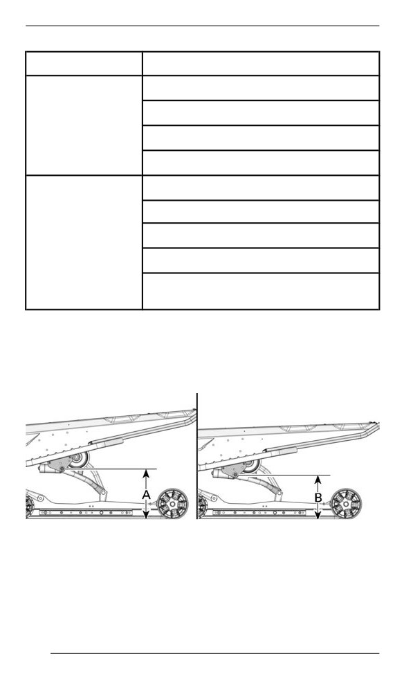
Refer to the following to determine if preload is correct.
- A = Suspension fully extended
- B = Suspension has collapsed with operator, passenger(s) and
load added
- C = Distance between dimension “A” and “B”, see table below
TYPICAL - DISTANCE BETWEEN GROUND AND UPPER REAR
ARM PIVOT
194
TUNE YOUR RIDE
C
What to do
90 to 100 mm (3.6 to 4 in)
No adjustment required
More than
Adjusted too soft. Increase
100 mm (4 in)
preload
Less than
Adjusted too firm. Decrease
90 mm (3.6 in)
preload
NOTE:
If the specification is unattainable with the original springs, visit an au-
thorized BRP snowmobile dealer for other available springs.
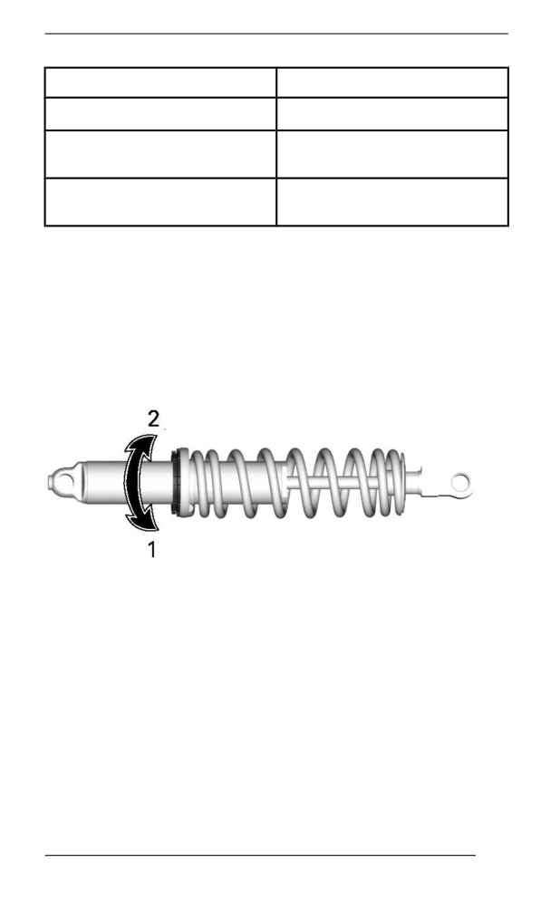
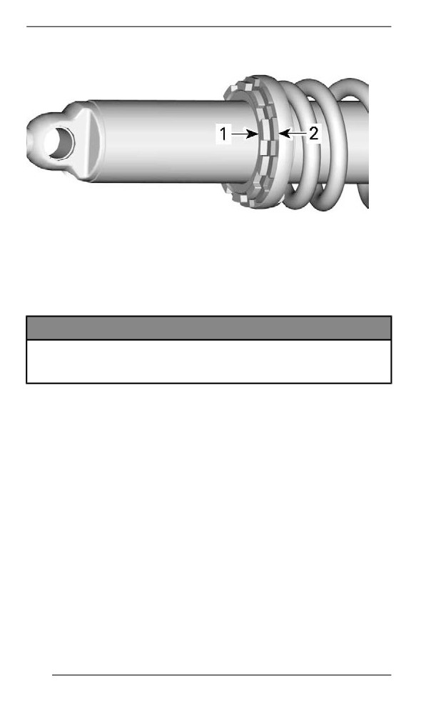
Using the suspension adjustment tool provided in the tool kit, unscrew
the lock ring and turn the adjustment ring to increase or decrease the
spring preload.
Tighten the lock ring when the adjustment is done.
1. Increase preload
2. Decrease preload
195
TUNE YOUR RIDE
1. Locking ring
2. Adjustment ring
Load Capacity Adjustment (If Equipped)
Some EasyRide suspension have an additional adjustment for the
rear suspension load capacity.
NOTICE
The adjustment must always be tightened all the way to either
end of the adjustment. Do not leave the adjustment in between
of these positions, damage can occur.
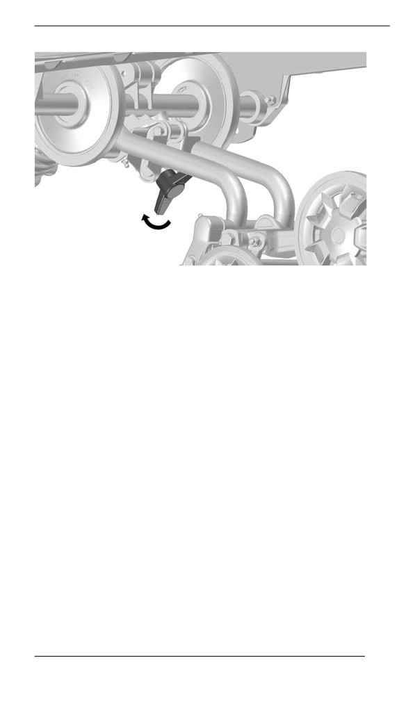
To adjust proceed as follows:
Hard Setting
196
TUNE YOUR RIDE
TURN HANDLE ALL THE WAY CLOCKWISE
- HARDER
SUSPENSION
Turn handle clockwise completely for harder suspension.
NOTE:
Ensure the limiter is touching the rear arm bracket.
197
TUNE YOUR RIDE
Soft Setting
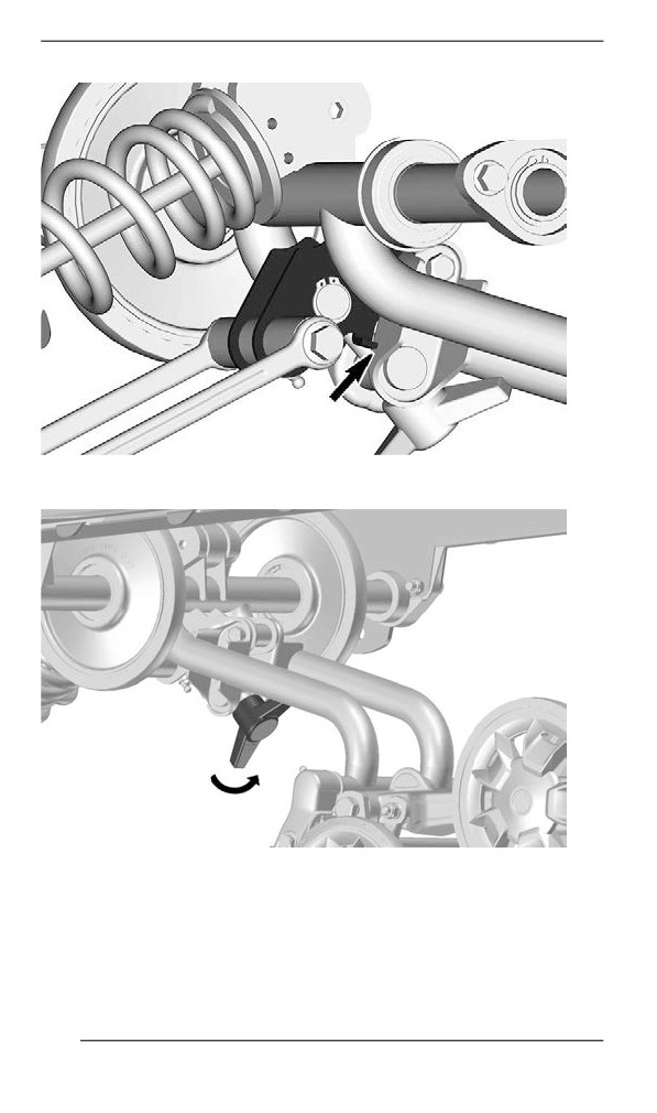
TURN HANDLE ALL THE WAY COUNTERCLOCKWISE
-
SOFTER SUSPENSION
Turn handle counterclockwise completely for softer suspension. (Fac-
tory setting)
198
TUNE YOUR RIDE
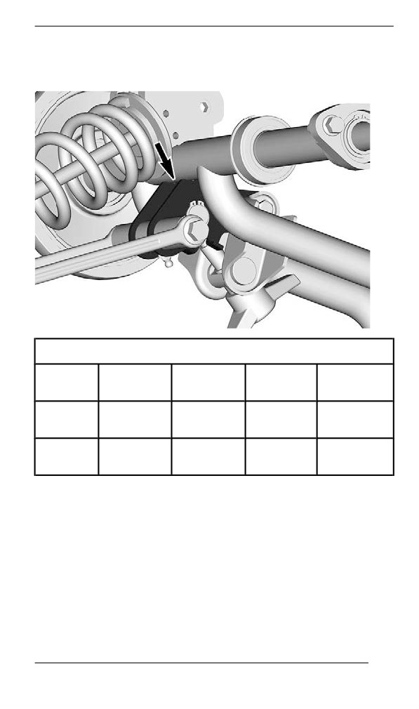
NOTE:
Ensure the limiter is touching the rear arm tube.
Adjustment chart
Comfort
Comfort
Carrying
Hauling
(1-up)
(2-up)
cargo
heavy loads
Soft
X
X
Setting
Hard
X
X
Setting
199
TUNE YOUR RIDE
Adjjustment Tips Accordiing to Vehicle Behavior
Problem
Corrective Measures
Check ski alignment.
-
Reduce front suspension spring
Front suspension darting
preload.
-
Increase center spring preload.
–
Reduce rear spring preload.
Steering feels too heavy
-
Reduce front suspension spring
at steady speeds
preload.
-
Increase center spring preload.
Steering feels too heavy
-
Reduce rear spring preload.
during acceleration
-
Lengthen limiter strap.
Too much ski lift during
-
Shorten limiter strap.
cornering or acceleration
–
Increase rear spring preload.
Rear of snowmobile
-
Reduce rear spring preload.
seems too stiff
Rear of snowmobile
-
Increase rear spring preload.
seems too soft
-
Increase rear spring preload.
Rear suspension is
–
Increase center spring preload.
frequently bottoming
–
Lengthen limiter strap.
-
Reduce center spring preload.
Snowmobile seems to
–
Increase rear spring preload.
pivot around its center
-
Increase front suspension spring
preload.
-
Shorten limiter strap.
-
Lengthen limiter strap.
Track spins too much at
-
Reduce rear spring preload.
start
–
Increase center spring preload.
200
MAINTENANCE
201
MAINTENANCE SCHEDULE
Maintenance is very important to keep your vehicle in safe operating
condition. The vehicle should be serviced as per the maintenance
schedule.
Proper maintenance is the owner’s responsibility. A warranty claim
may be denied if, among other things, the owner or operator caused
the problem through improper maintenance or use.
Perform periodic checks and follow the maintenance schedule. The
maintenance schedule does not exempt the pre-ride inspection.
WARNING
Failure to properly maintain the vehicle according to the main-
tenance schedule and procedures can make it unsafe to
operate.
EPA Regullatiion - Canadiian and USA Vehiiclles
A repair shop or person of the owner''s choosing may maintain,
replace, or repair emission control devices and systems. These in-
structions do not require components or service by BRP or authorized
BRP snowmobile dealers.
Although an authorized BRP snowmobile dealer has an in-depth tech-
nical knowledge and tools to service your vehicle, the emission-related
warranty is not conditioned on the use of an authorized BRP snowmo-
bile dealer or any other establishment with which BRP has a commer-
cial relationship.
Proper maintenance is the owner’s responsibility. A warranty claim
may be denied if, among other things, the owner or operator caused
the problem through improper maintenance or use.
For emission-related warranty claims, BRP is limiting the diagnosis
and repair of emission-related parts to the authorized BRP snowmo-
bile dealers. For more information, please refer to the US EPA Emis-
sions PERFORMANCE WARRANTY contained in the warranty
section.
You must follow the instructions for fuel requirements in the fueling
section of this manual. Even if gasoline containing greater than ten
volume percent ethanol is readily available, the US EPA issued a pro-
hibition against the use of gasoline containing greater than 10 vol %
ethanol that applies to this vehicle. The use of gasoline containing
greater than 10 vol% ethanol with this engine may harm the emission
control system.
202
MAINTENANCE SCHEDULE
Traill/ Crossover/ Utillity Usage
Whether your vehicle is a Trail, Crossover, or Utility model, these
types of usage require maintenance tasks to be performed between
the regular yearly intervals. These are identified as A + in the chart
below.
If you regularly ride in trails, explore the countryside, or work with
your snowmobile, follow the A+ Trail / Crossover / Utility interval and
perform the tasks outlined in the chart below.
Extreme Cold Condition
An engine that is frequently operated at or below an ambient tempera-
ture of -25 °C (-13 °F) will require an increase in service and mainte-
nance schedule.
Any combustion engine operated at these low ambient temperature
will collect an increased amount of condensation at every startup/
warm-up.
Since the engine is not reaching operating temperatures for extended
periods of time, the oil is starting to be strongly diluted with water and
gas residue (more water content).
An engine needs to reach operating temperature, in order to be able
to evaporate condensate out of the oil.
If daily usage (work or leisure driving cycle) is similar to those men-
tioned below, BRP strongly recommends changing the oil at least
once a month.
Parameters of an increase in service and maintenance schedule:
- Engine not reaching the proper operating temperature during nor-
mal daily usage
- Multiple starts and stops without reaching operating temperature
- Short idle periods
- Low RPM driving cycle in short distances without reaching operat-
ing temperature.
NOTE:
BRP strongly recommends the installation of a block heater to help
warm up the liquids, this will also help to extend the oil lifetime.
203
MAINTENANCE SCHEDULE
Maiintenance Schedulle
Make sure to perform proper maintenance at recommended intervals
as indicated in the tables.
The maintenance chart indicates the items needing to be addressed
based on 2 criteria, whichever happens first:
- Calendar time
- Odometer reading.
Your driving habits determines the factors you shall adhere too. For
example:
- Someone who uses their vehicle every other weekend trail riding
with friends would most likely follow the odometer reading to de-
termine the frequency of his maintenance.
- Someone who uses their vehicle seldomly over the year or only on
a few occasions would follow the calendar time to determine the
frequency of his maintenance.
IMPORTANT: The following tables show the appropriate mainte-
nance application for the first 3 years. For subsequent years, repeat
the same pattern alternatively.
Maiintenance Overviiew
Calendar
Trail/ Cross
Odometer
Time
Over/ Utility
Every
1500 km (1000 mi)
A+
Month
1 Year
3000 km (2000 mi)
A
Every
4500 km (3000 mi)
A+
Month
2 Years
6000 km (4000 mi)
A and B
Every
7500 km (5000 mi)
A+
Month
204
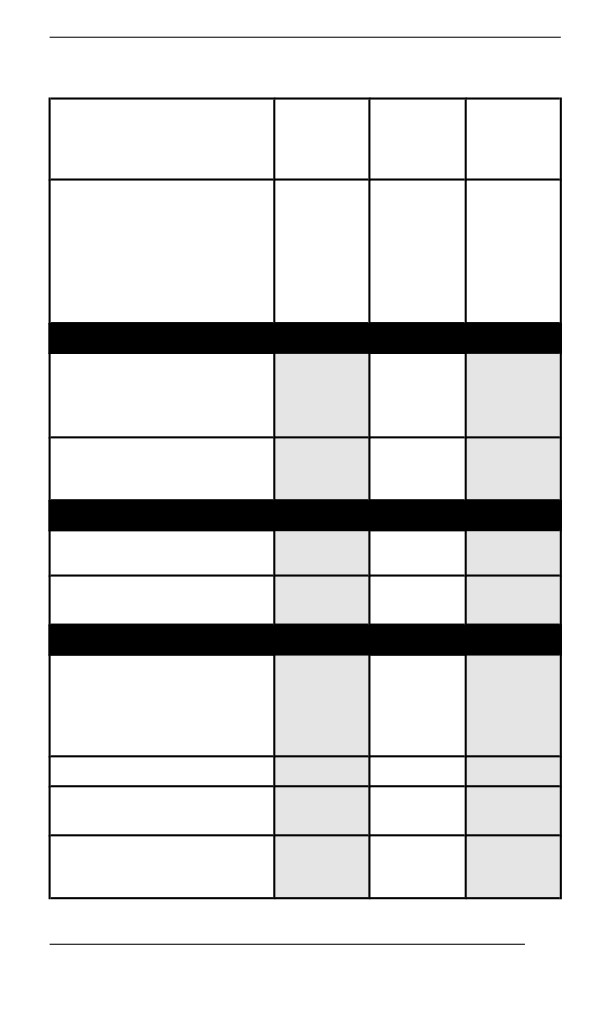
MAINTENANCE SCHEDULE
600 ACE/ 900 ACE Engines
TRAIL /
CROSSOVER
A+
A
B
/ UTILITY
Every
Every 2
A=Adjust
Every
month
years
C=Clean
year
or
or
I=Inspect
or
1500
6000
L=Lubricate
3000 km
km
km
R=Replace
(2000
(1000
(4000
T=Torque
mi)
mi)
mi)
Air and Fuel Delivery
Fuel components (fuel
cap, hoses, clamps and
I
tank fixation) and
function
R
In-line fuel filter
Every 5
years
Body and Chassis
Body panels and
I, T
hardware
Pivots, latches, hinges
L
and key barrels
Engine and Cooling
Engine cooling
components (coolant
concentration, coolant
I, A
level, hose condition,
clamps, leaks)
Engine oil and oil filter
R
Engine seals and
I
gaskets
R
Spark plugs
Every 3
years
205
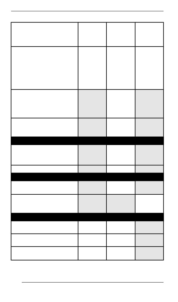
MAINTENANCE SCHEDULE
TRAIL /
CROSSOVER
A+
A
B
/ UTILITY
Every
Every 2
A=Adjust
Every
month
years
C=Clean
year
or
or
I=Inspect
or
1500
6000
L=Lubricate
3000 km
km
km
R=Replace
(2000
(1000
(4000
T=Torque
mi)
mi)
mi)
or
10 000
km
(6000
mi)
R
Engine coolant
Every 5
years
Exhaust and Emissions
Exhaust components
(gaskets, pipes, muffler
I
condition, leaks)
Exhaust manifold
T
Brake
Brake components and
I, L
function
R
Brake fluid
Every
2
years
Drive
Chaincase drive chain
A
A
tension
Gearbox / chaincase oil
I
I
level
Track alignment and
A
I, A
tension
206
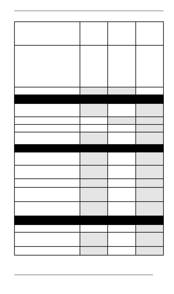
MAINTENANCE SCHEDULE
TRAIL /
CROSSOVER
A+
A
B
/ UTILITY
Every
Every 2
A=Adjust
Every
month
years
C=Clean
year
or
or
I=Inspect
or
1500
6000
L=Lubricate
3000 km
km
km
R=Replace
(2000
(1000
(4000
T=Torque
mi)
mi)
mi)
Gearbox / chaincase oil
R
Continuously Variable Transmission (CVT)
CVT components and
I,
C, L
function
CVT drive belt condition
I
CVT drive belt tension
A
A
Drive pulley retaining
T
screw
Electrical
Battery connections and
I
condition
Electrical harness
I
routing
Headlight aim
A
Modules and applicable
I
software updates
Operation of control
I
switches and lighting
Steering and Controls
Ski runners
I
I
Gearbox position lever
I, A
operation
Steering alignment
I, A
207
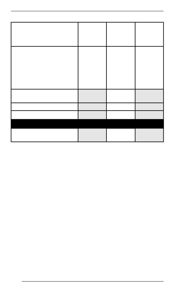
MAINTENANCE SCHEDULE
TRAIL /
CROSSOVER
A+
A
B
/ UTILITY
Every
Every 2
A=Adjust
Every
month
years
C=Clean
year
or
or
I=Inspect
or
1500
6000
L=Lubricate
3000 km
km
km
R=Replace
(2000
(1000
(4000
T=Torque
mi)
mi)
mi)
Steering components
I
and function
Throttle cable
A
Throttle operation
I
Suspension
Suspension components
I, L
and function
208
MAINTENANCE SCHEDULE
900 ACE Turbo/ R
TRAIL /
CROSSOVER
A+
A
B
/ UTILITY
Every
Every 2
A=Adjust
Every
month
years
C=Clean
year
or
or
I=Inspect
or
1500
6000
L=Lubricate
3000 km
km
km
R=Replace
(2000
(1000
(4000
T=Torque
mi)
mi)
mi)
Air and Fuel Delivery
Fuel components (fuel
cap, hoses, clamps and
I
tank fixation) and
function
R
In-line fuel filter
Every 5
years
Body and Chassis
Body panels and
I, T
hardware
Pivots, latches, hinges
L
and key barrels
Engine and Cooling
Engine cooling
components (coolant
concentration, coolant
I, A
level, hose condition,
clamps, leaks)
Engine oil and oil filter
R
Engine seals and
I
gaskets
R
Spark plugs
Every 3
years
209
MAINTENANCE SCHEDULE
TRAIL /
CROSSOVER
A+
A
B
/ UTILITY
Every
Every 2
A=Adjust
Every
month
years
C=Clean
year
or
or
I=Inspect
or
1500
6000
L=Lubricate
3000 km
km
km
R=Replace
(2000
(1000
(4000
T=Torque
mi)
mi)
mi)
or
10 000
km
(6000
mi)
R
Engine coolant
Every 5
years
Exhaust and Emissions
Exhaust components
(gaskets, pipes, muffler
I
condition, leaks)
Exhaust manifold
T
R
Every 3
years
or
Turbo exhaust gasket
10 000
km
(6000
mi)
Brake
Brake components and
I, L
function
R
Brake fluid
Every 2
years
210
MAINTENANCE SCHEDULE
TRAIL /
CROSSOVER
A+
A
B
/ UTILITY
Every
Every 2
A=Adjust
Every
month
years
C=Clean
year
or
or
I=Inspect
or
1500
6000
L=Lubricate
3000 km
km
km
R=Replace
(2000
(1000
(4000
T=Torque
mi)
mi)
mi)
Drive
Chaincase drive chain
A
A
tension
Gearbox / chaincase oil
I
I
level
Track alignment and
A
I, A
tension
Gearbox / chaincase oil
R
Continuously Variable Transmission (CVT)
CVT components and
I, C, L
function
CVT drive belt condition
I
CVT drive belt tension
A
A
Drive pulley retaining
T
screw
Electrical
Battery connections and
I
condition
Electrical harness
I
routing
Headlight aim
A
Modules and applicable
I
software updates
Operation of control
I
switches and lighting
211
MAINTENANCE SCHEDULE
TRAIL /
CROSSOVER
A+
A
B
/ UTILITY
Every
Every 2
A=Adjust
Every
month
years
C=Clean
year
or
or
I=Inspect
or
1500
6000
L=Lubricate
3000 km
km
km
R=Replace
(2000
(1000
(4000
T=Torque
mi)
mi)
mi)
Steering and Controls
Ski runners
I
I
Gearbox position lever
I, A
operation
Steering alignment
I, A
Steering components
I
and function
Throttle cable
A
Throttle operation
I
Suspension
Suspension components
I, L
and function
212
MAINTENANCE PROCEDURES
This section includes instructions for basic maintenance procedures.
WARNING
Turn off the engine, remove tether cord cap and follow these
maintenance procedures when performing maintenance. If you
do not follow proper maintenance procedures you can be in-
jured by hot parts, moving parts, electricity, chemicals or other
hazards.
WARNING
Should removal of a locking device be required (e.g. lock tabs,
self-locking fasteners, etc.) when undergoing disassembly/as-
sembly, always replace with a new one.
Engine Coollant
WARNING
Never open coolant tank cap when engine is hot.
Engine Coolant Level Verification
Open the RH side panel, see Body and Seat.
Check coolant level at room temperature. Liquid should be at cold lev-
el line of coolant tank.
NOTE:
When checking level at low temperature it may be slightly lower than
the mark.
If additional coolant is necessary or if entire system has to be refilled,
refer to an authorized BRP snowmobile dealer, repair shop or person
of your own choosing.
213