CLAAS DOMINATOR 150 / 140 / 130. Operator’s Manual - page 22
13 Maintenance
13.9 Hydraulic system
67089
13.9 Hydraulic system
86485
13.9.1 Checking the hydraulic system oil level
- Park the machine on level ground.
- Lower the feeder as far as possible.
- Lower the reel all the way.
- Swing in unloading auger tube.
- Observe the general warnings at the beginning of
the "Maintenance" chapter.
Caution!
Machine operation with unpermitted or pol-
luted lubricants.
Machine damage.
- Ensure a clean environment.
- Use suitable and clean tools.
- Use permitted lubricants.
- Lubricants must be free of pollution.
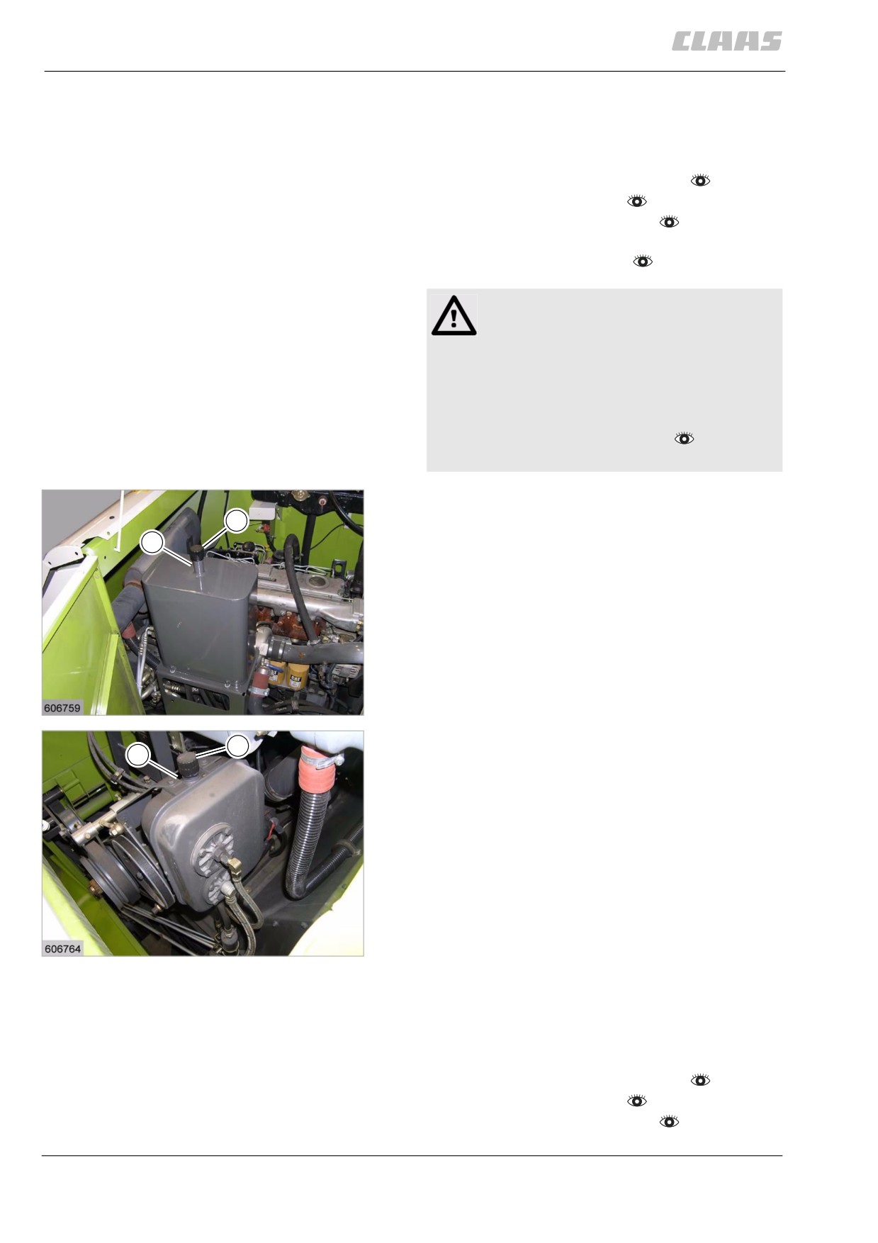
- Read the oil level on the gauge rod (1).
1
The oil must not be higher than the FULL mark (maxi-
A
mum) and must not drop below the SAFE mark
(minimum) on the oil dipstick.
- If necessary, refill with oil at (A).
111
DOMINATOR 150 / 140
23377
1
A
112
DOMINATOR 130
23382
86487
13.9.2 Changing the hydraulic system oil / oil
filter / fresh air filter element
DOMINATOR 150 / 140
- Park the machine on level ground.
- Lower the feeder as far as possible.
- Lower the reel all the way.
– Swing in unloading auger tube.
340
13 Maintenance
13.9 Hydraulic system
67089
-
Observe the general warnings at the beginning of
the "Maintenance" chapter.
Warning!
Contact with hot liquids or machine parts.
Danger of burns
- Wear suitable protective clothing.
- Let liquids or machine parts cool down.
- Comply with instructions.
Environment!
Lubricants and fuels end up in the
environment.
Environmental pollution.
- Lubricants and fuels must be collected
and stored in suitable containers and dis-
posed of in a way that is harmless to the
environment and in accordance with
existing anti-pollution regulations.
WARNING:
Use of unpermissible spare parts or
lubricants.
Machine damage or increased wear.
- Spare parts and lubricants must at least
comply with the technical standards
required by the manufacturer of the
implement!
- The use of genuine CLAAS spare parts
and lubricants is recommended.
-
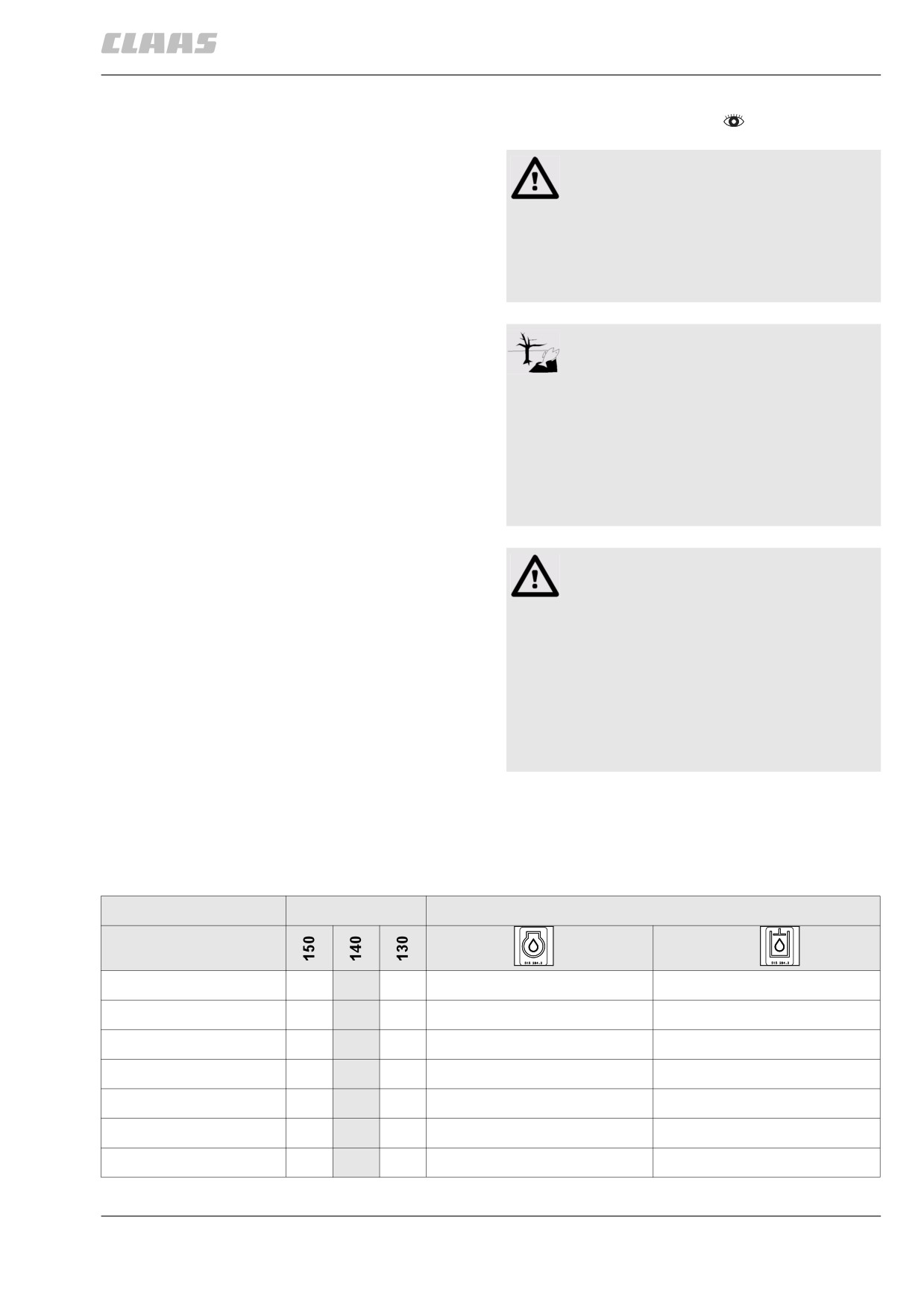
Identify the position of the hydraulic oil drain noz-
zle in the table and on the machine. The oil drain
nozzle is marked on the machine by a hydraulic oil
decal.
DOMINATOR
Position of drain hose
Engine type
Engine oil
Hydraulic oil
CATERPILLAR C-6.6
•
left machine side, inside
left machine side, outside
CATERPILLAR C-6.6
•
left machine side, inside
left machine side, outside
CATERPILLAR C-6.6
•
left machine side, inside
on the steering cylinder
CATERPILLAR 3056 E
•
right machine side
left machine side, inside
CATERPILLAR 3056 E
•
right machine side
left machine side, inside
CATERPILLAR 3056 E
•
right machine side
on the steering cylinder
PERKINS 1006-6T
•
right machine side
on the steering cylinder
341
13 Maintenance
13.9 Hydraulic system
67089
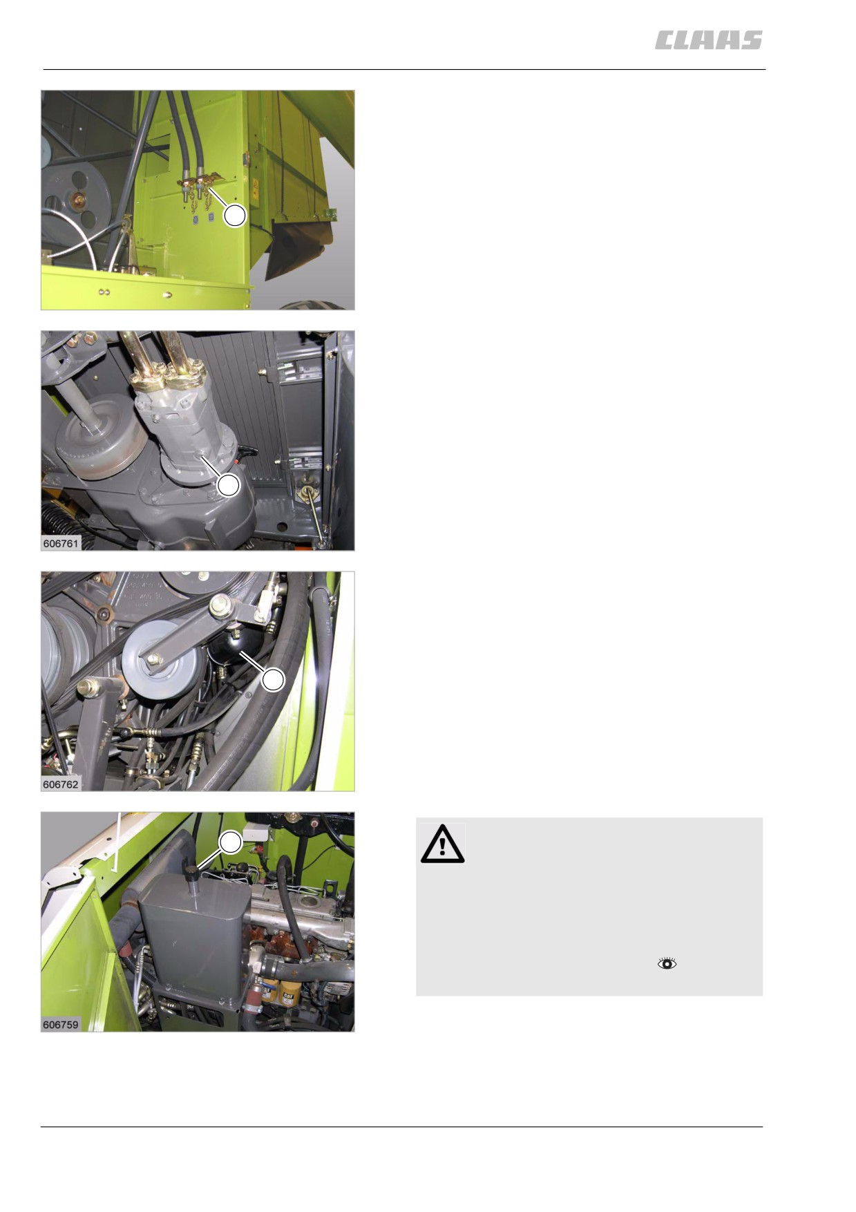
- Fit a suitable hose on the hydraulic oil drain
nozzle.
- Slacken off nut (1) slightly.
- Collect the used oil in a sufficiently large
container.
- Tighten nut (1).
- Remove hose.
1
113
left machine side
29543
- Unscrew bolt (1).
- Collect the used oil in a sufficiently large
container.
- Turn in screw (1).
1
114
23379
- Remove oil filter (1).
Collect escaping oil in a suitable container.
- Screw on a new oil filter.
1
115
23380
Caution!
1
Machine operation with unpermitted or pol-
luted lubricants.
Machine damage.
- Ensure a clean environment.
- Use suitable and clean tools.
- Use permitted lubricants.
- Lubricants must be free of pollution.
- Unscrew fresh air filter element (1).
116
23377
- Fill new hydraulic oil into the oil tank.
Use a filling screen!
Fill in hydraulic oil slowly!
- Correct oil level.
342
13 Maintenance
13.9 Hydraulic system
67089
- Start the machine.
- Start the diesel engine.
- Let diesel engine run at min. no-load speed for
about 10 seconds.
- Stop the diesel engine.
- Observe the general warnings at the beginning
of the "Maintenance" chapter.
- Check the hydraulic tank oil level and top up if
necessary.
- Repeat this process until topping up is not nec-
essary any more following a check.
-
Start the machine.
–
Start the diesel engine.
–
Set gearbox to neutral. (No gear engaged).
–
Let machine run with the ground speed control
lever halfway actuated for about 2 minutes in both
directions of travel.
-
Stop the diesel engine.
–
Observe the general warnings at the beginning of
the "Maintenance" chapter.
-
Check the hydraulic system oil level and top up if
necessary.
-
Screw on a new fresh air filter element (1).
86525
13.9.3 Changing the hydraulic system oil / oil
filter / fresh air filter element DOMINATOR 130
To change the hydraulic oil of the lift hydraulic system,
turn the steering wheel to pump the oil out of the
hydraulic oil tank with the engine stopped.
- Park the machine on level ground.
- Lower the feeder as far as possible.
- Lower the reel all the way.
- Swing in unloading auger tube.
- Observe the general warnings at the beginning of
the "Maintenance" chapter.
Warning!
Contact with hot liquids or machine parts.
Danger of burns
- Wear suitable protective clothing.
- Let liquids or machine parts cool down.
- Comply with instructions.
343
13 Maintenance
13.9 Hydraulic system
67089
Environment!
Lubricants and fuels end up in the
environment.
Environmental pollution.
- Lubricants and fuels must be collected
and stored in suitable containers and dis-
posed of in a way that is harmless to the
environment and in accordance with
existing anti-pollution regulations.
WARNING:
Use of unpermissible spare parts or
lubricants.
Machine damage or increased wear.
- Spare parts and lubricants must at least
comply with the technical standards
required by the manufacturer of the
implement!
- The use of genuine CLAAS spare parts
and lubricants is recommended.
-
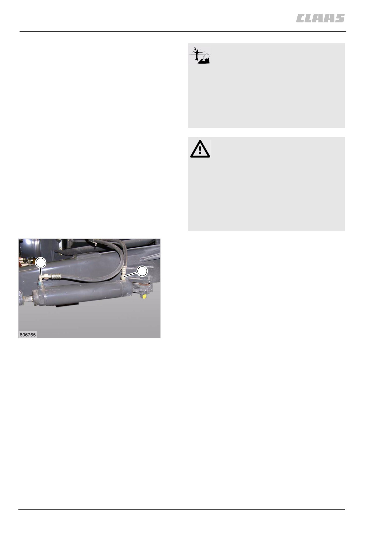
Unscrew one hydraulic hose (1 or 2) from the
steering cylinder and place the end into a suffi-
ciently large container.
1
-
Collect the used oil in a sufficiently large
2
container.
-
Turn the steering wheel in the appropriate direc-
tion until all the oil has been pumped out of the
system.
-
Connect the hydraulic hose to the steering cylin-
der again.
117
23383
344
13 Maintenance
13.9 Hydraulic system
67089
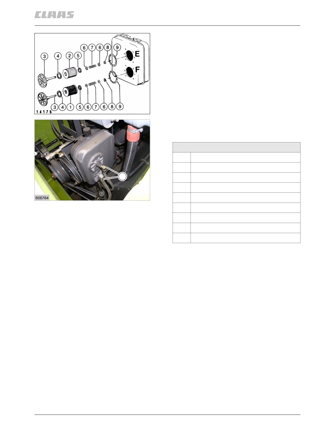
- Unscrew hydraulic lines at position (A).
- Unscrew filter head (3), remove lock washer (8)
and screen filter (1).
- Wash out the screen insert element (1) with ben-
zene and blow out with compressed air.
Always replace damaged screen filters and
seals (9).
- Fit cleaned screen filter (1) and lock washer (8) on
filter head (3) and screw it on.
- Unscrew filter head (3), remove lock washer (8)
and paper filter cartridge (2).
118
Always replace paper filter cartridge (2) and seals.
23384
- Fit new paper filter cartridge (2) and lock
washer (8) on filter head (3) and screw it on.
- Screw on hydraulic lines at position (A).
Hydraulic oil filter, exploded view
1
Screen insert
2
Paper filter cartridge / screen insert
A
3
Filter head
4
Felt ring
119
5
Felt ring
23382
6
Washer 13
7
Compression spring
8
Lock washer
9
Gasket
345
13 Maintenance
13.9 Hydraulic system
67089
1
Caution!
Machine operation with unpermitted or pol-
luted lubricants.
Machine damage.
- Ensure a clean environment.
- Use suitable and clean tools.
- Use permitted lubricants.
- Lubricants must be free of pollution.
-
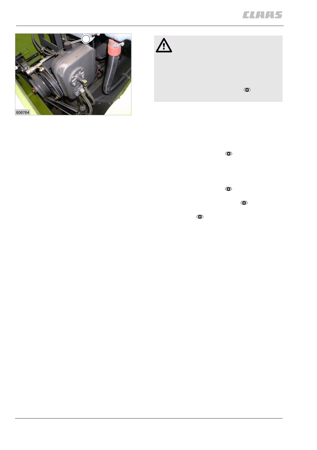
Unscrew fresh air filter element (1).
120
23382
–
Fill new hydraulic oil into the oil tank.
Use a filling screen!
Fill in hydraulic oil slowly!
-
Correct oil level.
- Start the machine.
- Start the diesel engine.
- Let the diesel engine run at lower maximum no-
load speed.
- Turn the steering wheel up to the stop in both
directions several times.
- Stop the diesel engine.
- Observe the general warnings at the beginning
of the "Maintenance" chapter.
- Check the hydraulic tank oil level and top up if
necessary.
- Repeat this process until topping up is not nec-
essary any more following a check.
-
Screw on a new fresh air filter element (1).
346
13 Maintenance
13.10 Electric system / Electronics
67089
13.10 Electric system / Electronics
85765
13.10.1 Checking the battery electrolyte level
- Observe the general warnings at the beginning of
the "Maintenance" chapter.
Environment!
Handling of used batteries.
Environmental pollution.
- Dispose of old batteries in a way that is
harmless to the environment and in
accordance with existing anti-pollution
regulations.
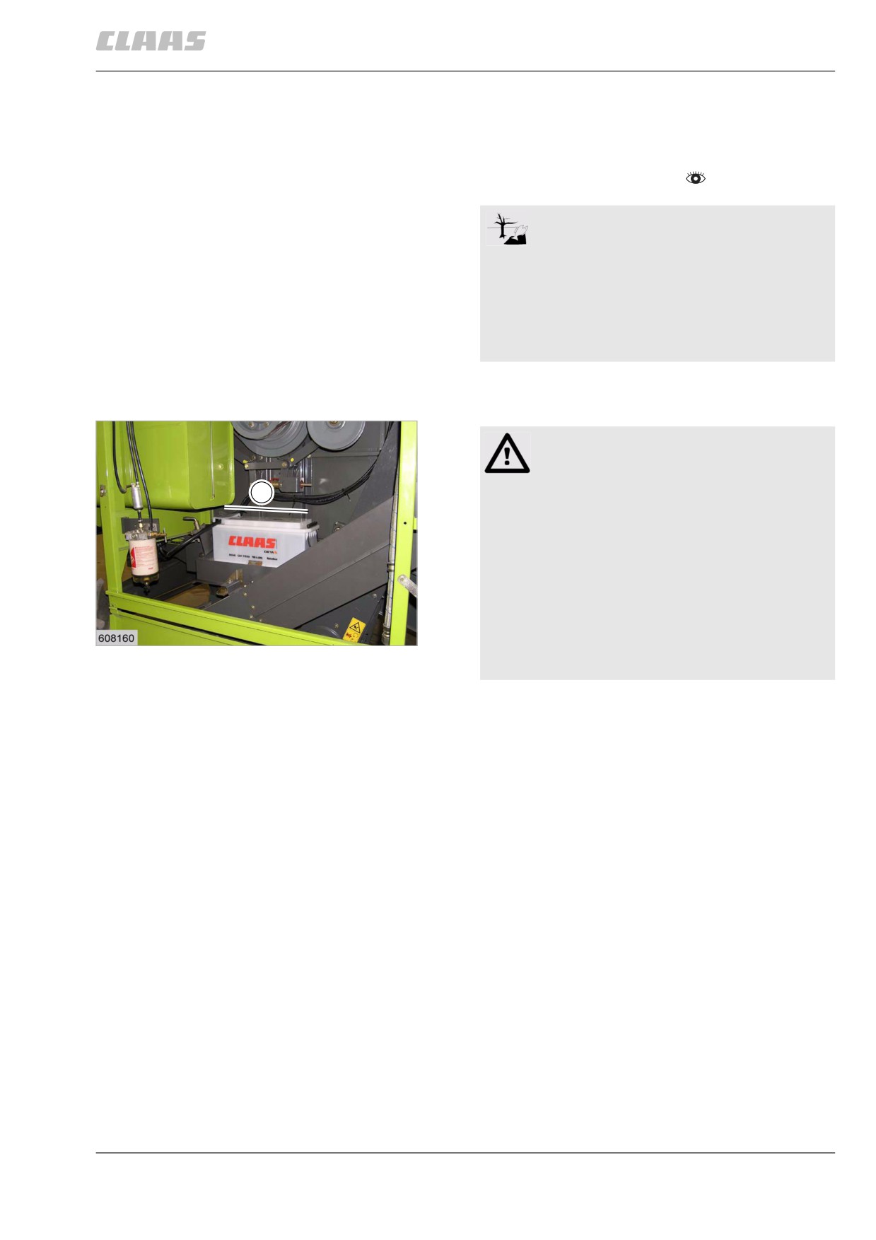
The battery can be accessed from the discharge and
cooling system compartment.
Danger!
Incorrect handling of batteries.
1
Death or serious injury.
- Be careful with battery gases, they are
highly explosive.
- Avoid sparks and naked flames in the
vicinity of a battery!
- Remove the covers (vent caps) when
recharging the battery to prevent the
accumulation of highly explosive gases.
121
23496
- Be careful when handling battery acids,
they are caustic.
- Unscrew all covers (1).
- Check electrolyte level.
The electrolyte level must be about 10 mm above
the inside plates.
- Top up distilled water if required.
- Fit all covers (1).
- Fit safety device.
- Close the cover.
347
13 Maintenance
13.11 Cab / Operator's platform
67089
13.11 Cab / Operator's platform
86809
13.11.1 Cleaning / changing the cab air filter
-
Observe the general warnings at the beginning of
the "Maintenance" chapter.
Warning!
Incorrectly installed or defective air filter.
Dust getting into the cab.
Dust is inhaled and causes damage to your
health.
- Ensure tight seat of filter.
- Replace defective air filters immediately.
-
Use a suitable ladder on the right machine side.
Danger!
Danger of falling!
Death or serious injuries!
- Use a suitable ladder.
-
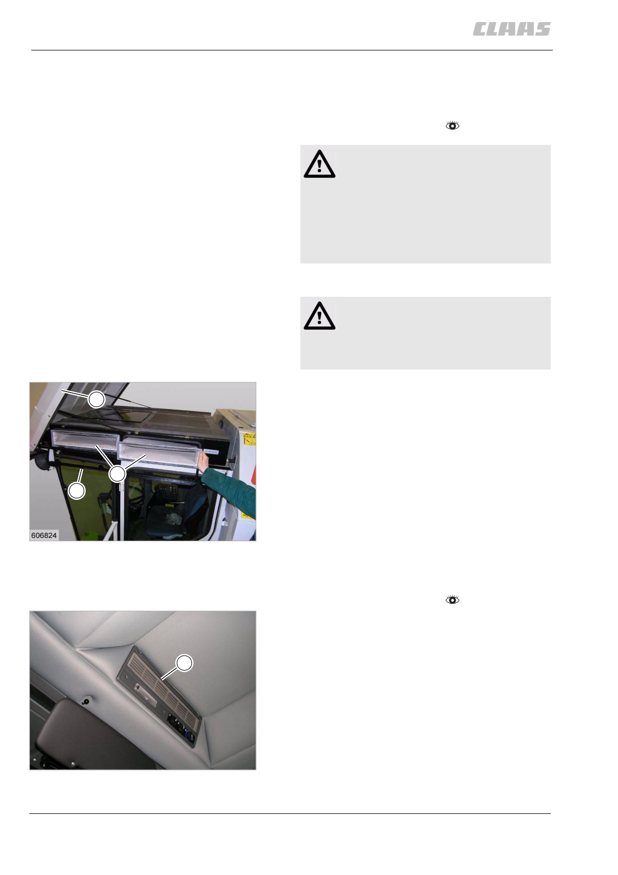
Open cab roof (1).
1
-
Open frame (2).
–
Remove filter (3).
–
Clean filter surface by vacuum cleaning, knocking
on it or blowing off with compressed air.
-
Replace damaged filters and sealing profiles.
3
–
Close cab roof (1).
2
122
23853
86833
13.11.2 Cleaning the cab recirculation air filter
- Observe the general warnings at the beginning of
the "Maintenance" chapter.
- Remove the recirculation air grille (1).
- Clean filter surface by vacuum cleaning, knocking
on it or blowing off with compressed air.
- Replace damaged filters.
1
- Install recirculation air grille (1).
123
29686
348
13 Maintenance
13.11 Cab / Operator's platform
67089
86814
13.11.3 Cleaning the cab roof units
-
Observe the general warnings at the beginning of
the "Maintenance" chapter.
Note!
Dirty units will have reduced heating and cool-
ing capacity.
Uneconomic use of machine.
- Observe the specified maintenance
intervals.
- Clean the units more frequently when
working in very dusty conditions.
WARNING:
Cleaning of sensitive components with exces-
sive levels of compressed air or other cleaning
means.
Component damage.
- Never direct the compressed air jet
directly to sensitive components such as
cooling fins or filter elements.
- Never use a steam jet cleaner for
cleaning.
-
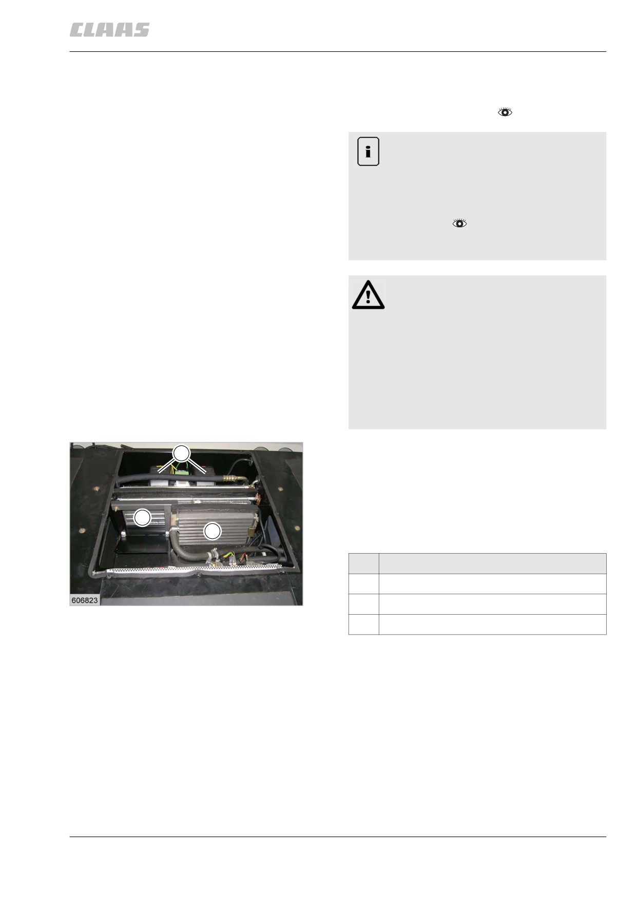
Open cab roof (1).
2
–
Unscrew cover from cab.
–
Blow out evaporator (3) and hot-water radiator (4)
with compressed air (5 bar max.).
-
Replace damaged seals (1) beneath the cover.
3
-
Bolt down cover from cab.
4
-
Close cab roof (1).
Designation
2
Fan
124
3
Evaporator
23854
4
Radiator
349
13 Maintenance
13.11 Cab / Operator's platform
67089
86819
13.11.4 Putting the air conditioner into
operation
To prevent compressor damage on machines with an
air conditioner, the air conditioner should be put back
into operation after an extended standstill period.
This putting into operation ensures that the oil is dis-
tributed accordingly in the air conditioner.
- Start the diesel engine and let it run at idle
speed.
- Switch the air conditioner on.
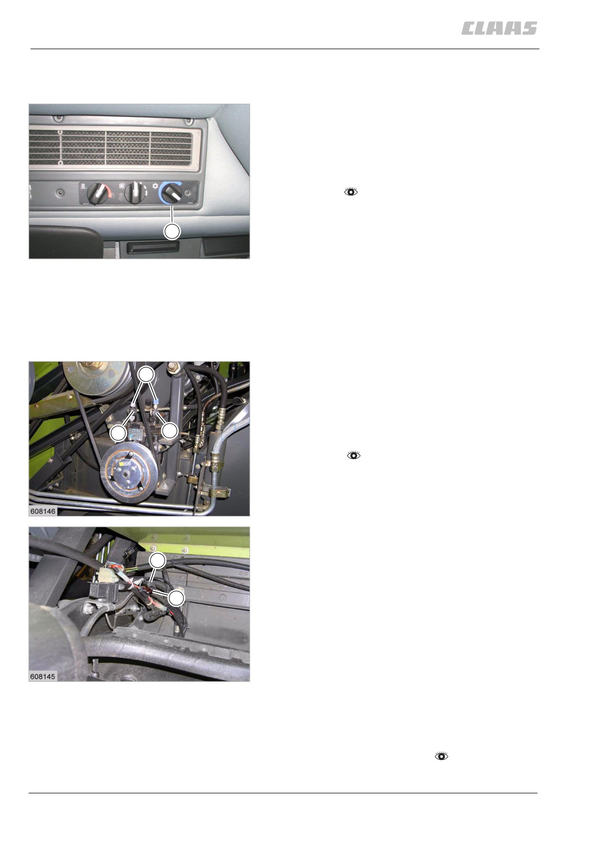
- Set the temperature controller (1) to the lowest
1
temperature.
- Let machine run in idle speed for about 5-
125
10 minutes.
29685
The air conditioner can now be operated again as
usual.
86828
13.11.5 Precautions for protecting the air con-
ditioner during extended standstill periods -
DOMINATOR 130 with York compressor
- In the cold season, switch on the cab heater and
3
heat up the cab to around +21 °C.
On combines with air conditioner without heater,
possibly use an electric heater or similar to raise
the cab temperature to +21 °C.
2
- Operate the air conditioner for five to ten minutes.
1
- Shut off the air conditioner and switch off the
engine.
- Close the compressor service valves (1 and 2).
Screw on the caps (3) tightly.
- Ensure that the blade-type fuse (4) in the current-
126
carrying line to the electro-magnetic clutch of the
19297
compressor is definitely removed.
Running the compressor with the service valves
closed will result in damage to the compressor.
5
- Now fit the cap (5) so no water can penetrate into
the compressor.
Note: The blade-type fuse is located between the
4
engine and the grain tank.
127
19298
86837
13.11.6 Checking the air conditioner refriger-
ant moisture saturation
- Observe the general warnings at the beginning of
the "Maintenance" chapter.
350
13 Maintenance
13.11 Cab / Operator's platform
67089
Danger!
Refrigerant.
Death or serious injury.
- Only have authorised and qualified work-
shops carry out work on air conditioning
systems.
- Never get in contact with refrigerants!
- Wear safety gloves and safety goggles.
- Do not weld any components of the refrig-
erant circuit and or in the immediate
vicinity of any parts of the refrigerant
circuit.
- Maximum ambient temperature for refrig-
erant is 80 °C.
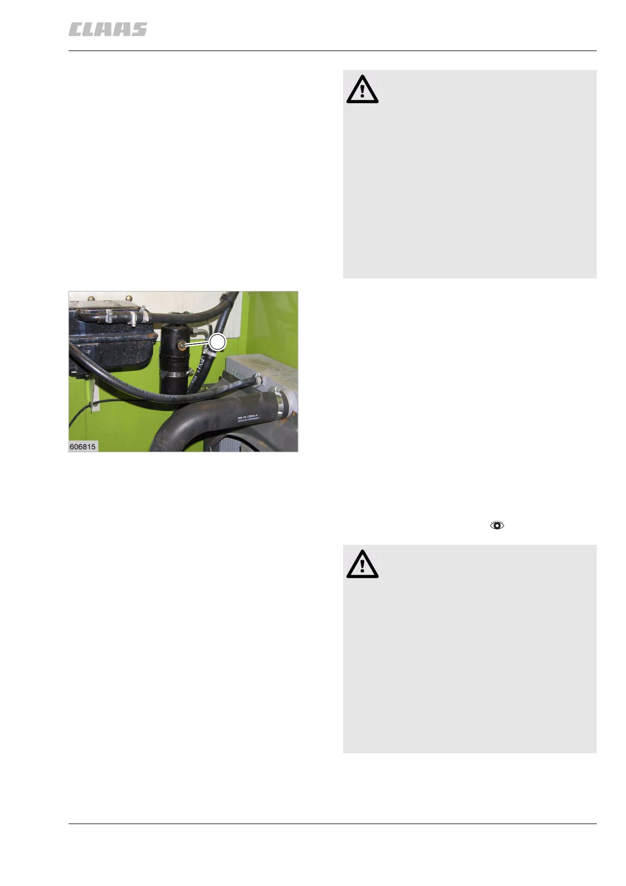
- Check the moisture saturation at the
receiver/dryer (1).
The moisture saturation of the receiver/dryer is
1
exceeded when the blue ball in the sight glass has
turned pink, or the orange ball has become colourless.
- If necessary, change refrigerant.
- If required, replace filter receiver drier (1).
128
23858
86839
13.11.7 Changing the air conditioner
refrigerant
- Observe the general warnings at the beginning of
the "Maintenance" chapter.
Danger!
Refrigerant.
Death or serious injury.
- Only have authorised and qualified work-
shops carry out work on air conditioning
systems.
- Never get in contact with refrigerants!
- Wear safety gloves and safety goggles.
- Do not weld any components of the refrig-
erant circuit and or in the immediate
vicinity of any parts of the refrigerant
circuit.
- Maximum ambient temperature for refrig-
erant is 80 °C.
351
13 Maintenance
13.11 Cab / Operator's platform
67089
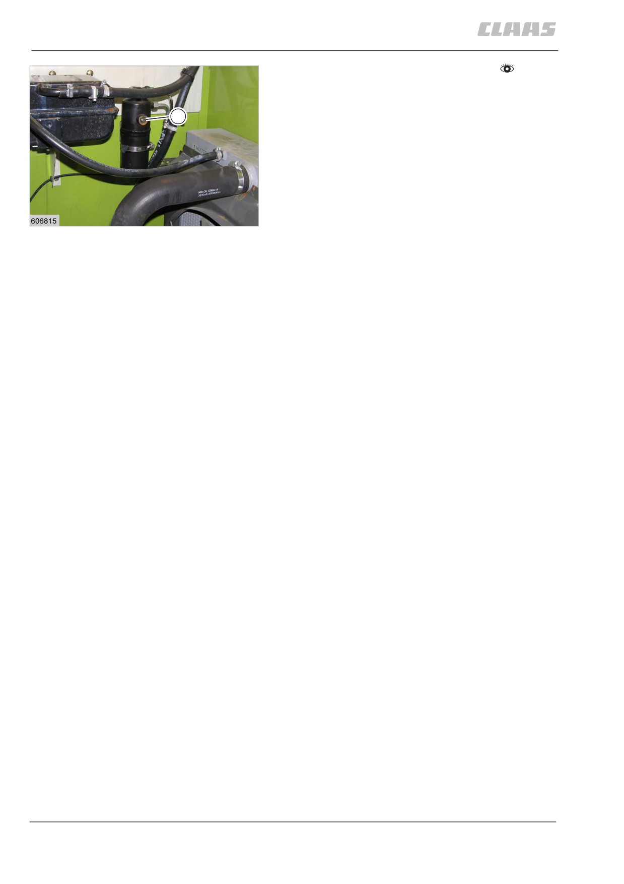
- Check refrigerant moisture saturation.
- Suction refrigerant.
- If required, replace filter receiver drier (1).
- Top up with specified quantity of refrigerant.
1
129
23858
352
13 Maintenance
13.12 Feeder unit
67089
13.12 Feeder unit
86866
13.12.1 Cleaning the feed rake conveyor
retainers
- Observe the general warnings at the beginning of
the "Maintenance" chapter.
Caution!
Machine operation with unpermitted or pol-
luted lubricants.
Machine damage.
- Ensure a clean environment.
- Use suitable and clean tools.
- Use permitted lubricants.
- Lubricants must be free of pollution.
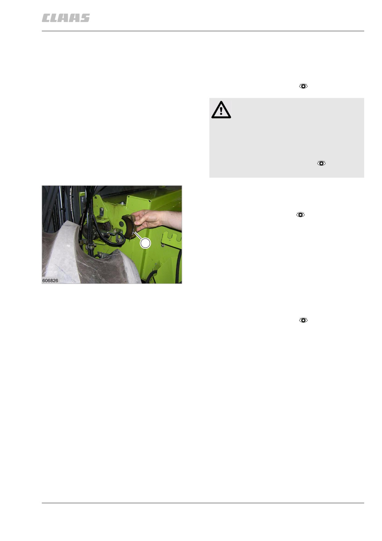
The bearing blocks (1) in the coupling forks of the feed
rake conveyor must be cleaned and graphite lubricant
must be applied.
- Remove front attachment.
- Support the feed rake conveyor at the front.
- Remove bearing block (1) on one side, clean it,
refit it with graphite lubricant and secure with a
1
pin.
- Repeat this procedure on the other side of the
machine.
130
23849
86872
13.12.2 Adjusting the feeder chains
- Observe the general warnings at the beginning of
the "Maintenance" chapter.
353
13 Maintenance
13.12 Feeder unit
67089
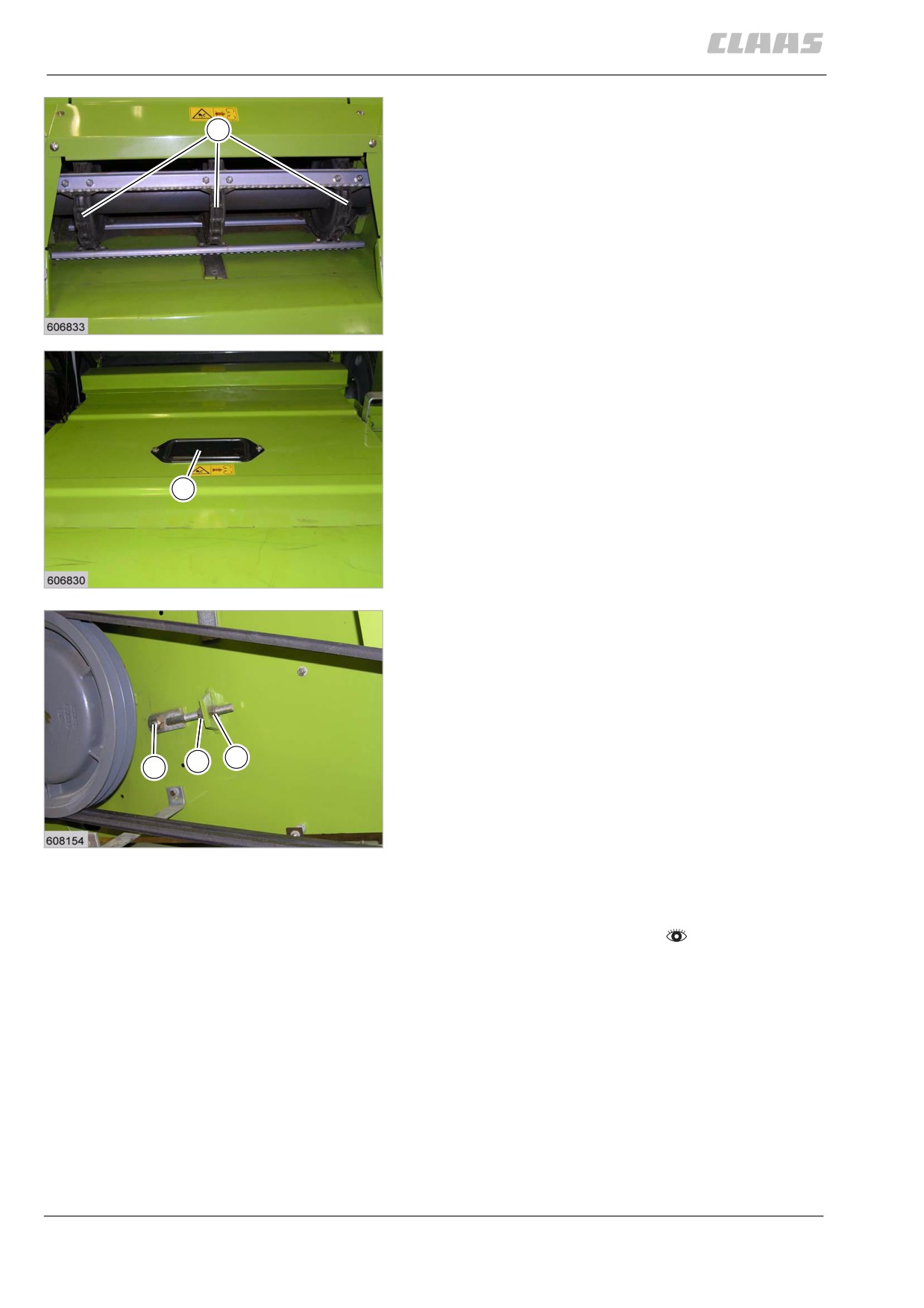
- Check the tension of the feeder chains (1) on the
feed rake conveyor through the flaps (2), with the
1
front attachment installed.
The feeder chains are correctly adjusted if the third
and fourth feeder bars from the front slightly touch the
ground.
- If necessary adjust the feeder chains.
131
23851
2
132
23852
- Adjust the feeder chains.
- Loosen nuts (1) and (3) on both sides.
- Adjust nut (2) until the chains on both sides are
uniformly tensioned.
- After tensioning, tighten the nuts (1) and (3) on
both sides.
- Close flaps.
1
2
3
133
23850
72926
13.12.3 Adjusting the feeder chain slip clutch
- Observe the general warnings at the beginning of
the "Maintenance" chapter.
354
13 Maintenance
13.12 Feeder unit
67089
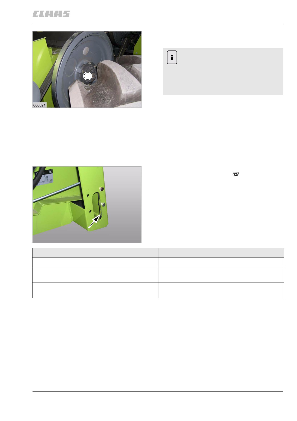
The slip clutch (1) protects the feeder chain against
overload.
Note!
Insufficient specialist knowledge for repair and
maintenance work.
1
Machine damage.
- Only have authorised and qualified work-
shops carry out work on this component.
- Never tighten the bolts to such an extent that the
134
slip clutch becomes locked and thereby fails to
19597
function as a safety device.
- Adjust the slip torque when the slip clutch is cold.
Slip torque = 220 Nm for springs with spacer tubes
Slip torque = 430 Nm with double springs
64786
13.12.4 Checking the rasp plates on the feed
rake conveyor
- Observe the general warnings at the beginning of
the "Maintenance" chapter.
The rasp plates wear due to the front attachment
movements.
- Check wear of rasp plates.
135
22082
Condition
Task
Rasp plate protrude around 1 mm at the rear.
- Check rasp plates in the next maintenance interval.
The rasp plates are flush with the feed rake conveyor
- Relocate rasp plates and use second hole pattern.
when installed in the first hole pattern.
The rasp plates are flush with the feed rake conveyor
- Install new rasp plates.
when installed in the second hole pattern.
355