CLAAS DOMINATOR 150 / 140 / 130. Operator’s Manual - page 21
13 Maintenance
13.8 Drive belts / drive chains
67089
87288
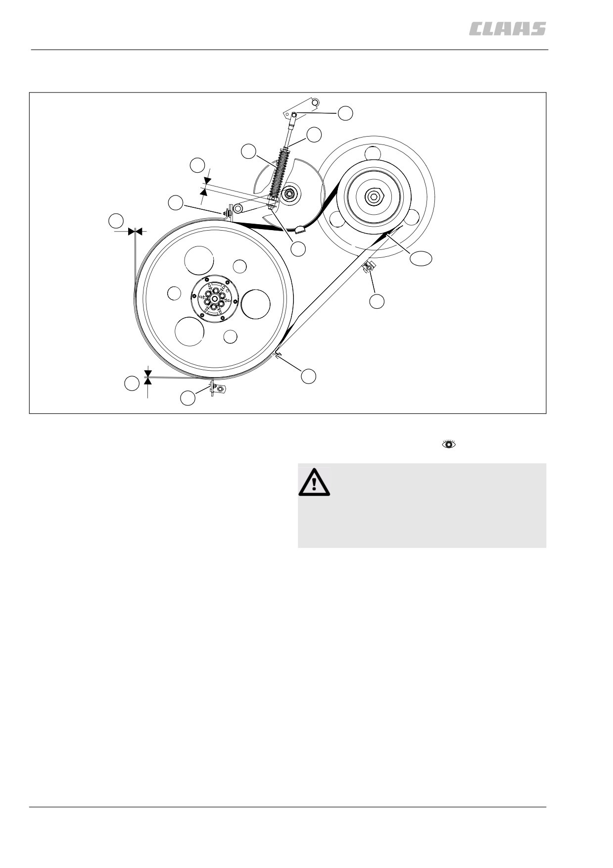
13.8.5 Adjusting belt (R2)
E
3
1
X
D
Z
2
R2
A
B
Y
C
29951
82
-
Observe the general warnings at the beginning of
the "Maintenance" chapter.
Danger!
Parts can be thrown off by a relaxing spring.
Serious injuries.
- Precisely follow the following handling
instructions.
-
Adjust the spring-loaded cylinder (1):
- Ensure that spring-loaded cylinder (1) is
mounted in the rear hole (E).
- Adjust spring guide tube (2) with the front
attachment engaged until
dimension (X) is around 20 mm. Adjust nut (3)
at the same time and jam with the spring guide
tube. Check dimension (X).
-
Adjusting the belt guide:
- Adjust belt guides at position (A, B, C and D) so
with the front attachment engaged that the fol-
lowing dimensions result between belt back
and belt guide.
Dimension (Y) = 5 - 7mm,
dimension (Z) = 4 mm
- Tighten all the bolts.
-
Carry out a test run and check belt tension.
324
13 Maintenance
13.8 Drive belts / drive chains
67089
87307
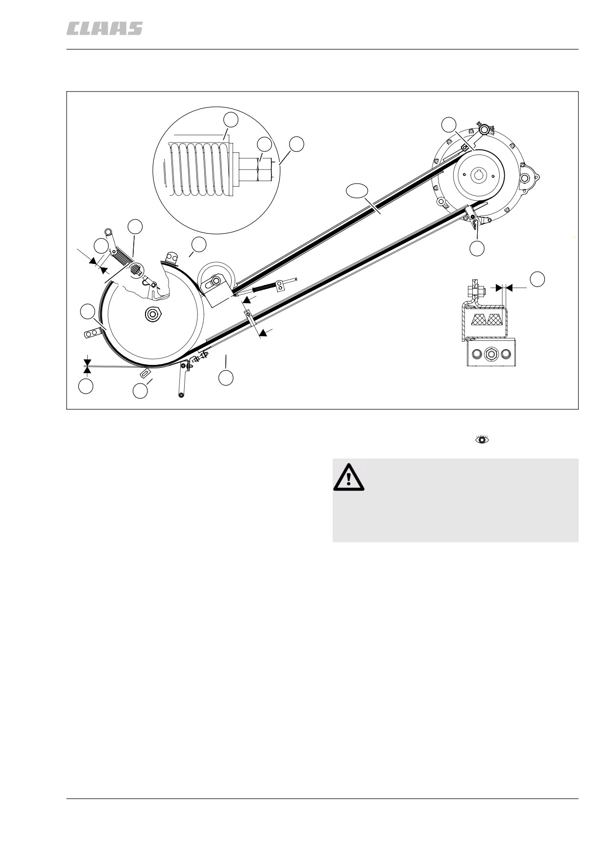
13.8.6 Adjusting belt (R3)
A
4
F
2
3
R3
1
X
E
A
A
Z
B-B
B
D
B
B
Y
C
30207
83
-
Observe the general warnings at the beginning of
the "Maintenance" chapter.
Danger!
Parts can be thrown off by a relaxing spring.
Serious injuries.
- Precisely follow the following handling
instructions.
-
Adjust the spring-loaded cylinder (1):
- Slacken off lock nut (3) with the threshing
mechanism engaged and turn the hex. head (2)
of spring guide tube until the indicator rod (4) is
flush with the end of the spring.
The dimension (X) = 20 mm results.
- Jam spring guide tube and jam nut (3).
-
Adjusting the belt guide:
- Adjust the belt guides at position (A, B, C, D, E
and F) so with the threshing mechanism
engaged that dimension (Y) = 5 mm results
on the entire circumference between belt
back and belt guide.
- Tighten all the bolts.
-
Carry out a test run and check belt tension.
325
13 Maintenance
13.8 Drive belts / drive chains
67089
87355
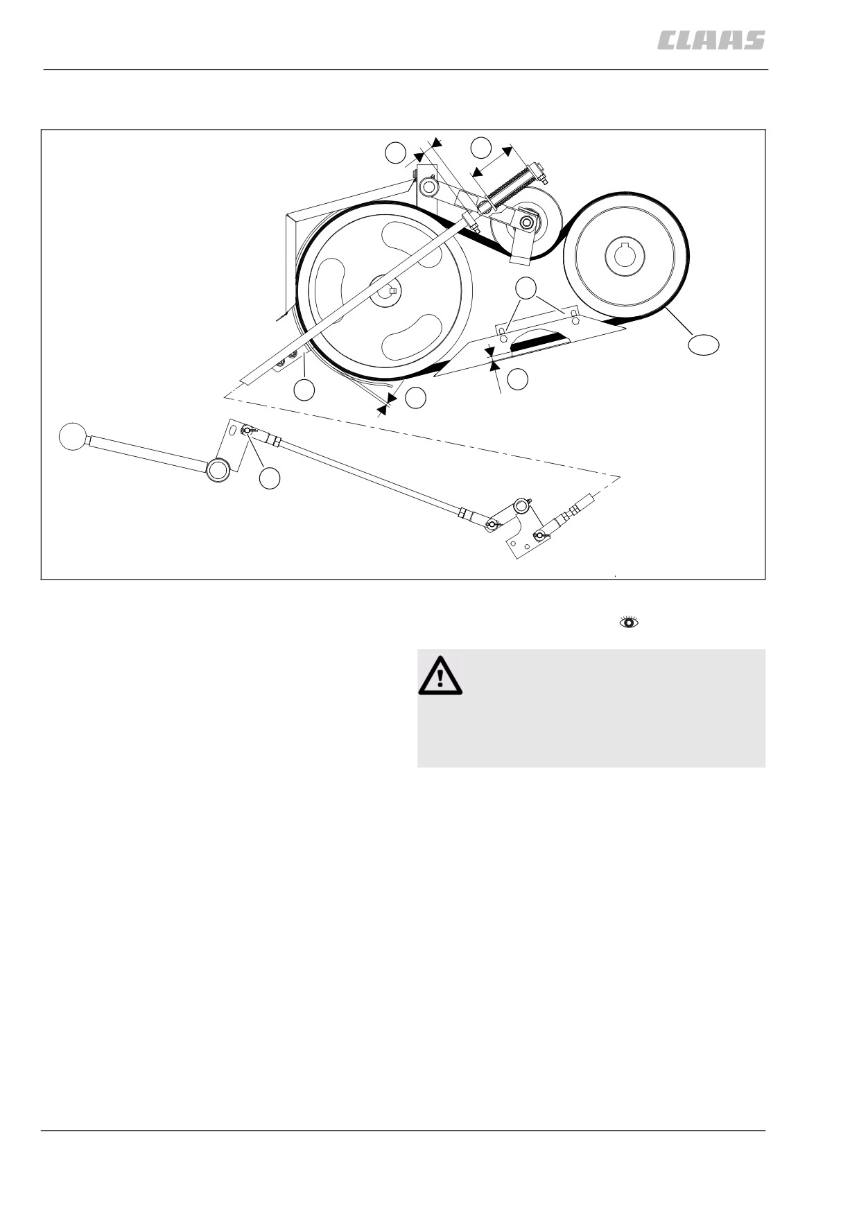
13.8.7 Adjusting belt (R4)
X
Y
B
R4
Z
A
W
C
29977
84
-
Observe the general warnings at the beginning of
the "Maintenance" chapter.
Danger!
Parts can be thrown off by a relaxing spring.
Serious injuries.
- Precisely follow the following handling
instructions.
-
Ensure that the linkage is mounted in the bottom
hole (C).
-
Adjust the spring-loaded cylinder (1):
- Adjust the set collar (2) so with the grain tank
unloading engaged that the spring
length (X) is 100 mm.
- Now adjust set collar (1) so with the grain tank
unloading engaged that the
dimension (Y) is 20 mm.
-
Adjusting the belt guide:
- Adjust belt guides at position (A and B) so with
the grain tank unloading engaged that the fol-
lowing dimensions result between belt back
and belt guide.
Dimension (W) = 5 mm on the entire circum-
ference, dimension (Z) = 7 mm
- Tighten all the bolts.
326
13 Maintenance
13.8 Drive belts / drive chains
67089
- Carry out a test run and check belt tension.
87394
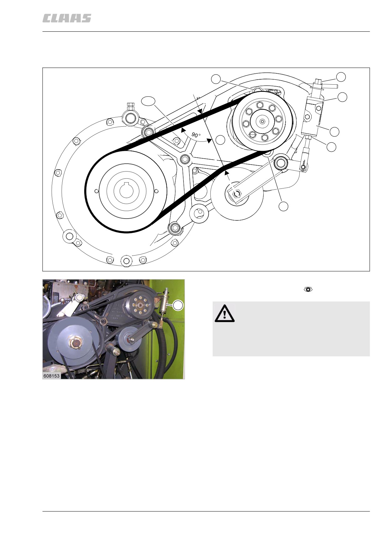
13.8.8 Adjusting belt (R5)
1
3
4
R5
6
X
2
3
29986
85
- Observe the general warnings at the beginning of
the "Maintenance" chapter.
6
Warning!
Pinch points during assembly work.
Bruises of limbs.
- Keep limbs out of the hazard area.
- Use suitable tools.
- Slacken off nut (2) until tube (6) has a little play
from bracket (4).
86
23840
- Check dimension (X) = 187+10 mm .
- Slacken off bolts (3) if required and relocate
hydraulic pump until dimension (Y) has been
reached. Ensure that tube (6) always has some
play from bracket (4) while relocating.
- Tighten bolts (3).
- Jam spring guide tube (1) and nut (2). Ensure that
tube (6) makes contact with bracket (4) without
play.
- Carry out a test run and check belt tension.
327
13 Maintenance
13.8 Drive belts / drive chains
67089
87583
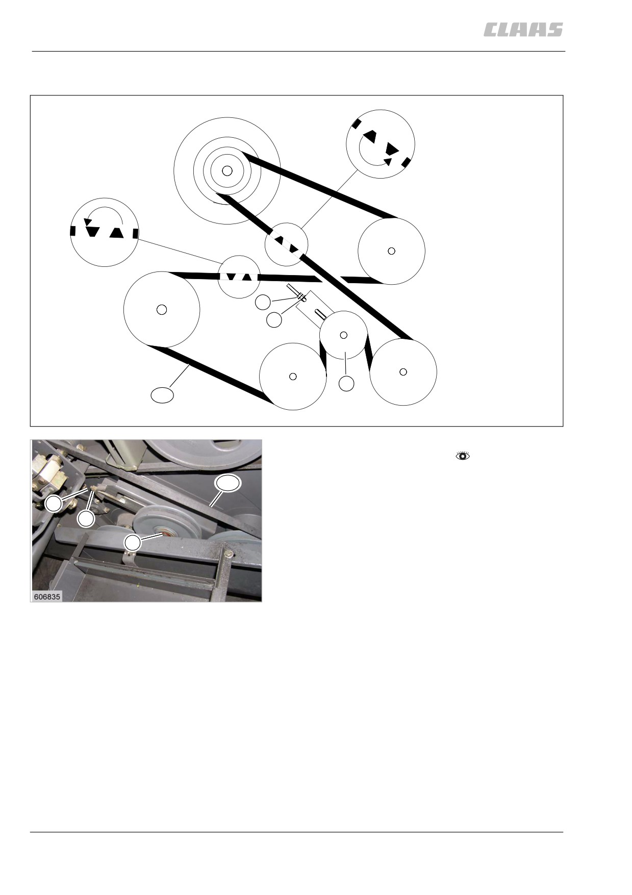
13.8.9 Adjusting belt (R8)
180°
180°
3
2
1
R8
30031
87
- Observe the general warnings at the beginning of
the "Maintenance" chapter.
- Loosen the clamping screw of the jockey
R8
pulley (1).
- Turn nuts (2) and (3) until belt (R10) is tensioned.
3
- Lock nuts (2) and (3).
2
- Tighten the clamping screw of the jockey
1
pulley (1).
- Tightening torque = 130 Nm
- Carry out a test run and check belt tension.
88
23842
328
13 Maintenance
13.8 Drive belts / drive chains
67089
87600
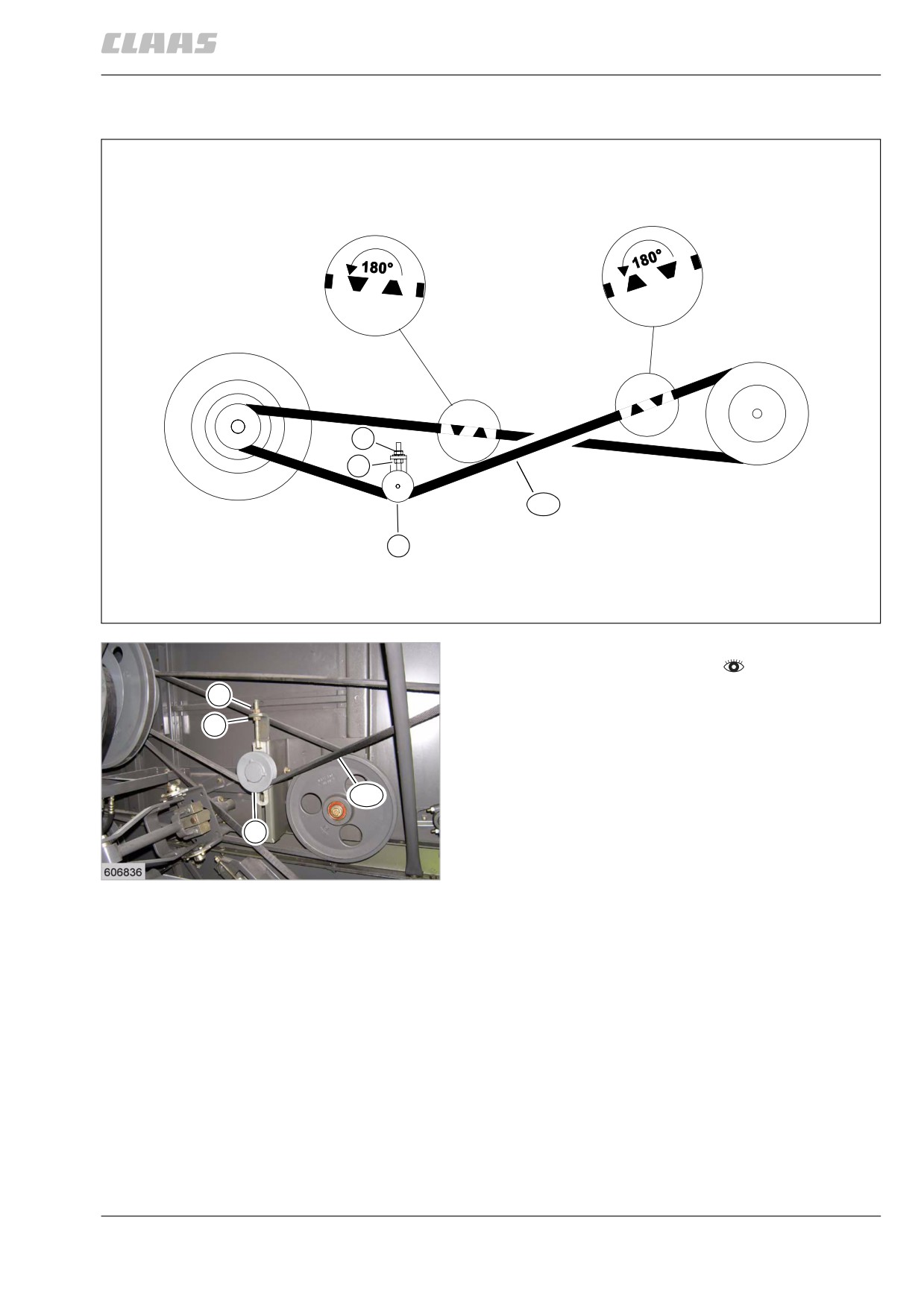
13.8.10 Adjusting belt (R9)
3
2
R9
1
30039
89
- Observe the general warnings at the beginning of
the "Maintenance" chapter.
- Loosen the clamping screw of the jockey
3
pulley (1).
2
- Turn nuts (2) and (3) until belt (R10) is tensioned.
- Lock nuts (2) and (3).
- Tighten the clamping screw of the jockey
pulley (1).
R9
- Tightening torque = 40 Nm
1
- Carry out a test run and check belt tension.
90
23841
329
13 Maintenance
13.8 Drive belts / drive chains
67089
87418
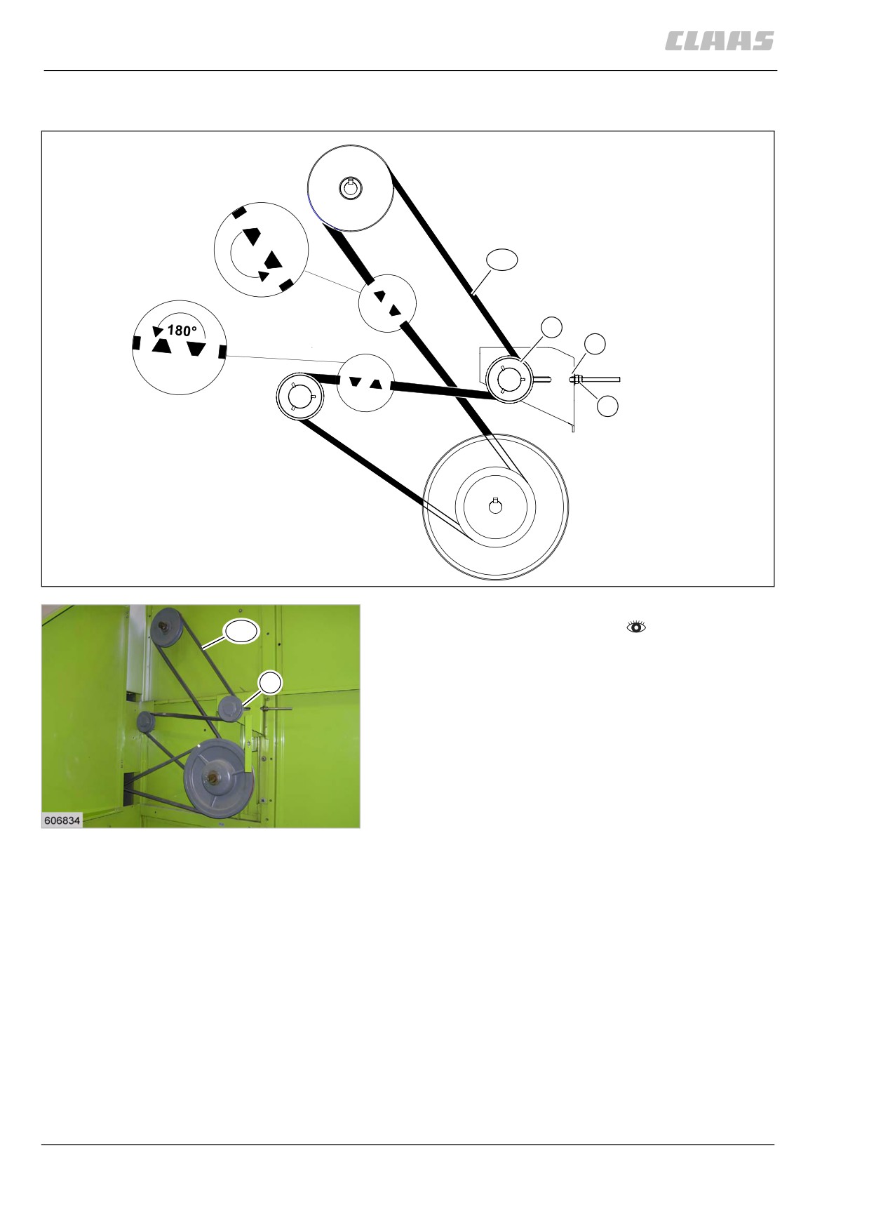
13.8.11 Adjusting belt (R10)
180°
R10
1
2
3
30029
91
- Observe the general warnings at the beginning of
the "Maintenance" chapter.
R10
- Loosen the clamping screw of the jockey
pulley (1).
1
- Turn nuts (2) and (3) until belt (R10) is tensioned.
- Lock nuts (2) and (3).
- Tighten the clamping screw of the jockey
pulley (1).
- Tightening torque = 40 Nm
- Carry out a test run and check belt tension.
92
23843
330
13 Maintenance
13.8 Drive belts / drive chains
67089
87615
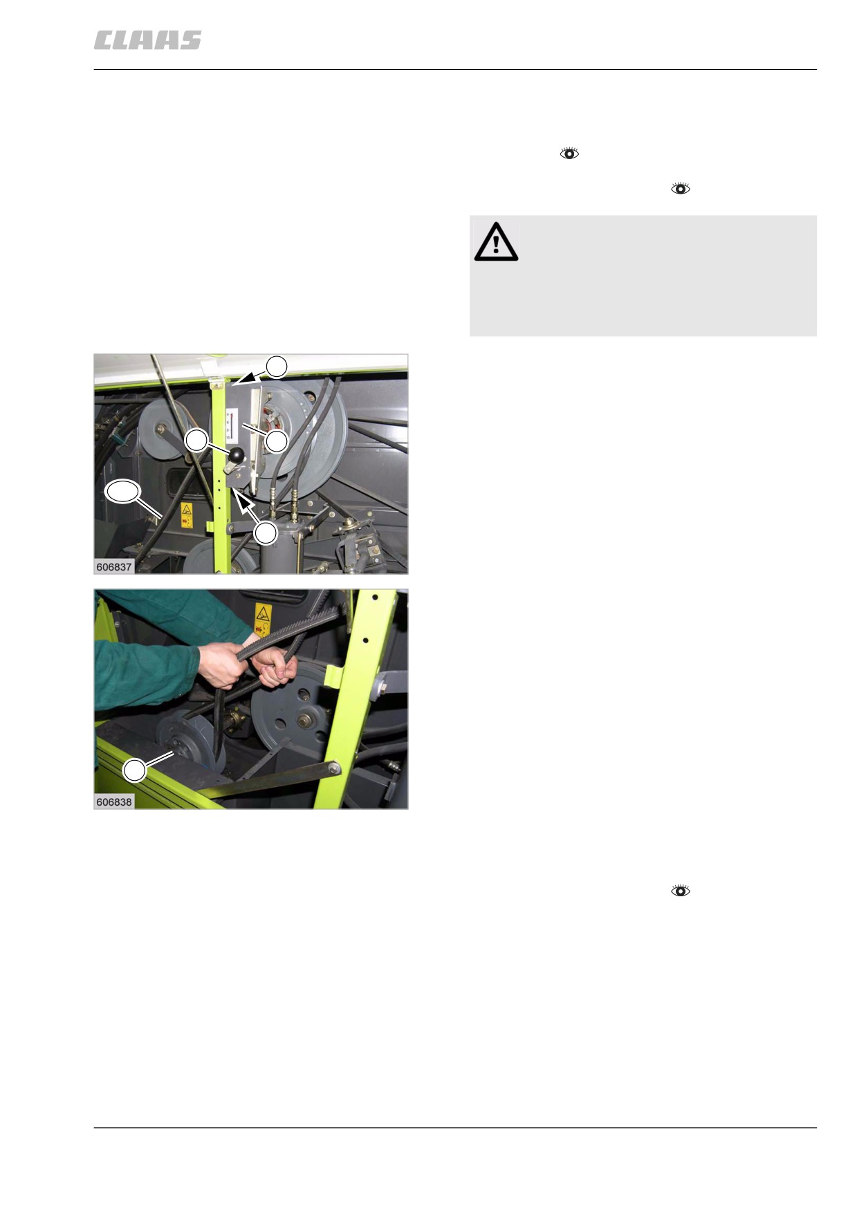
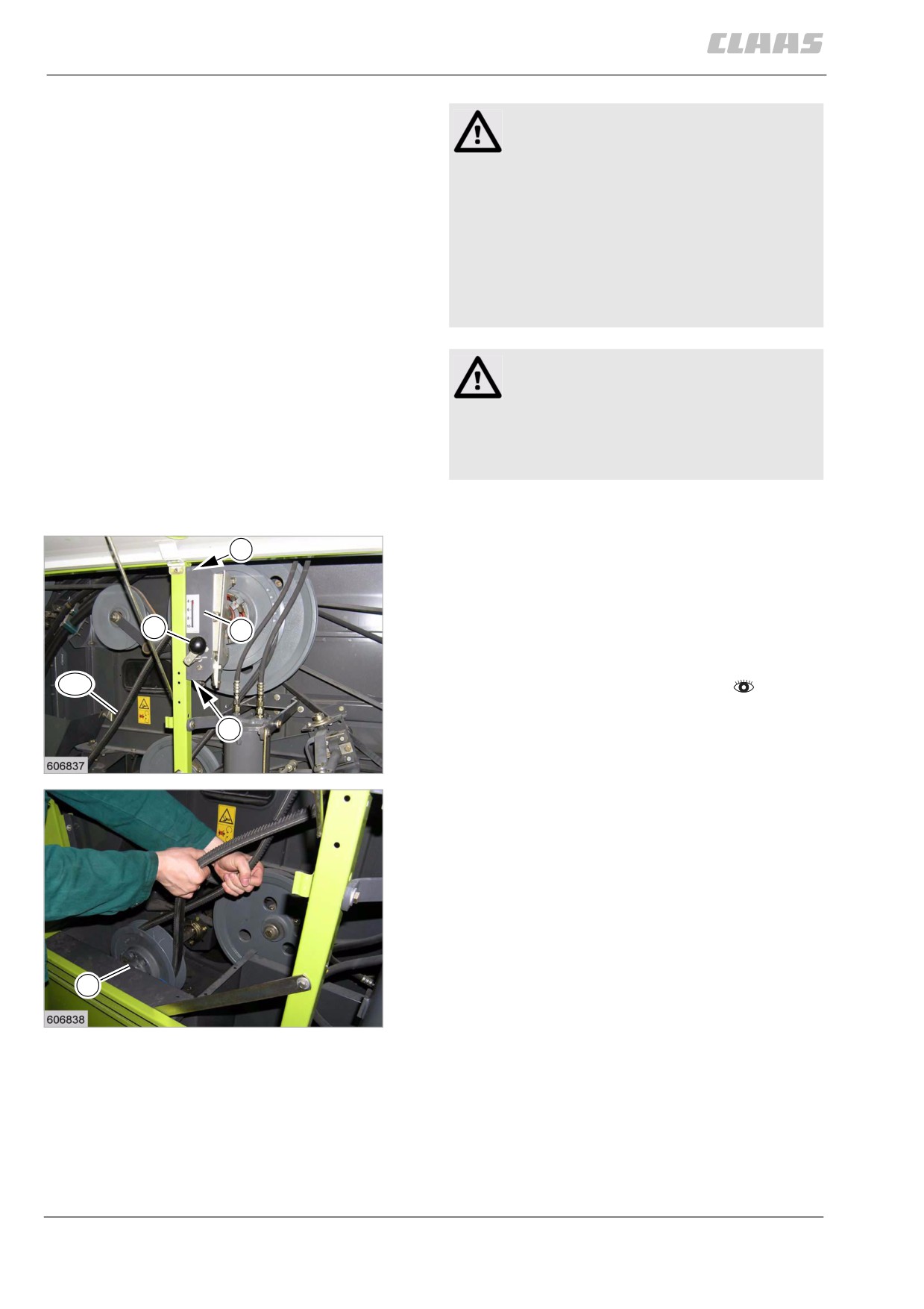
13.8.12 Removing belt (R7)
-
Set fan speed to the highest value with
crank (1).
-
Observe the general warnings at the beginning of
the "Maintenance" chapter.
Warning!
Pinch points during assembly work.
Bruises of limbs.
- Keep limbs out of the hazard area.
- Use suitable tools.
-
Unscrew two bolts (4) from bracket (3).
4
–
Tension the belt (R7) manually until the spring-
loaded variable-speed pulley (2) is fully spread.
-
Remove belt (R7).
1
3
R7
4
93
23404
2
94
23405
87616
13.8.13 Installing belt (R7)
- Observe the general warnings at the beginning of
the "Maintenance" chapter.
331
13 Maintenance
13.8 Drive belts / drive chains
67089
WARNING:
Use of unpermissible spare parts or
lubricants.
Machine damage or increased wear.
- Spare parts and lubricants must at least
comply with the technical standards
required by the manufacturer of the
implement!
- The use of genuine CLAAS spare parts
and lubricants is recommended.
Warning!
Pinch points during assembly work.
Bruises of limbs.
- Keep limbs out of the hazard area.
- Use suitable tools.
-
Clean the grooves or the contact faces of pulleys
to be free from grease and rust.
-
First put the belt (R7) on the spring-loaded varia-
4
ble speed pulley (2).
-
Pull the belt into the variable-speed pulley (2) until
it is fully spread.
-
Install belt (R7) on the upper variable-speed
1
3
pulley.
-
Bolt down bracket (3) with bolts (4).
R7
-
Check / adjust the fan speed display.
–
Let the variable-speed drive run up and down
4
through its entire range several times, then check
belt tension.
95
23404
2
96
23405
332
13 Maintenance
13.8 Drive belts / drive chains
67089
87662
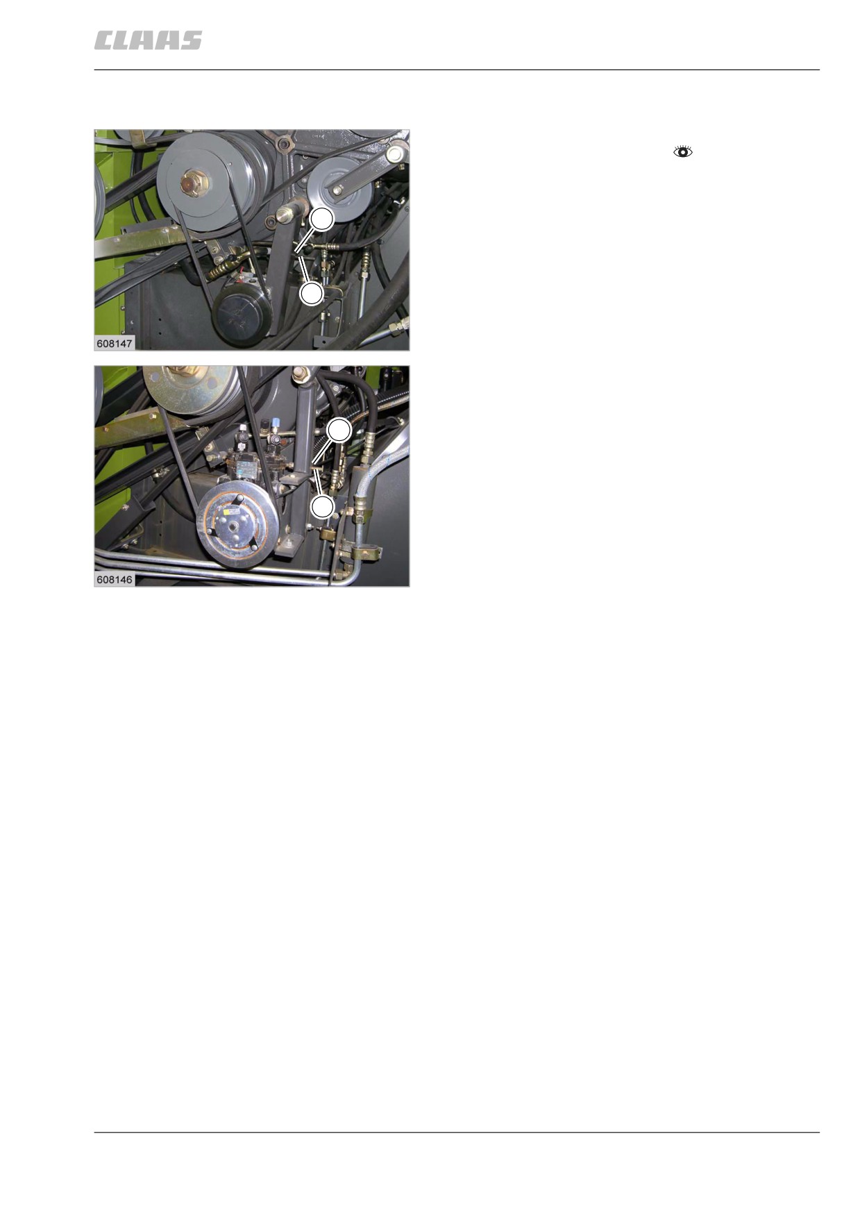
13.8.14 Adjusting belt (R12)
- Observe the general warnings at the beginning of
the "Maintenance" chapter.
- Turn nuts (2) and (3) until belt (R12) is tensioned.
- Lock nuts (2) and (3).
- Carry out a test run and check belt tension.
2
3
97
Sanden compressor
19303
2
3
98
York compressor
19297
333
13 Maintenance
13.8 Drive belts / drive chains
67089
87669
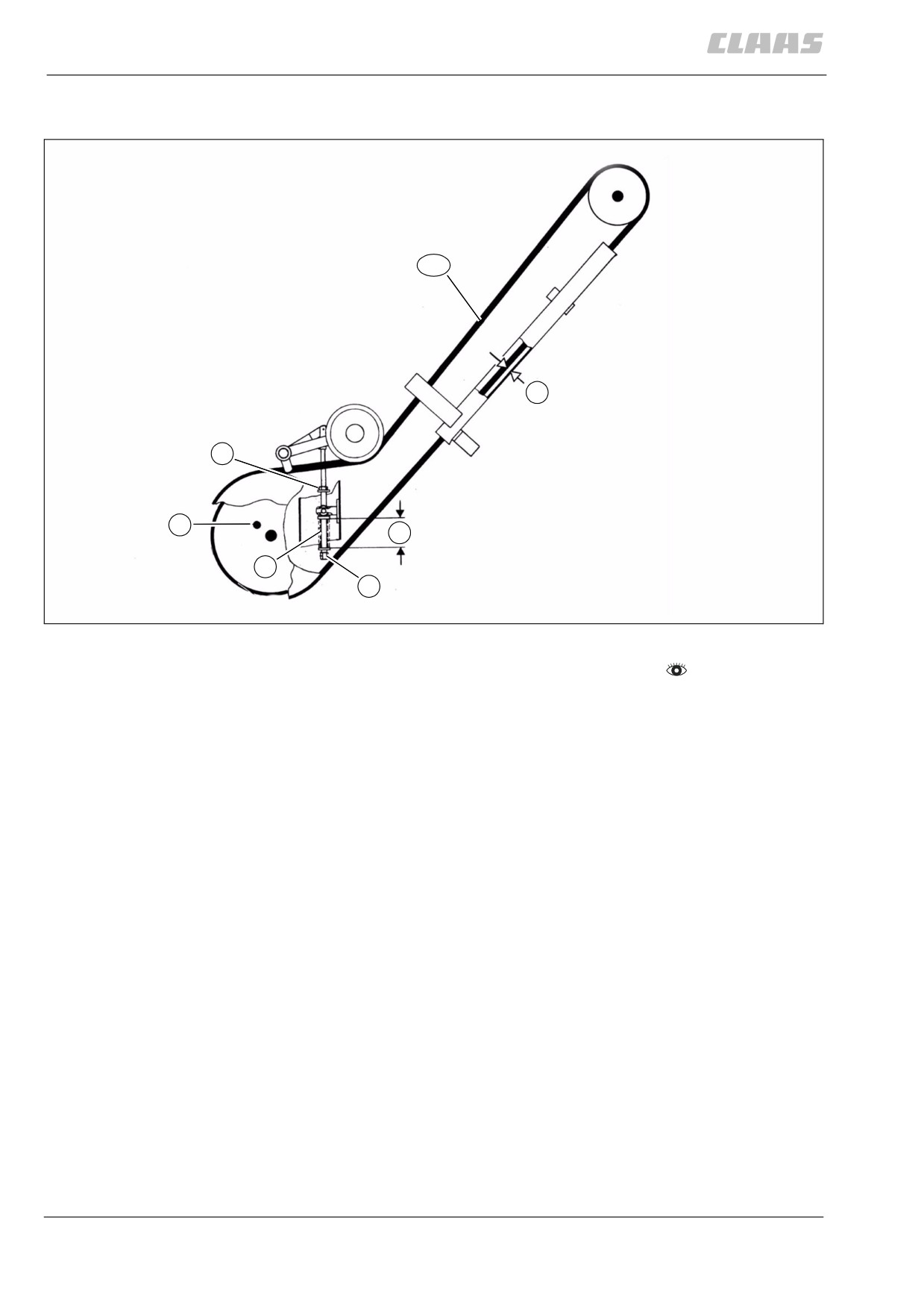
13.8.15 Adjusting belt (R13)
R13
Y
1
4
Z
3
2
30057
99
- Observe the general warnings at the beginning of
the "Maintenance" chapter.
Adjust the spring-loaded cylinder (3):
- Loosen lock nut (1). Adjust spring guide tube (2)
so that spring (3) is slightly coil-bound. Then turn
the spring guide tube 2 mm back. The spring must
then have a length (Z) of approx. 87 mm.
Adjusting the belt guide:
- Adjust the guide so that there is 13 mm clearance
(Y) between the back of the belt and the belt guide
along its full length.
- Carry out a test run and check belt tension.
334
13 Maintenance
13.8 Drive belts / drive chains
67089
87674
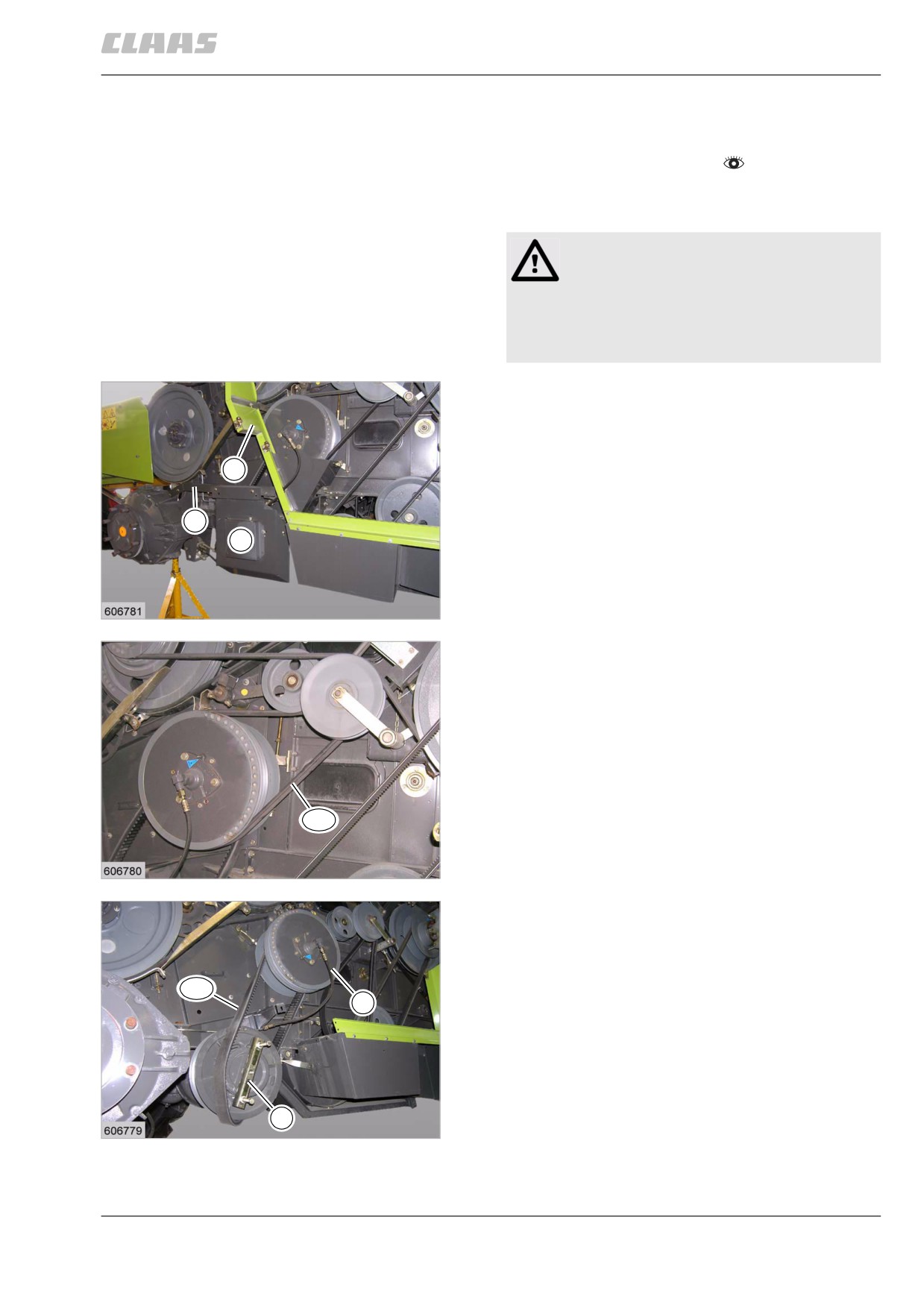
13.8.16 Removing belt (R14)
- Observe the general warnings at the beginning of
the "Maintenance" chapter.
- Operate the variable-speed drive to the full speed
position while the engine is running.
Warning!
Pinch points during assembly work.
Bruises of limbs.
- Keep limbs out of the hazard area.
- Use suitable tools.
- Securely support the machine on the left-hand
side. Remove the left-hand traction wheel.
- Remove guards (1 and 2) as well as angle iron
(3).
2
3
1
100
23402
- Remove belt (R13).
R13
101
23401
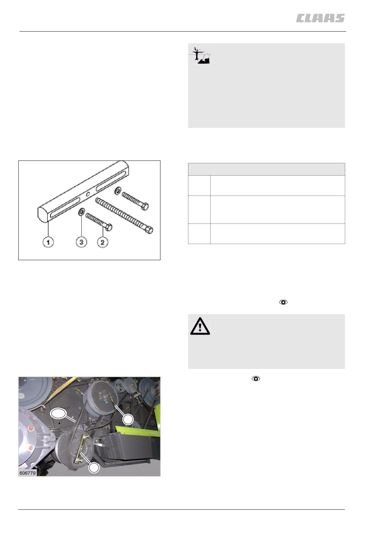
- Screw special tool (4) on the variable-speed
pulley.
- Push the lever on the hydraulic control unit to the
"slow" position and at the same time push the
hydraulically operated variable-speed pulley
R14
5
halves apart.
4
102
23403
335
13 Maintenance
13.8 Drive belts / drive chains
67089
Environment!
Lubricants and fuels end up in the
environment.
Environmental pollution.
- Lubricants and fuels must be collected
and stored in suitable containers and dis-
posed of in a way that is harmless to the
environment and in accordance with
existing anti-pollution regulations.
- Unscrew the hydraulic hose from hydraulic cylin-
der (5).
- Remove belt (R14).
Special tool 5
1
Puller bridge
Part no. 00 0181 621 0
2
Hex. bolt
M 12 x 200 ISO 40172 - 8.8
Part no. 00 0244 421 0
3
Washer 13 x 30 x 3
Part no. 00 0236 844 0
103
567
87716
13.8.17 Installing belt (R14)
- Observe the general warnings at the beginning of
the "Maintenance" chapter.
Warning!
Pinch points during assembly work.
Bruises of limbs.
- Keep limbs out of the hazard area.
- Use suitable tools.
- Adjust belt (R14).
- Install belt (R14).
- Remove special tool (4).
- Install belt (R13).
R14
- Screw on hydraulic hose (5).
5
4
104
23403
336
13 Maintenance
13.8 Drive belts / drive chains
67089
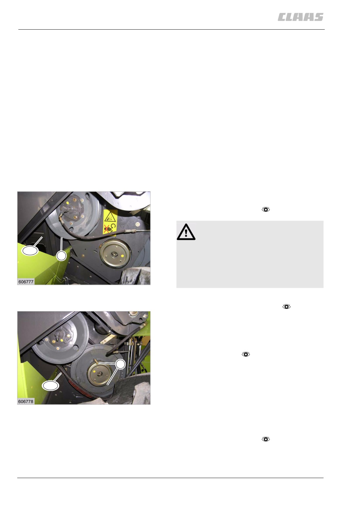
- Fit guards (1 and 2) and angle iron (3).
- Install drive wheel on the left machine side.
2
R13
3
1
105
23402
87717
13.8.18 Adjusting belt (R14)
4
R14
6
x
5
30056
106
- Observe the general warnings at the beginning of
the "Maintenance" chapter.
Warning!
Pinch points during assembly work.
Bruises of limbs.
- Keep limbs out of the hazard area.
- Use suitable tools.
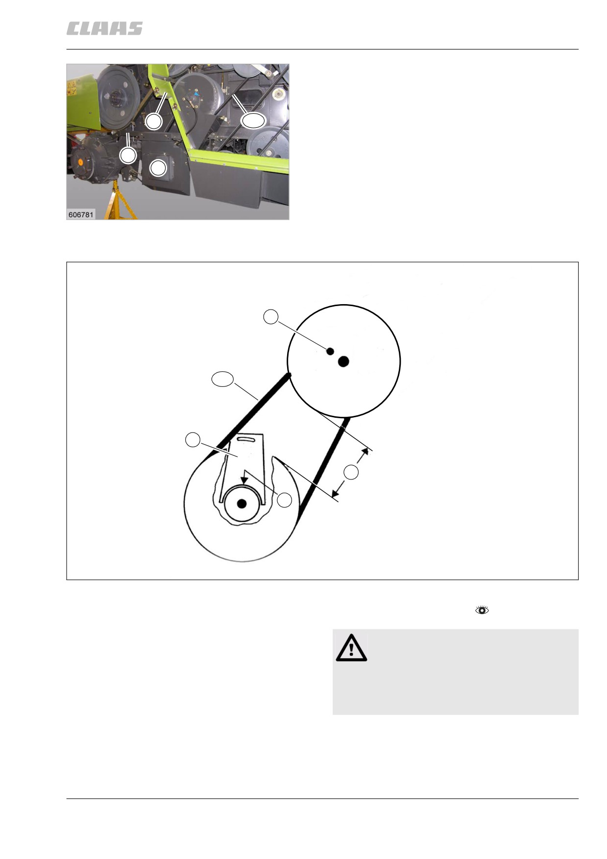
Setting the ground drive variable-speed pulleys:
- The distance (X) between the variable-speed pul-
leys must be 280 mm.
337
13 Maintenance
13.8 Drive belts / drive chains
67089
- Force the spring-loaded ground drive variable-
speed pulley apart, using a special tool.
- Slacken the bolts that secure the gearbox hous-
ing. Adjust the gearbox housing up or down until
measurement (X) has been obtained (provision for
adjustment ± 3 mm). Retighten the bolts that
secure the gearbox housing.
- Loosen support plate (6). Push down the plate to
locate tightly against the transmission neck at (5),
then tighten the bolts that secure the plate.
- Remove the special tool.
- Whenever the settings have been adjusted, make
a functional test, check for proper adjustments
and correct as required.
Note: The stop bolt (4) serves for limiting the maximum
ground speed according to the German Regulations
Authorizing the Use of Vehicles for Road Traffic.
87272
13.8.19 Removing belt (R42)
-
Set variable speed drive to lowest speed.
–
Observe the general warnings at the beginning of
the "Maintenance" chapter.
Danger!
Pinch points due to pre-loaded components.
Consequences: Death or serious injuries
R41
1
- Never move your hands between two pre-
loaded components.
- Use a special tool.
107
- Avoid the hazard area.
23399
-
Remove guards.
–
Remove belt (R41) from pulley (1).
–
Screw in special tool (2, part no. 00 0236 302 0,
2 pcs.) through the tapped holes of the front pulley
half.
-
Screw in bolts (2) until the variable-speed drive is
completely spread apart.
-
Remove belt (R42).
2
R42
108
23400
87276
13.8.20 Installing belt (R42)
- Observe the general warnings at the beginning of
the "Maintenance" chapter.
338
13 Maintenance
13.8 Drive belts / drive chains
67089
WARNING:
Use of unpermissible spare parts or
lubricants.
Machine damage or increased wear.
- Spare parts and lubricants must at least
comply with the technical standards
required by the manufacturer of the
implement!
- The use of genuine CLAAS spare parts
and lubricants is recommended.
Danger!
Pinch points due to pre-loaded components.
Consequences: Death or serious injuries
- Never move your hands between two pre-
loaded components.
- Use a special tool.
- Avoid the hazard area.
-
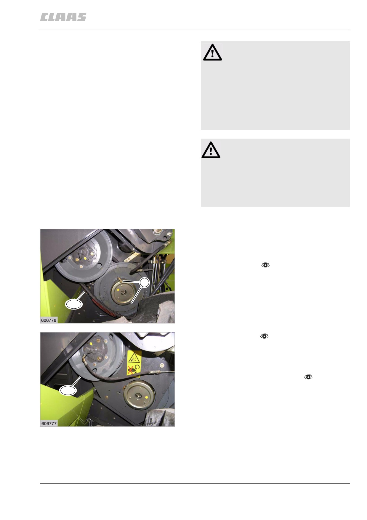
Clean the grooves or the contact faces of pulleys
to be free from grease and rust.
-
Pull belt (R42) firmly between the pulley halves
and unscrew the bolts (1).
-
Continue turning the variable speed drive about
2 revolutions.
-
Adjust belt (R42).
1
R42
109
23400
-
Install belt (R41).
–
Fit the guards.
–
Let the variable-speed drive run up and down
through its entire range several times, then check
belt tension.
-
Adjust the threshing drum speed.
R41
110
23399
339