CLAAS DOMINATOR 150 / 140 / 130. Operator’s Manual - page 23
13 Maintenance
13.13 Threshing mechanism
67089
13.13 Threshing mechanism
82170
13.13.1 Cleaning the stone trap
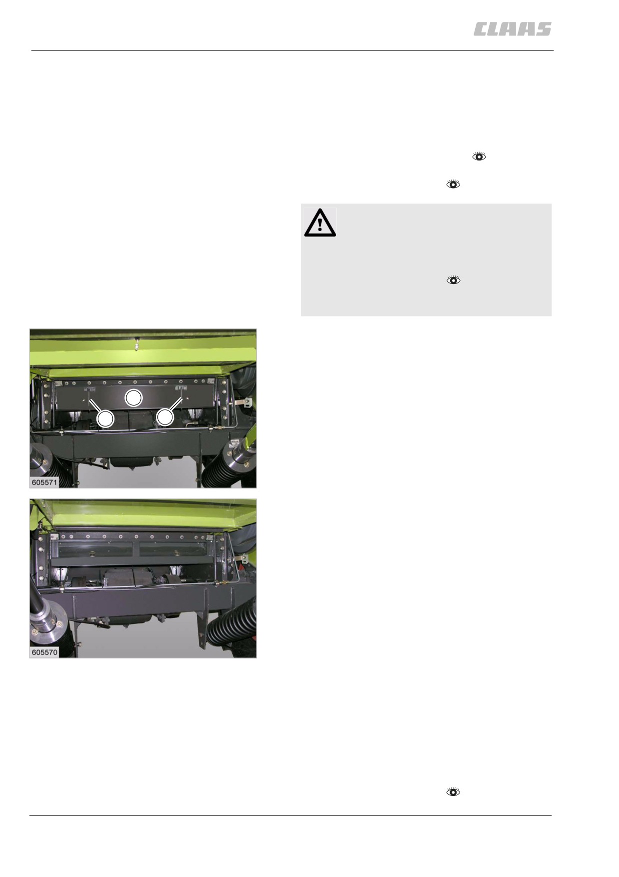
The stone trap collects stones and other foreign
objects up to a certain size and thus protects the
threshing mechanism against damage.
- Raise the feeder unit all the way.
- Observe the general warnings at the beginning of
the "Maintenance" chapter.
Danger!
The front attachment, reel and feeder unit may
drop uncontrolled.
Death or serious injuries!
- Apply safety locks.
- Keep a safe distance from the hazard
area.
- Open the latch (1) and remove the flap (2).
- Clean the stone trap.
- Install the flap and close the latch.
2
1
1
136
19603
137
19604
82233
13.13.2 Cleaning the threshing mechanism
Especially when working in green and damp crops, the
concave, the threshing drum and the preparation floor
can quickly become clogged with dirt.
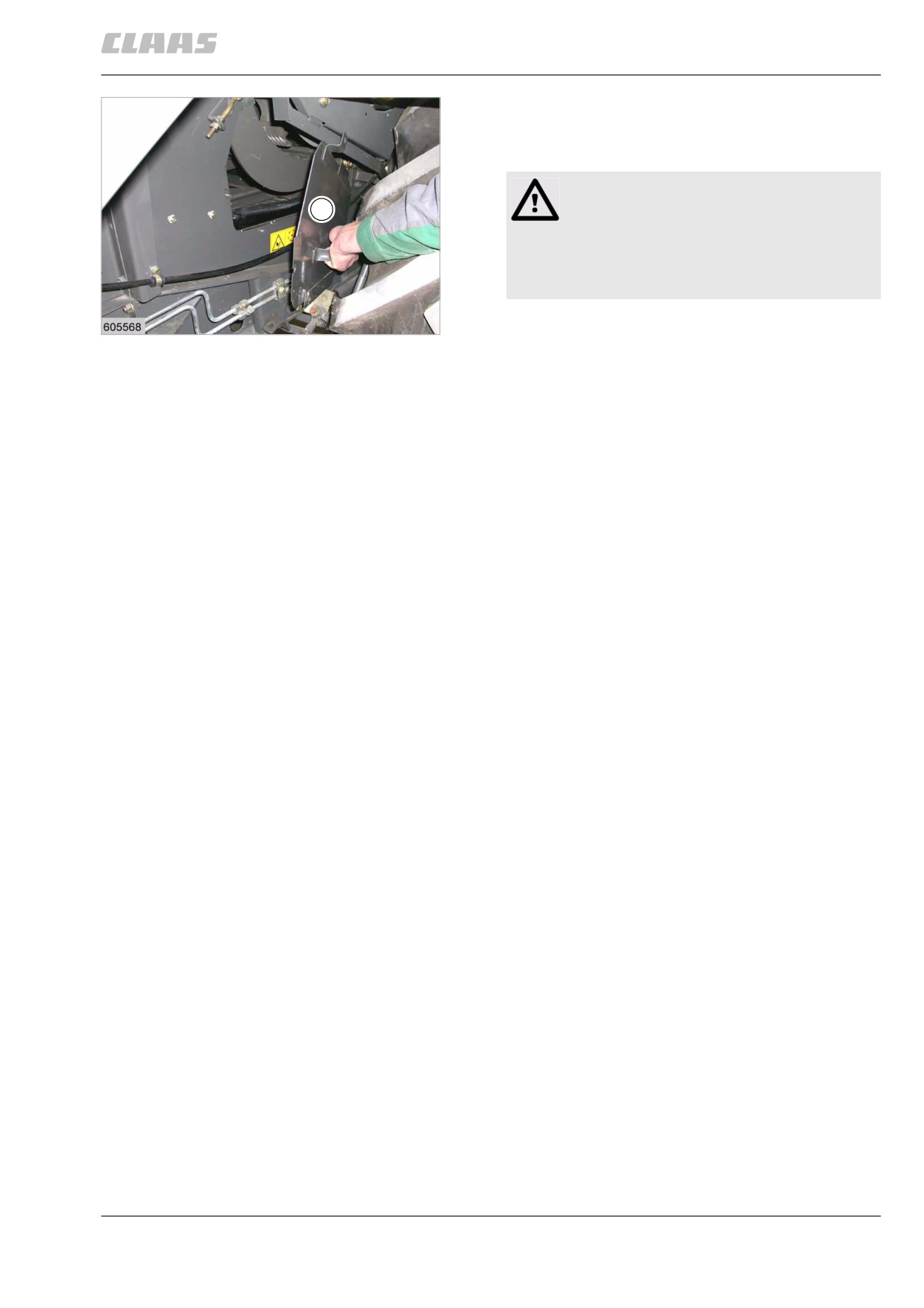
A large inspection hole facilitates inspection and clean-
ing after the flap (1) is removed.
- Observe the general warnings at the beginning of
the "Maintenance" chapter.
356
13 Maintenance
13.13 Threshing mechanism
67089
- Open cover (1).
- Clean the threshing concave, threshing drum and
preparation floor.
WARNING:
1
Unbalance of the threshing drum.
Machine damage.
- Uniformly clean the rasp bars and cover
plates from the inside.
- Uniformly clean the rasp bars and cover plates
138
19609
from the inside.
- Close flap (1).
357
13 Maintenance
13.14 Separation
67089
13.14 Separation
82474
13.14.1 Cleaning the straw walker
- Observe the general warnings at the beginning of
the "Maintenance" chapter.
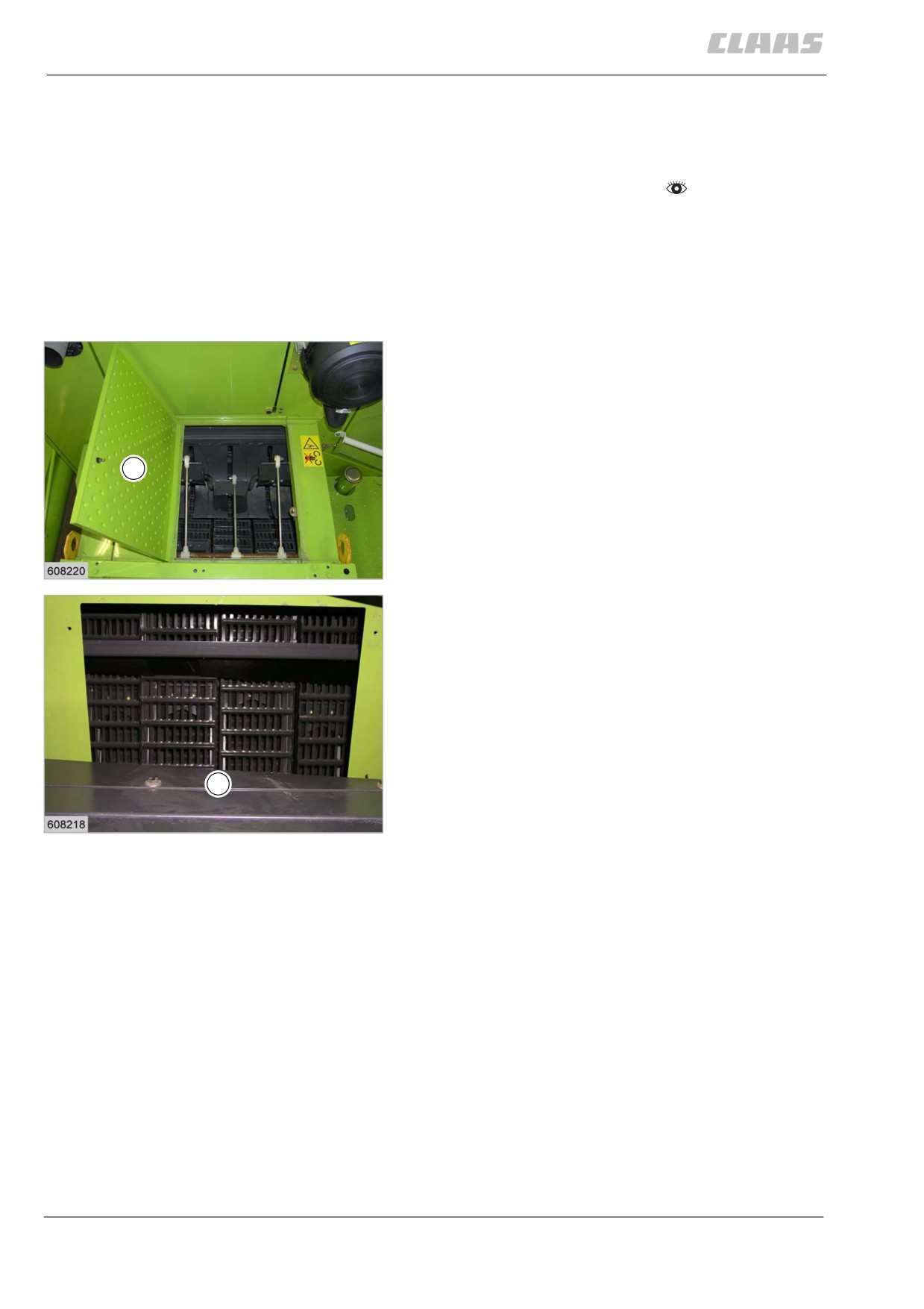
The straw walkers must be checked / cleaned when
working with moist straw and straw with a high weed
content. If necessary, remove dirt with an aid.
The straw walker house can be accessed through a
flap (1) on the machine roof and through a flap (2) in
the grain tank.
- Open flap.
- If necessary, remove dirt with an aid.
1
139
19626
2
140
19630
358
13 Maintenance
13.14 Separation
67089
82458
13.14.2 Checking the deflector curtain
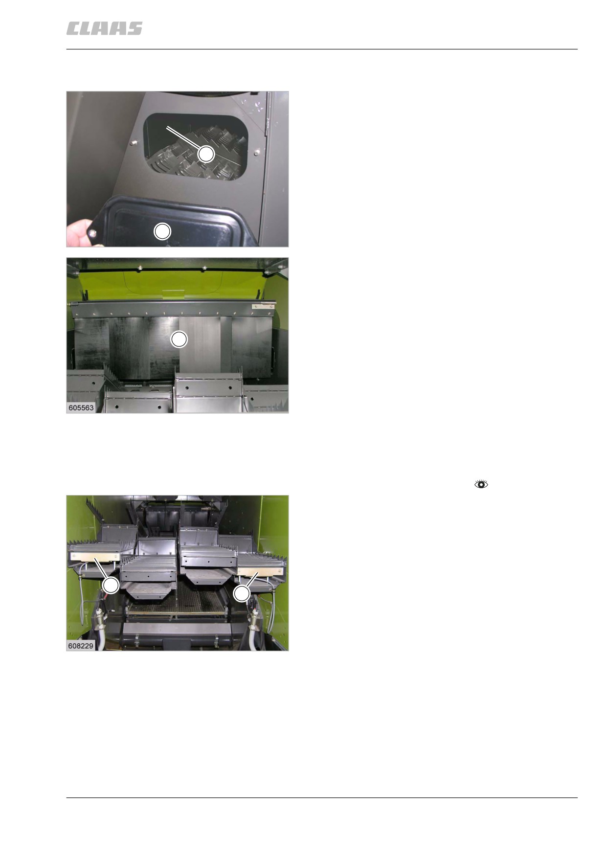
A height-adjustable deflector curtain (1) located behind
the impeller collects even the last deflected bouncing
grains and directs them onto the front of the straw
walker.
A worn or excessively high deflector curtain will cause
1
the bouncing grains to be thrown too far to the rear of
the straw walker and not be separated in time any
more.
The deflector curtain (1) can be seen through the
flaps (2) on the left and right side of the machine.
2
- Check flawless condition of deflector curtain and
141
replace it if necessary.
28513
1
142
19623
82752
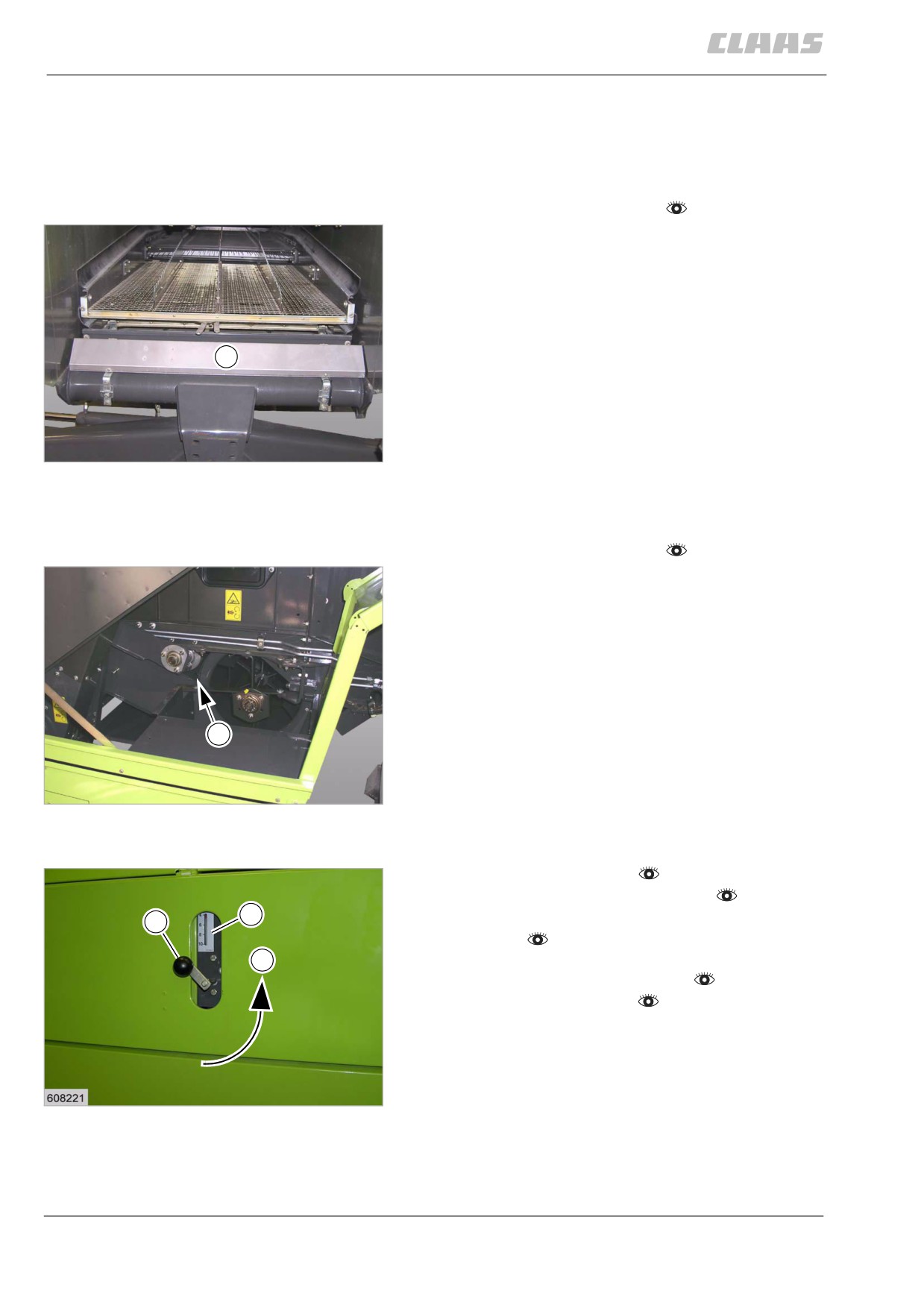
13.14.3 Cleaning the separation throughput
monitor sensor
- Observe the general warnings at the beginning of
the "Maintenance" chapter.
- Clean sensor (1).
1
1
143
19647
359
13 Maintenance
13.15 Cleaning unit
67089
13.15 Cleaning unit
82760
13.15.1 Cleaning the cleaning throughput
monitor sensor
- Observe the general warnings at the beginning of
the "Maintenance" chapter.
- Clean sensor (1).
1
144
19648
82772
13.15.2 Cleaning the fan
- Observe the general warnings at the beginning of
the "Maintenance" chapter.
- Clean the space (A) above the fan.
A
145
28594
82923
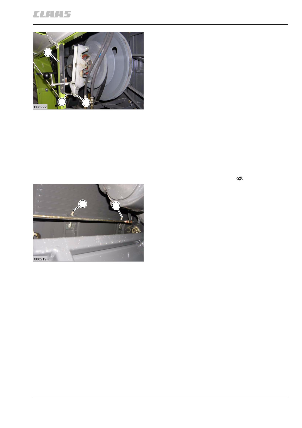
13.15.3 Setting the fan speed gauge
- Start the diesel engine.
- Engage the threshing mechanism.
2
- Set the diesel engine speed to fast idling
1
speed.
-
- Set fan speed to the lowest value with crank (1).
- Stop the threshing mechanism.
- Stop the diesel engine.
146
19634
360
13 Maintenance
13.15 Cleaning unit
67089
- Open the side panel.
- Loosen clamp (4) and adjust plastic indicator rod
(3) so that the coloured ring points to the lowest
2
number of the indicator (2).
- Close the side panel.
3
4
147
19635
82782
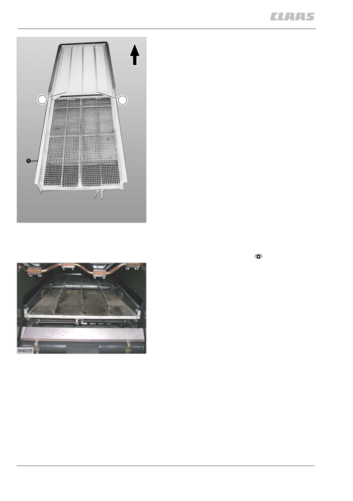
13.15.4 Cleaning the stepped preparation
floors
A heavily soiled preparation floor results in an uneven
flow of the crop to the sieves, causing overloading of
the sieves and resulting in grain losses. The stepped
preparation floor sections of the preparation floor can
be pulled out to the rear for cleaning work.
- Observe the general warnings at the beginning of
the "Maintenance" chapter.
- Loosen the nuts at the brackets (1).
- Detach the bracket (1).
1
1
148
19632
361
13 Maintenance
13.15 Cleaning unit
67089
- Suspend the stepped preparation floors at (A) and
pull them out to the rear.
- Clean the stepped preparation floors.
- Clean the guides and push in the stepped prepa-
ration floors towards the front.
- Suspend bracket and bolt on with nuts.
- Lock nuts.
A
A
149
19633
82787
13.15.5 Cleaning the sieves
- Observe the general warnings at the beginning of
the "Maintenance" chapter.
- Clean the sieves.
150
19638
362
13 Maintenance
13.16 Grain delivery
67089
13.16 Grain delivery
83199
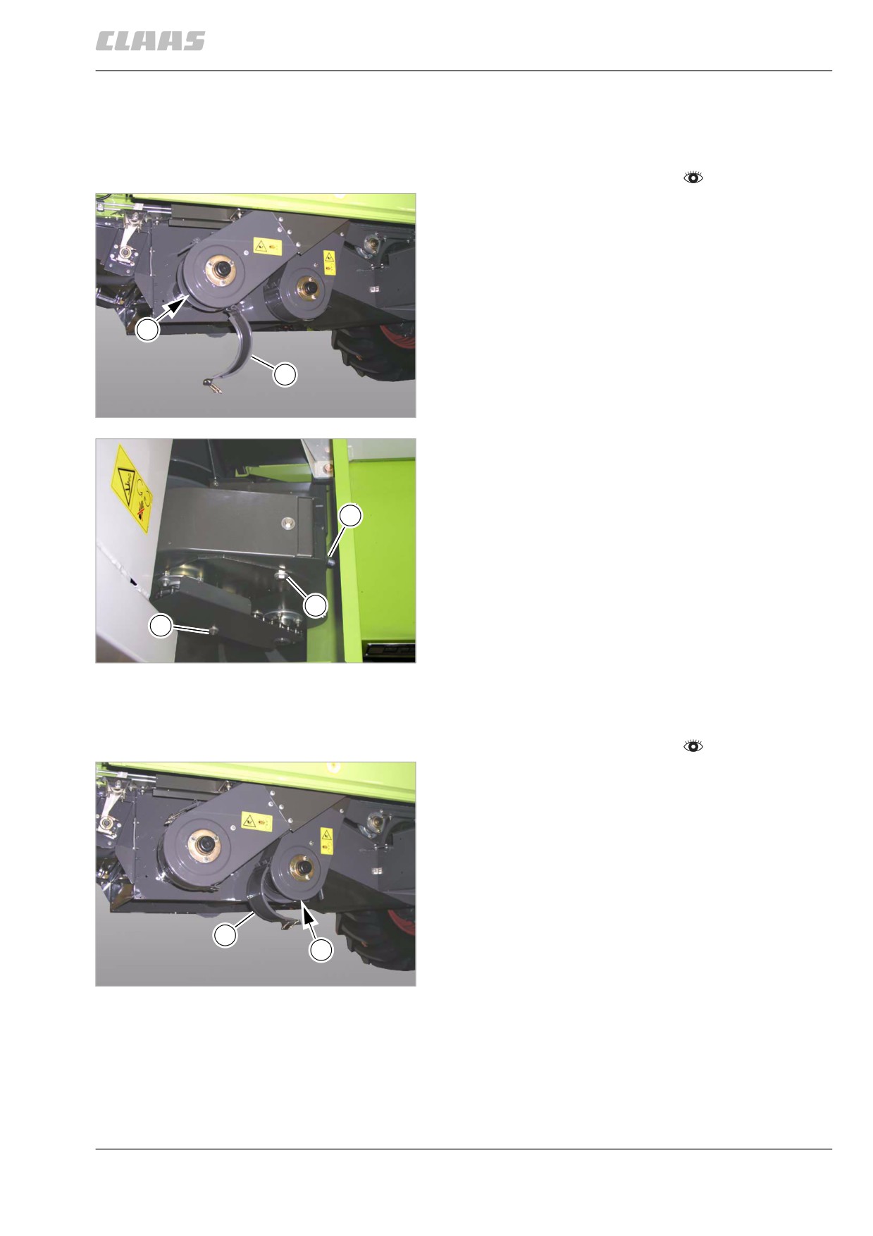
13.16.1 Adjusting the returns elevator chain
- Observe the general warnings at the beginning of
the "Maintenance" chapter.
- Check the tension of the returns elevator chain (1)
with the flap (2) open.
The returns elevator chain is correctly adjusted if the
delivery plates do not scrape against the elevator
housing and the chain can still be moved by hand on
the side at the lower sprocket.
1
- If necessary, adjust the returns elevator chain.
2
151
28687
- Adjust the returns elevator chain.
- Loosen the bolts (1) on both sides.
- Loosen bolt (2) and relax the chain.
- Adjust the nut (3) until the chain is tensioned.
3
- After tensioning, tighten the bolts (1) on both
sides.
- Tension the chain with a block tensioner and
tighten bolt (2).
1
- Close the flap.
2
152
28688
83207
13.16.2 Adjusting the grain elevator chain
- Observe the general warnings at the beginning of
the "Maintenance" chapter.
- Check the tension of the grain elevator chain (1)
with the flap (2) open.
The grain elevator chain is correctly adjusted if the
delivery plates do not scrape against the elevator
housing and the chain can still be moved by hand on
the side at the lower sprocket.
- If necessary, adjust the grain elevator chain.
2
1
153
28689
363
13 Maintenance
13.16 Grain delivery
67089
Danger!
Danger of falling!
Death or serious injuries!
- Arrange for additional safety precautions.
1
- Only enter areas protected by railings.
- Areas originally without railings must be
protected by additional railings.
-
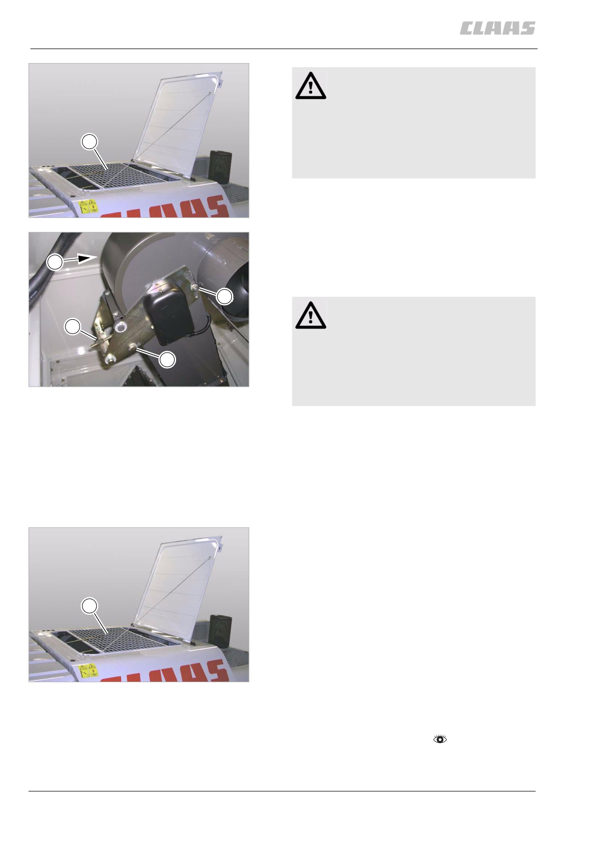
Open the grain tank cover and fold it open to the
rear as far as possible.
154
-
Remove guard (1).
29583
-
Adjust the grain elevator chain.
- Loosen bolt (1).
4
- Slacken off the nuts (3) on both sides.
- Unscrew guard (4) and check filler auger chain.
3
WARNING:
The maximum chain tension is exceeded.
2
Machine damage.
1
- Check filler auger chain tension.
- If necessary, slacken off filler auger chain
155
before tensioning the grain elevator
29584
chain.
-
- Adjust nut (2) until the chain is tensioned.
- After tensioning, tighten bolt (1) and nut (2).
- If necessary, tension filler auger chain with the
block tensioner and tighten bolt.
- Fit guard (4) and ensure a tight seat.
- Tighten the nuts (3) on both sides.
- Close the flap.
-
Fit guard (1).
–
Remove additional safety precautions.
1
156
29583
83208
13.16.3 Cleaning the auger troughs
- Observe the general warnings at the beginning of
the "Maintenance" chapter.
364
13 Maintenance
13.16 Grain delivery
67089
Warning!
Sharp edges and pointed machine parts.
Slight injuries.
2
2
- Do not touch sharp edges of the auger
flights.
- Wear safety gloves.
1
1
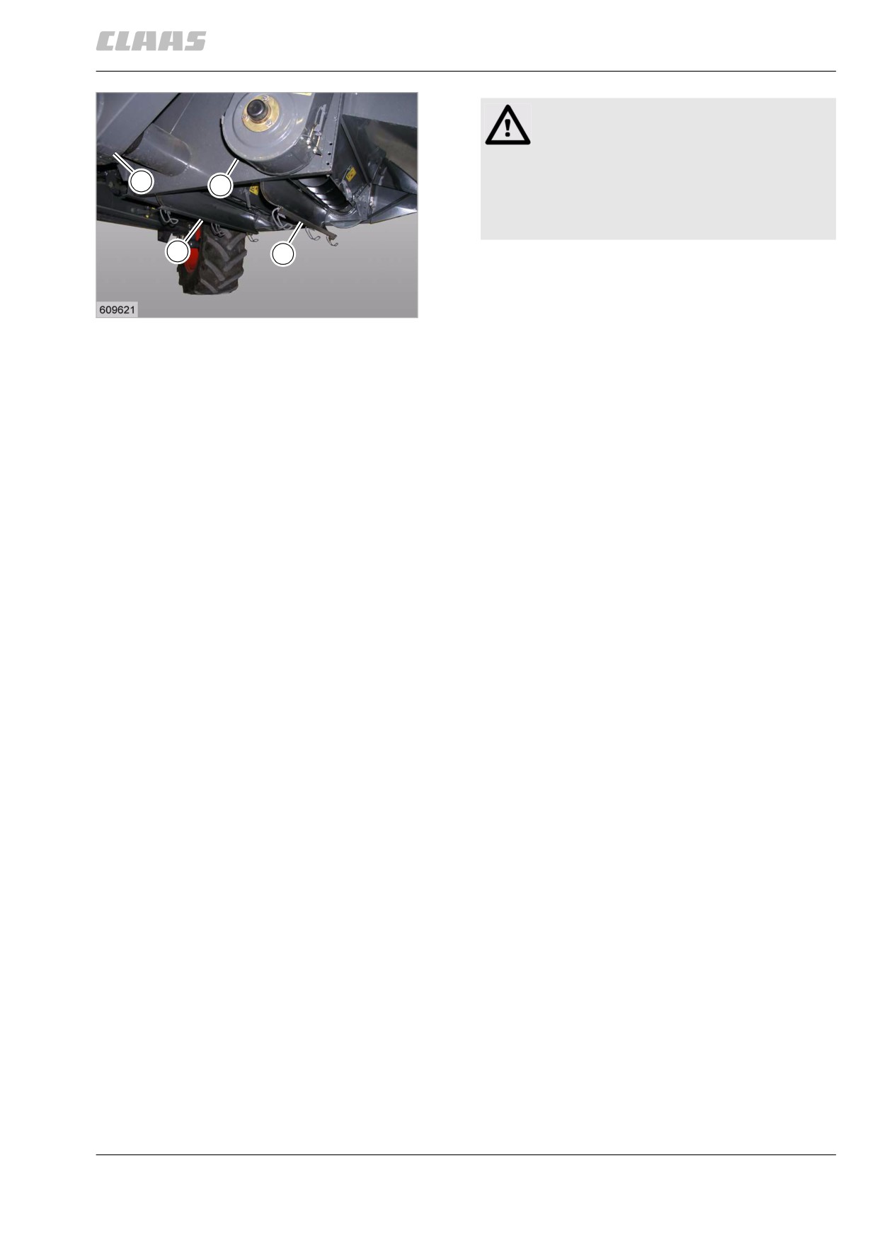
- Open the auger troughs (1).
- Clean the auger troughs.
- Close the auger troughs (1).
157
19651
- Open the flaps (2) of the elevators.
- Clean the flaps.
- Close the flaps (2) of the elevators.
365
13 Maintenance
13.16 Grain delivery
67089
79450
13.16.4 Cleaning the grain tank
- Observe the general warnings at the beginning of
the "Maintenance" chapter.
Warning!
Sharp edges and pointed machine parts.
1
Slight injuries.
- Do not touch sharp edges of the auger
flights.
- Wear safety gloves.
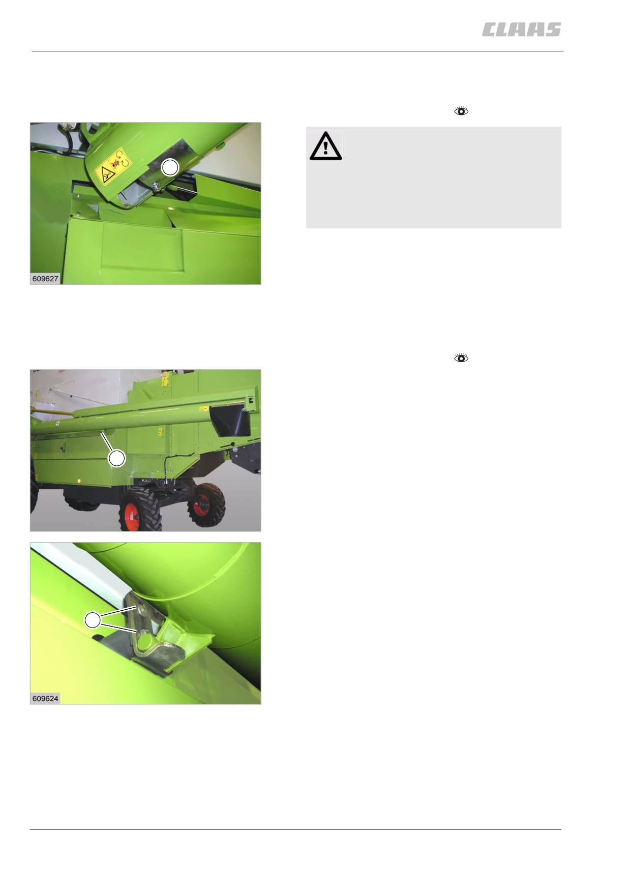
- Open cover (1).
- Clean the grain tank.
- Close flap (1).
158
19660
83151
13.16.5 Adjusting the grain tank unloading
tube support transport position
- Observe the general warnings at the beginning of
the "Maintenance" chapter.
In the transport position the grain tank unloading tube
rests on the support bracket (1).
- Adjust the support height with the two bolts (2) so
that the unloading auger tube lies safely on the
support.
1
159
28639
2
160
19659
366

13 Maintenance
13.17 Various components / Machine body
67089
13.17 Various components / Machine body
86845
13.17.1 Checking the fire extinguisher
The operational readiness of the fire extinguisher (1)
must be checked according to the details given in the
maintenance schedule.
1
The testing intervals may differ in other countries. In
such cases, the information on the fire extinguisher is
valid for the respective countries.
The date of manufacture or the date last checked is
shown on the extinguisher.
161
14530
367
14 Lubrication chart
14.1 Lubrication points
67090
14 Lubrication chart
14.1 Lubrication points
85078
14.1.1 General warnings Lubrication chart
The following general warnings are addressed in the
sections below of this chapter by means of
instructions.
Danger!
Always stop the engine before carrying out
any work on the machine.
Moving machine parts and / or unexpected
machine movement.
Death or serious injury.
- Diesel engine OFF.
- Apply parking brake.
- Remove the ignition key.
- Remove key of battery isolating
switch.
- Wait for machine parts which run on have
come to a complete halt.
- Secure machine by wheel chocks.
- Ensure that the machine cannot be
started by any third persons.
Danger!
The front attachment, reel and feeder unit may
drop uncontrolled.
Death or serious injuries!
- Apply safety locks.
- Keep a safe distance from the hazard
area.
5009
14.1.2 Lubricants
Lubricants used on the machine and on the front
attachment are subdivided into grease and chain oil.
Grease
Only use brand-name grease!
CLAAS brand-name grease:
AGRIGREASE EP 2
EP 2 Grease DIN 51502:
KP2K-25
NLGI2
368
14 Lubrication chart
14.1 Lubrication points
67090
AGRIGREASE LC 00/000
DIN 51502:
MP 00/000K-45
NLGI 00/000
Chain lubrication oil
Use only chain lubrication oil based on rape oil!
87860
14.1.3 Greasing cycles
- Observe the general warnings at the beginning
of the Lubrication chart chapter.
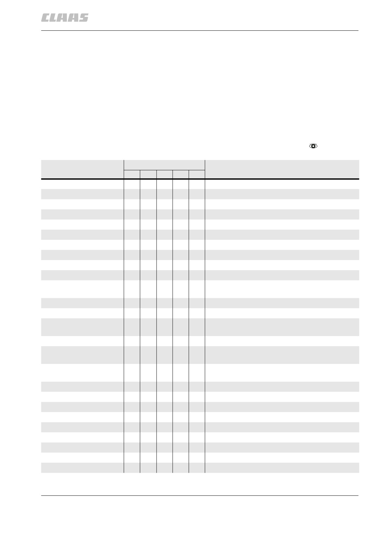
Grease point number
Working hours
Remark
10
50
100
250
500
1
•
2
•
Option
3
•
Option
4
•
5
•
6
•
7
•
8
•
9
•
10
•
11
For better grease distribution, actuate the variable
•
speed drive several times.
12
•
13
•
14
For better grease distribution, actuate the variable
•
speed drive several times.
15
•
16
For better grease distribution, actuate the variable
•
speed drive several times.
17
For better grease distribution, actuate the variable
•
speed drive several times.
18
•
19
•
20
•
21
•
22
•
23
•
24
•
Option
25
•
26
•
369
14 Lubrication chart
14.1 Lubrication points
67090
Grease point number
Working hours
Remark
10
50
100
250
500
27
For better grease distribution, actuate the variable
•
speed drive several times.
28
For better grease distribution, actuate the variable
•
speed drive several times.
29
•
Option
30
•
31
•
32
•
33
•
34
•
35
•
36
•
Option
37
•
Option
38
•
Option
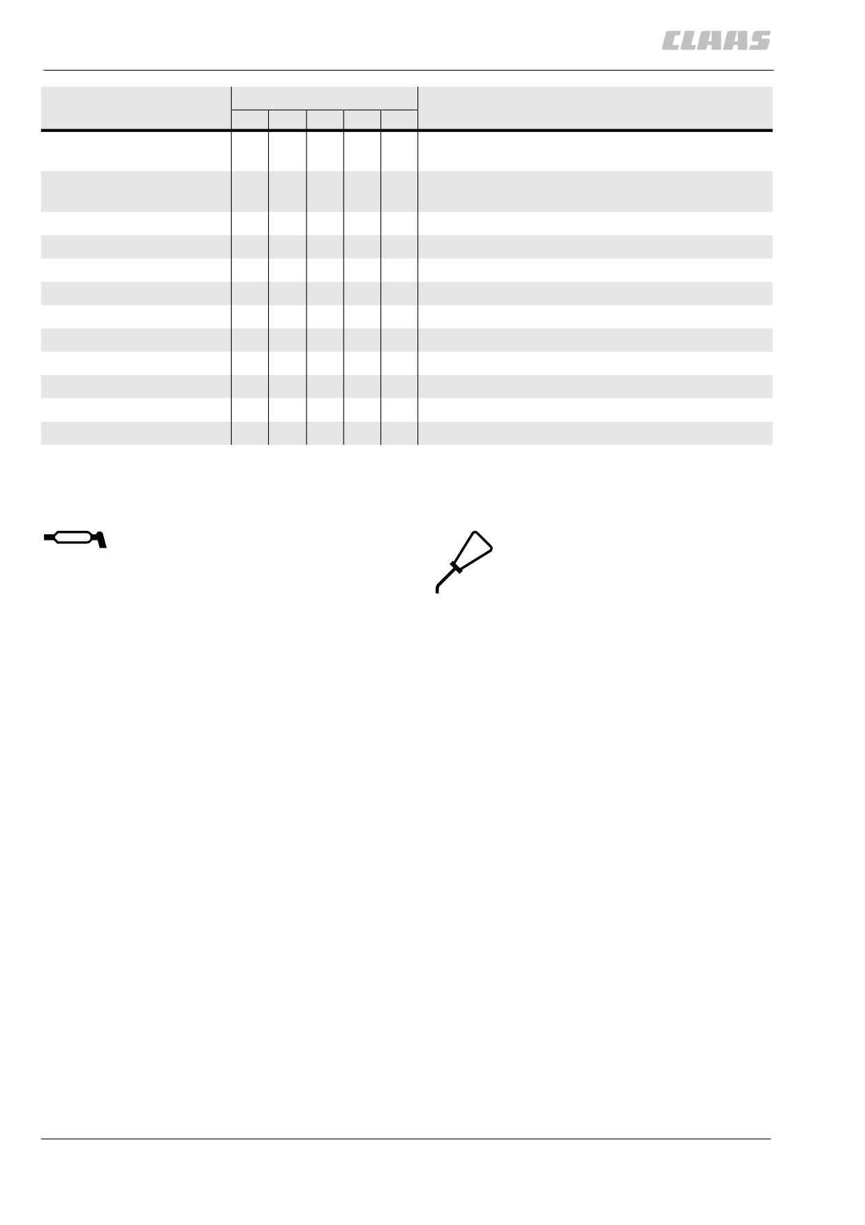
Lubricant symbols in figures
The following symbols are used in figures:
Lubricate the lubrication point.
Lubricate the lubrication point.
For grease see the lubricants chart.
For chain lubrication oil see the
lubricants chart.
370
14 Lubrication chart
14.1 Lubrication points
67090
87832
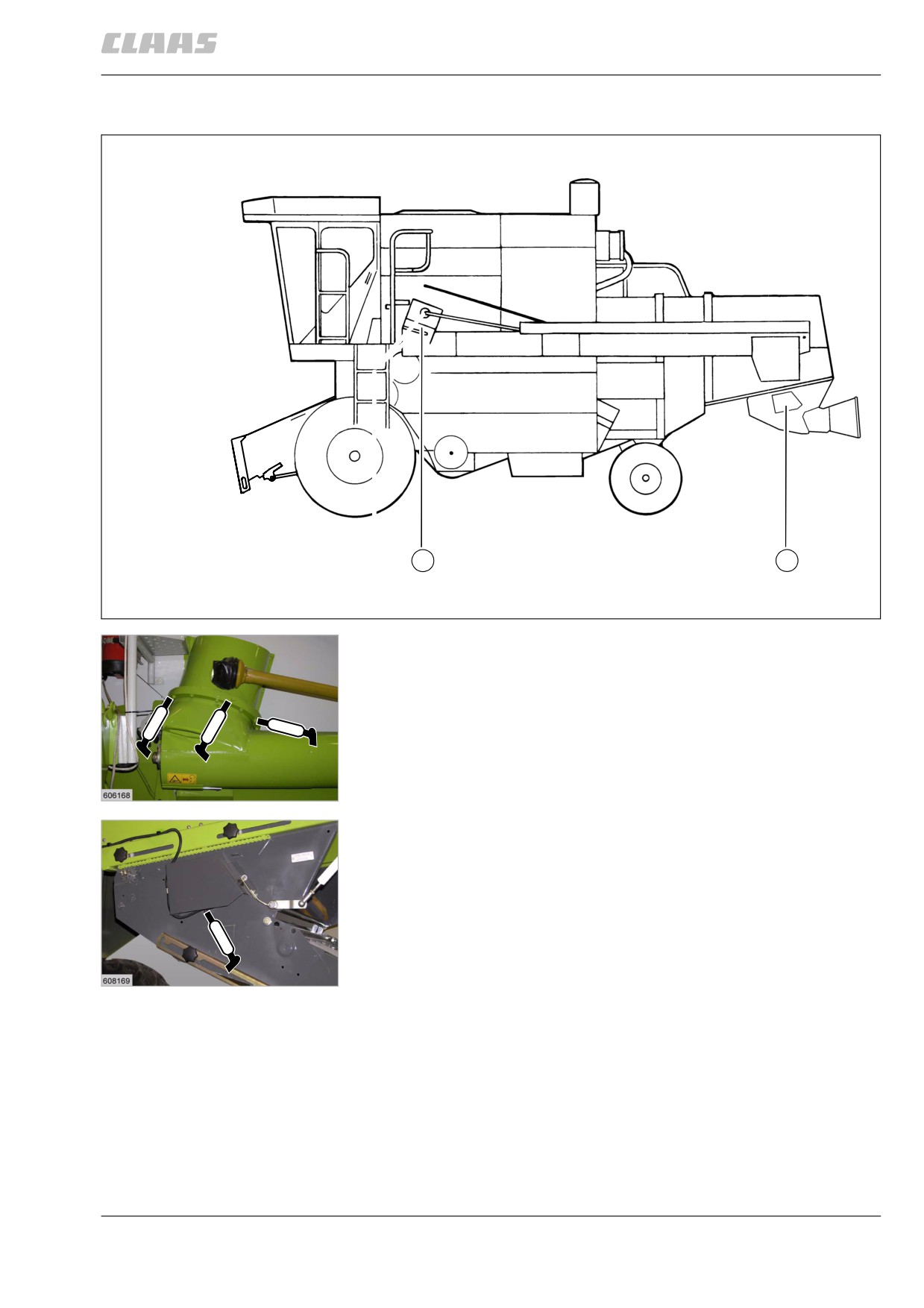
14.1.4 Lubrication points - 10 h on the left
1
2
30113
30114
1
30115
2
371