CLAAS DOMINATOR 150 / 140 / 130. Operator’s Manual - page 14
11 Fieldwork
11.6 Threshing mechanism
67087
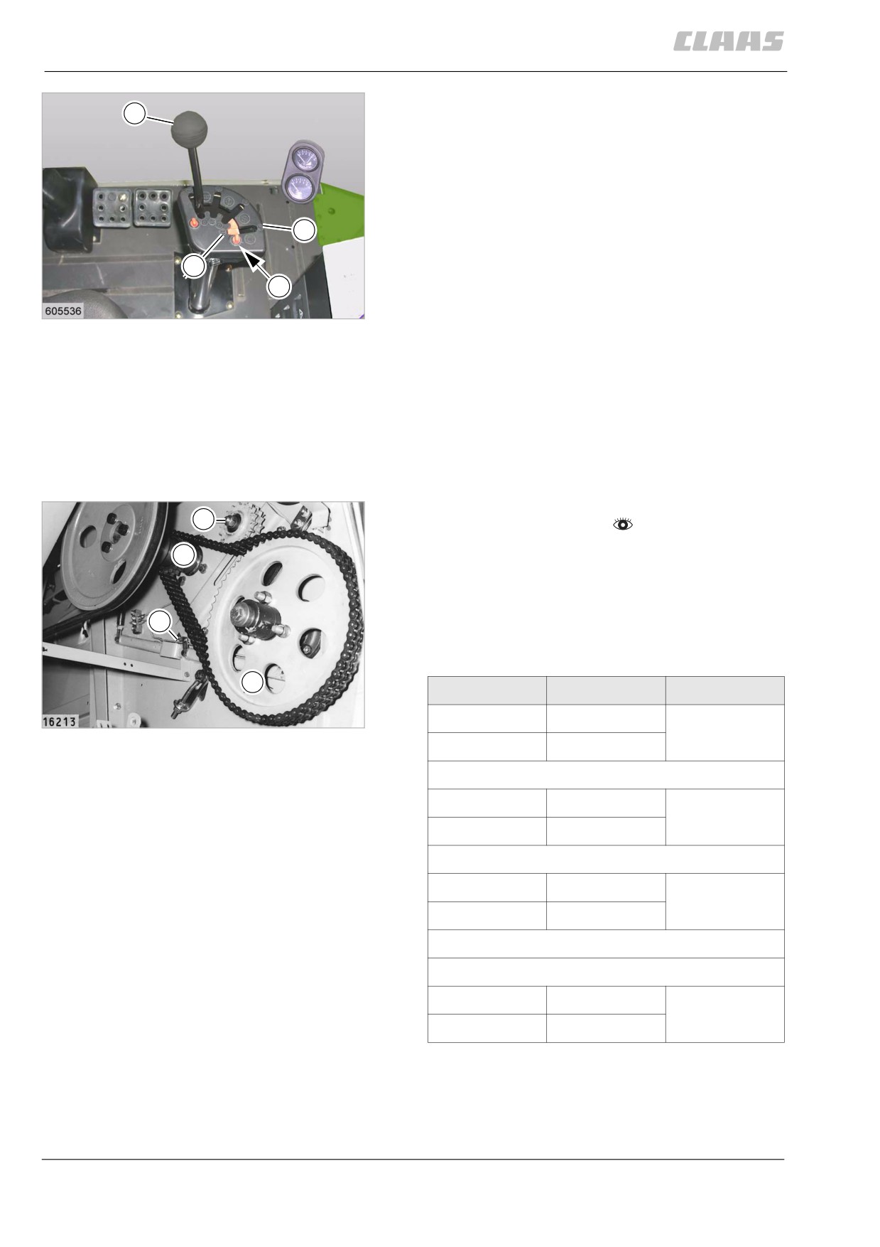
Adjusting the threshing drum speed
H
DOMINATOR 130
- Unblock the threshing drum gate (7 / 8) with
lock (Y).
Reducing the threshing drum speed
- Move lever (1) from the neutral position (N)
7
towards (7), thus reducing the threshing drum
speed.
8
Increasing the threshing drum speed
Y
- Move lever (1) from the neutral position (N)
34
towards (8), thus increasing the threshing drum
DOMINATOR 130
19409
speed.
Blocking the threshing drum gate
- Block threshing drum gate (7 / 8) with lock (Y).
Consequently, the drum speed cannot be acciden-
tally changed.
55569
11.6.7 Threshing drum two-step variable-
speed drive (chain drive)
- Observe the general warnings at the beginning of
3
the "Fieldwork" chapter.
1
An optional chain drive kit for threshing crops that
crack easily can be installed in place of the drum varia-
ble-speed drive.
Three speeds can be obtained by changing sprockets
4
(2). An additional fourth speed can be obtained by
replacing sprocket (1) on the impeller shaft.
2
Sprocket
Teeth
Speed of
35
1
17
19611
300 rpm
2
64
1
17
430 rpm
2
45
1
17
550 rpm
2
35
Additional stage:
1
15
265 rpm
2
64
For a speed of 550 rpm, the standard length of chain is
72 rollers.
212
11 Fieldwork
11.6 Threshing mechanism
67087
For 430 rpm, add a length of 6 rollers; for a speed of
300 rpm and for a speed of 265 rpm, add an additional
length of 10 rollers to the chain.
Tension the double chain moderately at tensioner bolt
(4) with the clamping bolt (3) slackened off. After ten-
sioning, tighten clamping bolt again.
Whatever drive is used, drum speed read out is pro-
vided by the tachometer in the combined instrument
gauge on the operator's platform.
213
11 Fieldwork
11.7 Separation
67087
11.7 Separation
82457
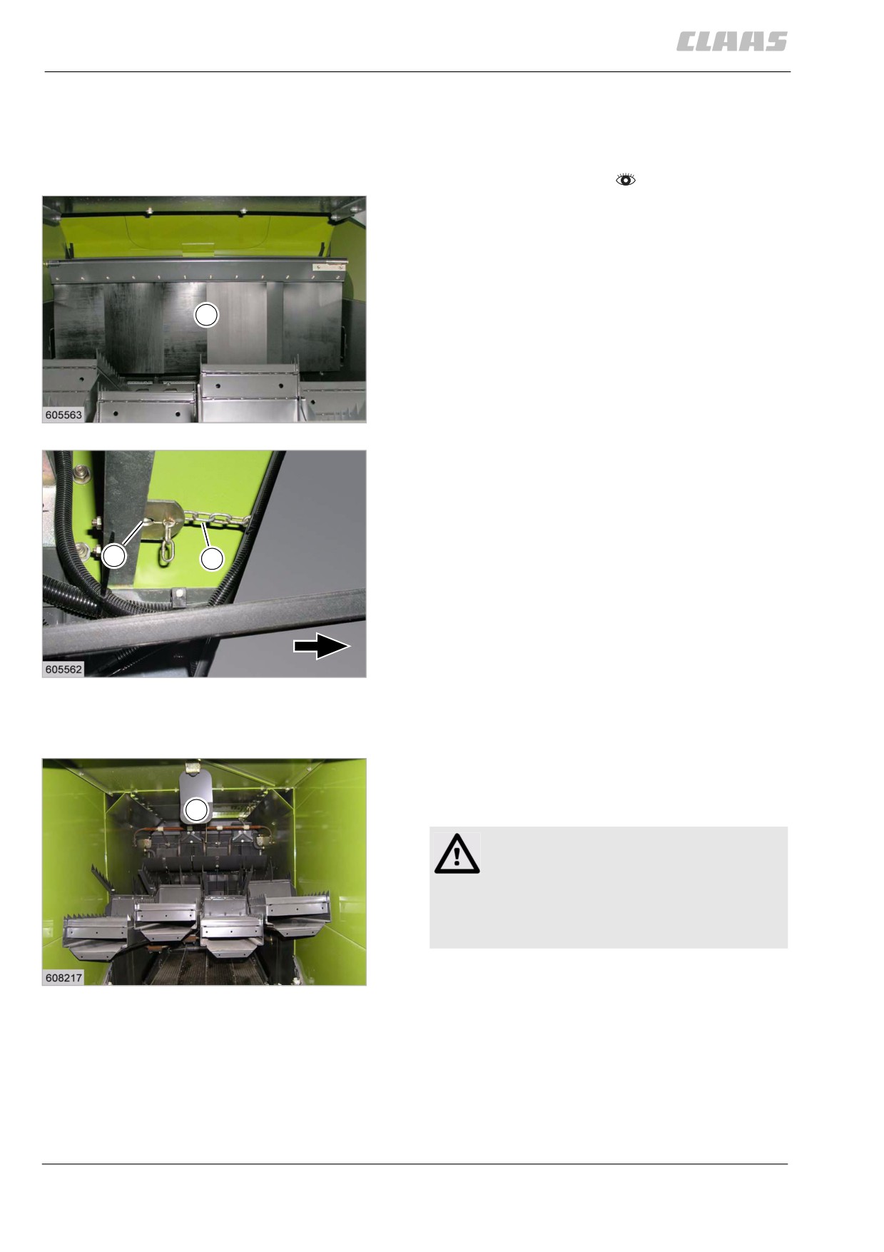
11.7.1 Adjusting the deflector curtain
- Observe the general warnings at the beginning of
the "Fieldwork" chapter.
The deflector curtain (1) can be height-adjusted on the
right side of the machine, using a chain.
In the basic grain setting, the deflector curtain is hang-
ing down freely.
Raise the curtain in heavy, long-strawed crops and
where a lot of greenstuff is encountered.
1
It is essential to lower the curtain again in short-
strawed light crops.
36
19623
- Unlock chain (2) at position (A) and adjust its
length.
The deflector curtain can be set higher or lower.
The deflector curtain can yield to the rear.
A
2
– Lock chain (2) at position (A) after the adjustment.
37
19624
82486
11.7.2 Observe the straw blockage warning
downstream of the separation stage
In case of a straw jam downstream of the separation
stage, cover (1) is actuated and the horn on the opera-
tor's platform produces a horn tone.
1
WARNING:
Straw plug.
Machine damage.
- Immediately stop the machine and
remove straw plug.
38
19625
214
11 Fieldwork
11.7 Separation
67087
82502
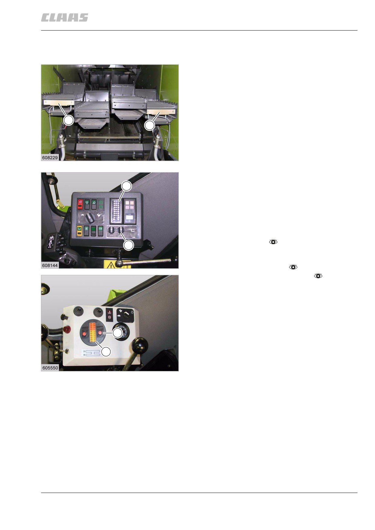
11.7.3 Adjusting the separation performance
monitor display
The cleaning and separation performance monitor
allows the operator to make full use of the capacity of
the machine.
The display (3) allows the operator to determine how
fast the machine can be driven without the reasonable
grain loss limit being exceeded.
2
Grains lost over the back of the combine with the straw
2
fall onto the sensors (2). The excited pulses are visual-
ised by the meter lights of the display (3).
The sensitivity of the separation display can be set
depending on the properties of the crop (straw mois-
39
ture, green part, grain shape, leaf content of straw).
19647
- Adjust the separation performance monitor
sensors.
3
- Set the sensitivity of the separation display and
the desired individual grain loss limit at switch (4).
The display reacts more sensitive / less sensitive,
depending on the adjusted set value.
Check the grain loss limit. Proceed as follows:
- Prepare fieldwork.
4
- Set the machine depending on the crop. See
threshing chart.
40
- Engage front attachment.
DOMINATOR 150 / 140
19558
- Engage the threshing mechanism.
- Drive the machine into the crop at the speed
appropriate for the crop.
- Stop the machine when the forth to fifth light of the
meter light (3) lights up constantly after a sufficient
distance has been covered.
- Check the losses in the swath.
4
- If loss is at an acceptable level, continue operation
with selected setting.
3
- When losses on the straw walker are too high,
increase the gauge sensitivity by about half to one
step, using switch (4).
41
DOMINATOR 130
19412
Now adjust forward speed until the fourth or fifth
light in the meter light (3) lights up again.
- When excessive losses on the straw walker con-
tinue, check the machine setting regarding
concave clearance, drum speed and deflector cur-
tain setting.
If the loss rate, indicated by the fourth or fifth light in
the meters, is acceptable, the capacity of the combine
is fully utilised at this forward speed.
215
11 Fieldwork
11.7 Separation
67087
The cleaning and separation performance monitor
should be adjusted as described to suit changing
losses in the morning, when the crop is wet with dew,
at noon when the crop is absolutely dry, and in the
evening when the crop gradually gets damp.
216
11 Fieldwork
11.7 Separation
67087
82483
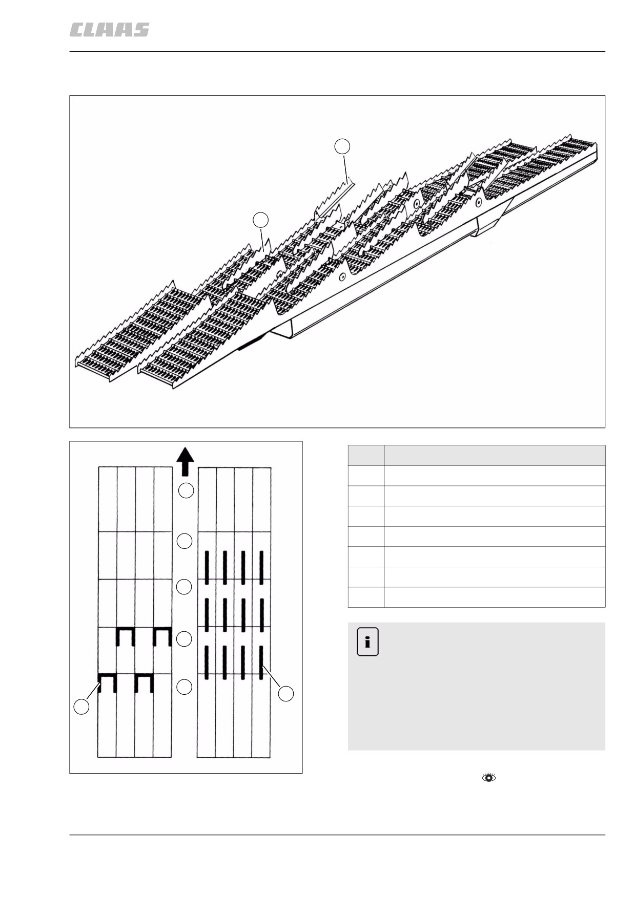
11.7.4 Installing / removing the straw walker fishback
1
2
28794
42
Designation
1
Side risers
F
2
Rise riser (also for grain)
1st
Straw walker step 1
2nd
Straw walker step 2
1.
3rd
Straw walker step 3
4th
Straw walker step 4
2.
F
Direction of travel
Note!
3.
Risers can collide with the agitator tines of the
intensive separation system.
Machine damage.
4.
2
- Install risers at a safe distance from the
1
agitator tines of the intensive separation
system.
- Check free wheel.
43
- Observe the general warnings at the beginning of
28793
the "Fieldwork" chapter.
217
11 Fieldwork
11.7 Separation
67087
For more intense loosening-up, especially with wet
and heavy straw, risers can be fitted on the straw
walker racks.
The risers can also be installed in combination to
achieve an even better tumbling action.
If required, parallel risers (3) can also be fitted to the
follow-up steps of the straw walkers.
218
11 Fieldwork
11.8 Cleaning unit
67087
11.8 Cleaning unit
82875
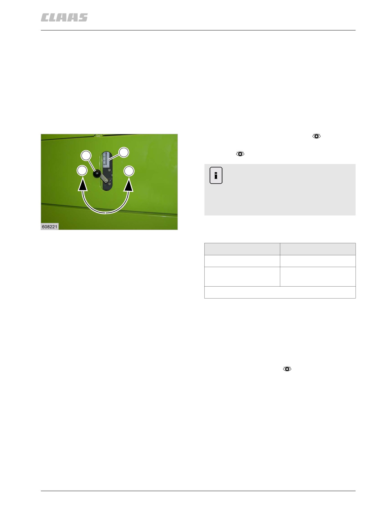
11.8.1 Adjusting the fan speed
The cleaning fan blows all light particles out of the
machine from below. Excessive “matting” of grain,
chaff and broken straw on the upper sieve can be pre-
vented by having sufficient volume of wind. The wind
blast also helps to fluff up the material.
The speed can be infinitely varied with crank (1). The
crank is decelerated by a spring and is therefore pro-
tected against unintended misadjustments.
- Engage the threshing mechanism.
- Set the diesel engine speed to fast idling
2
speed.
1
+
-
Note!
Constructive conditions.
Machine damage.
- Adjust the fan speed only when the
threshing mechanism is engaged.
- Adjust fan speed with crank (1) until the desired
44
19634
speed is shown on gauge (2).
Fan speed
Higher
Turn crank clockwise (+)
Lower
Turn crank anti-
clockwise (-)
Gauge value x 100 = approx. fan speed in rpm.
The speed must be set depending on the crop. See
threshing chart.
Basic rule: Set the fan speed as high as possible,
depending on crop conditions.
82936
11.8.2 Adjusting the wind board
- Observe the general warnings at the beginning of
the "Fieldwork" chapter.
219
11 Fieldwork
11.8 Cleaning unit
67087
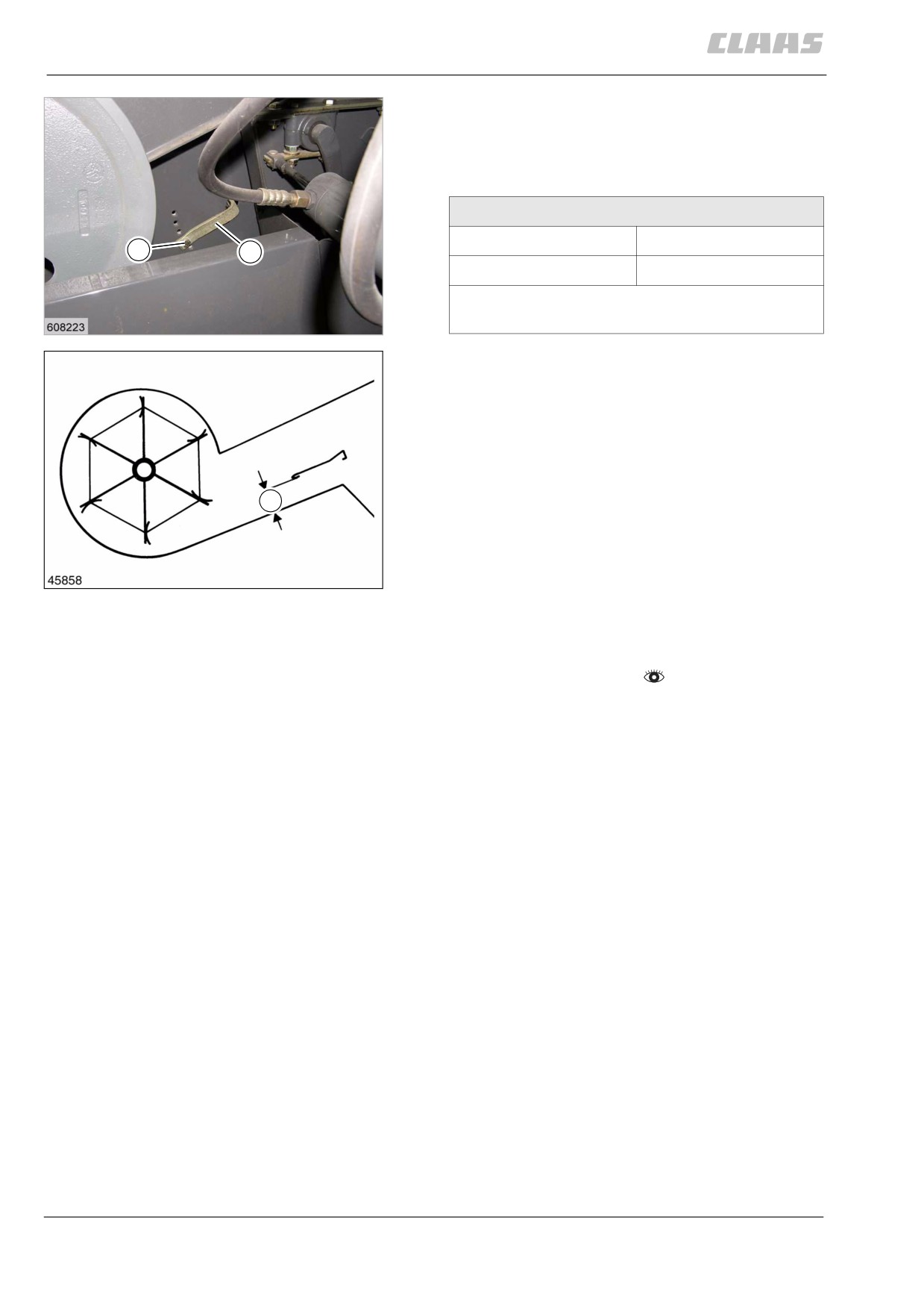
Use the wind board (1) to adjust the wind direction in
the air duct.
For heavy crops, adjust the wind board steeper, for
light crops, adjust the wind board less steeply.
Wind board basic adjustment
Lever (3)
2nd hole from below
2.
3
Dimension (X)
approx. 68 mm
Dimensions (X) and (Y) are factory-set. When
installing new parts, check the dimension.
45
19636
- Unscrew bolt (2).
Move wind boards to the desired positions.
Screw in bolt (2).
X
46
19637
82949
11.8.3 Adjusting the sieves manually
- Observe the general warnings at the beginning of
the "Fieldwork" chapter.
220
11 Fieldwork
11.8 Cleaning unit
67087
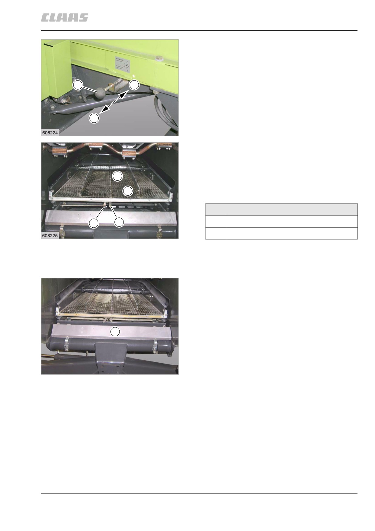
The frogmouth sieves are adjustable for all grain sizes
by levers.
Lever (5) is used to adjust the upper frogmouth sieve
over its full length, including the returns passthrough
area (4).
7
A
Lever (6) is used to adjust only the returns pass-
through area (4).
- Adjust the grain sieving (3) of the upper frogmouth
sieve with lever (5) so that the grain quantity is
B
sieved after three fourths of the sieve area has
been sieved.
47
19639
- Always set the returns sieving (4) of the upper
frogmouth sieve with lever (5) for all crop types
wider than the grain sieving (3), so as to prevent
ears not threshed out from falling through and get-
ting into the returns. Check returns.
3
- Adjust the lower frogmouth sieve with the lever (7)
so that the crop in the grain tank corresponds to
4
the desired quality. Check returns.
Lower sieve adjusting lever (7)
5
6
A
Narrower sieve spacing
48
B
Wider sieve spacing
19638
82682
11.8.4 Adjusting the cleaning performance
monitor display
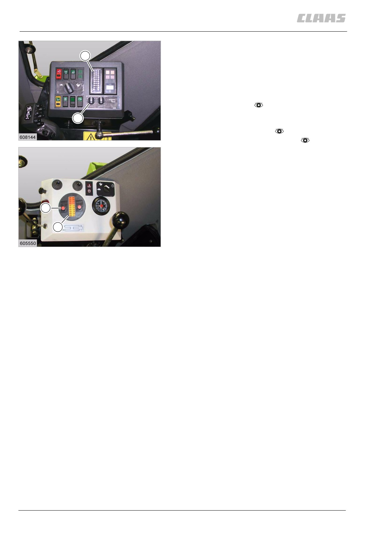
The cleaning and separation performance monitor
allows the operator to make full use of the capacity of
the machine.
The display (3) allows the operator to determine how
fast the machine can be driven without the reasonable
grain loss limit being exceeded.
2
The grains carried out through the sieve fall on the
sensor (2). The excited pulses are visualised by the
meter lights of the display (3).
The sensitivity of the cleaning system display can be
adjusted depending on the properties of the crop
49
(grain moisture, grain shape, green part).
19648
221
11 Fieldwork
11.8 Cleaning unit
67087
- Adjust the cleaning performance monitor sensors.
- Set the sensitivity of the cleaning display and the
5
desired individual grain loss limit at switch (6).
The display reacts more sensitive / less sensitive,
depending on the adjusted set value.
Check the grain loss limit. Proceed as follows:
- Prepare fieldwork.
- Set the machine depending on the crop. See
6
threshing chart.
- Engage front attachment.
50
- Engage the threshing mechanism.
DOMINATOR 150 / 140
19558
- Drive the machine into the crop at the speed
appropriate for the crop.
- Stop the machine when the forth to fifth light of the
meter light (5) lights up constantly after a sufficient
distance has been covered.
- Check the losses in the swath.
- If loss is at an acceptable level, continue operation
6
with selected setting.
- When losses on the sieve are too high, increase
the gauge sensitivity by about half to one step,
5
using switch (6).
51
Now adjust forward speed until the fourth or fifth
DOMINATOR 130
19412
light in the meter light (5) lights up again.
- When excessive losses on the sieve continue,
check the machine setting regarding concave
clearance, drum speed, fan speed and sieve
setting.
When the cleaning is properly adjusted, one of the
lights at the bottom of the meter light (5) lights up.
The cleaning and separation performance monitor
should be adjusted as described to suit changing
losses in the morning, when the crop is wet with dew,
at noon when the crop is absolutely dry, and in the
evening when the crop gradually gets damp.
222
11 Fieldwork
11.9 Crop receptacle / straw receptacle
67087
11.9 Crop receptacle / straw receptacle
83223
11.9.1 Putting the straw chopper into opera-
tion (swinging the standard spreader to
chopping position)
- Observe the general warnings at the beginning of
the "Fieldwork" chapter.
Danger!
Machine components may run on although the
drive has been shut down.
Death or serious injury.
- Never touch any machine parts that are
running on.
- Wait until all machine parts have stopped
moving.
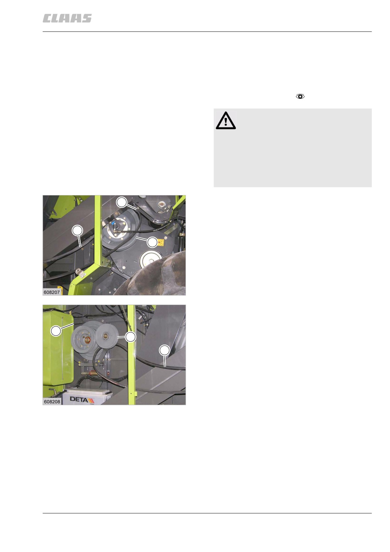
- Open the right side cover.
2
- Unhinge belt (1) from bracket (2) and install it on
pulley (3).
1
3
52
19671
- Check belt (5). The belt (5) must make contact
with all pulleys, jockey pulleys and guide rollers.
Provide contact of belt if required.
5
- Unhinge belt (1) from bracket of jockey pulley (4).
4
1
53
19672
223
11 Fieldwork
11.9 Crop receptacle / straw receptacle
67087
Warning!
1
Pinch points during assembly work.
Limbs may be bruised.
- Keep your limbs away from the hazard
area.
8
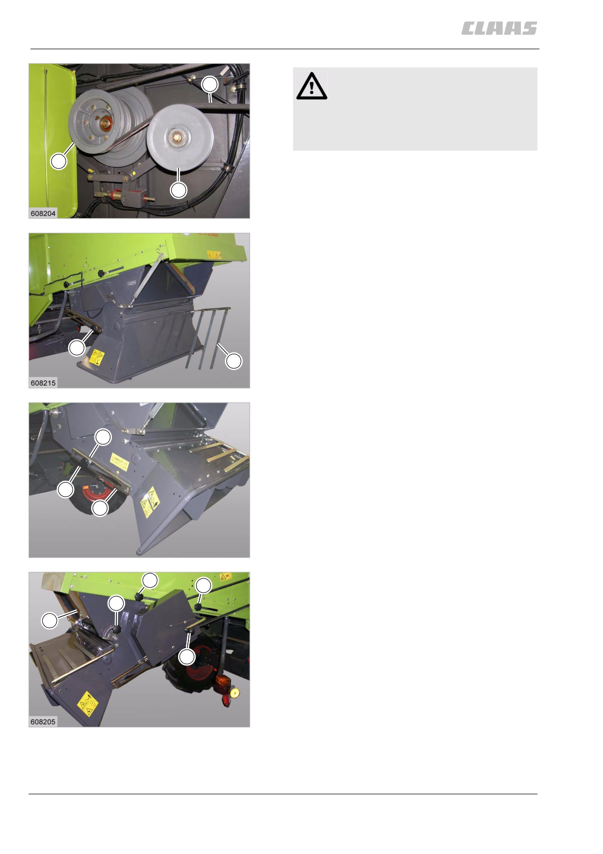
- Lay belt (1) on the inner side of the elevator and
install it on pulley (8) via jockey pulley (4). To do
4
this, push down jockey pulley (4).
54
19663
- Loosen turn locks (9) on both sides.
- Pull finger rake (10) from its lock, fold it down and
let it engage so that the rake makes contact with
the spreader.
9
10
55
19670
- Lift the sheet metal plate (11) on the left side.
Raise the standard spreader until the plates
engage in the detents (B) on both sides.
B
- Bolt down turn locks (9) on both sides.
9
11
56
28707
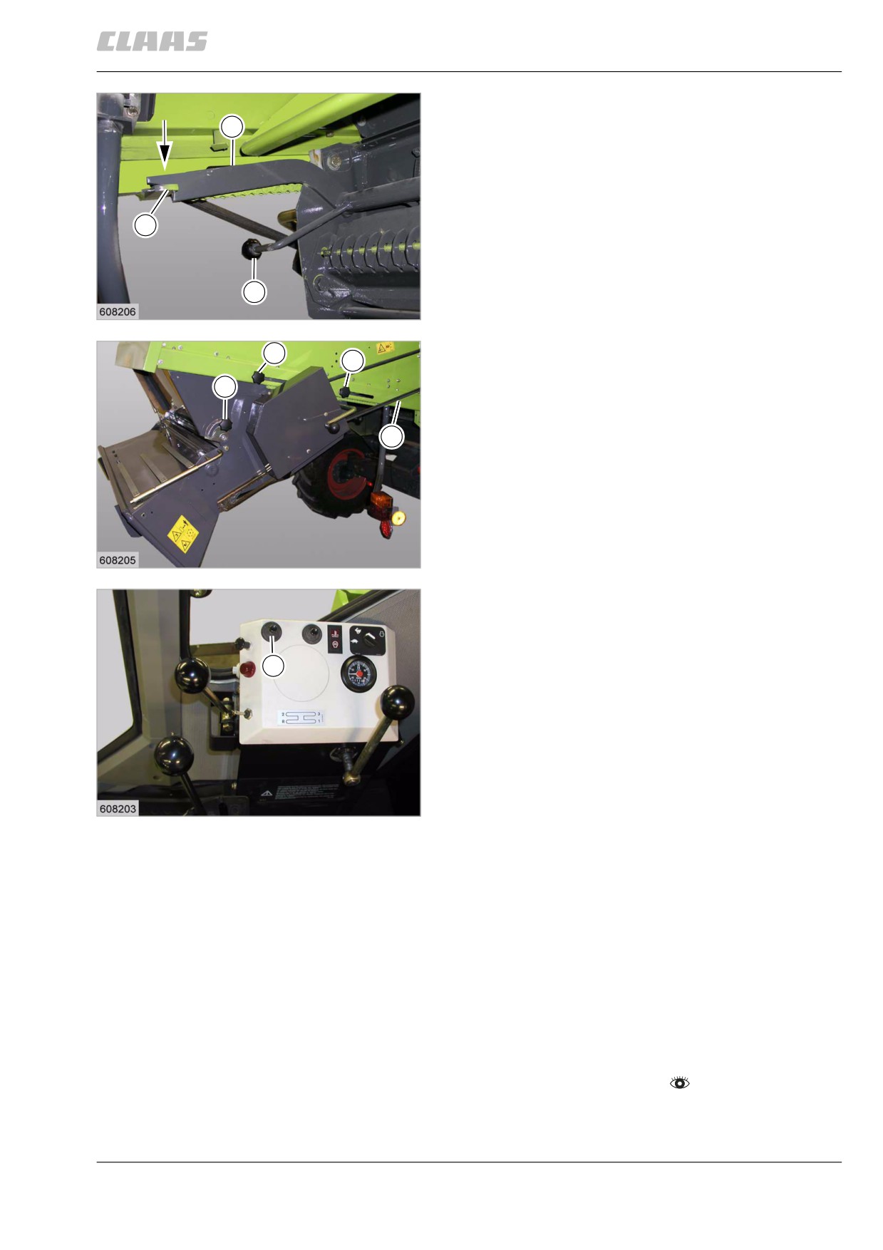
- Loosen turn locks (12) on both sides.
12
12
- Loosen turn lock (13) on the right side.
13
- Move the straw chopper to the rear, using
crank (14).
15
At the same time the straw guide plate (15) is
swung backwards.
14
57
19664
224
11 Fieldwork
11.9 Crop receptacle / straw receptacle
67087
- Use lever (17) for raising support (16) to rest on
the keeper (18).
16
18
17
58
19665
- Bolt down turn locks (12) on both sides.
12
12
- Tighten the turn lock (13).
13
- Check belt (5). The belt (5) must make contact
with all pulleys, jockey pulleys and guide rollers.
Provide contact of belt if required.
5
- Close the right side cover.
59
19664
Switching on the straw chopper function monitor
DOMINATOR 130 (optional equipment)
The straw chopper speed monitor must be switched on
when putting the straw chopper into operation (swing-
1
ing the standard spreader to chopping position), using
the pull switch (1).
When the chopper is standing still while the pull switch
is ON, the horn on the operator's platform produces a
horn sound. The straw chopper indicator light in the
vehicle information unit is also activated.
60
19554
Straw chopper function monitor
DOMINATOR 150 / 140 (optional equipment)
The straw chopper speed monitor is switched on auto-
matically when putting the straw chopper into
operation (swinging the standard spreader to chopping
position).
83284
11.9.2 Putting the straw chopper out of
operation (swinging the standard spreader
to swathing position)
- Observe the general warnings at the beginning of
the "Fieldwork" chapter.
225
11 Fieldwork
11.9 Crop receptacle / straw receptacle
67087
Danger!
The cutting cylinders of the straw chopper can
run on even if the drive is switched off.
Death or serious injuries!
- Never touch any machine parts that con-
tinue running.
- Wait until all machine parts have com-
pletely stopped moving.
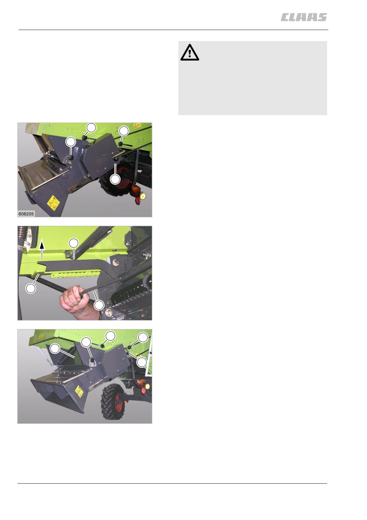
- Loosen turn locks (12) on both sides.
12
12
- Loosen turn lock (13) on the right side.
13
- Relocate the straw chopper slightly to the rear for
relieving the load on support (16), using
crank (14).
14
61
19664
- Use lever (17) for lifting support (16) over the
keeper (18).
16
18
17
62
28710
- Move the straw chopper to the front, using
12
14
crank (14).
13
15
At the same time the straw guide plate (15) is
swung forward.
12
- Bolt down turn locks (12) on both sides.
- Tighten the turn lock (13).
63
28748
226
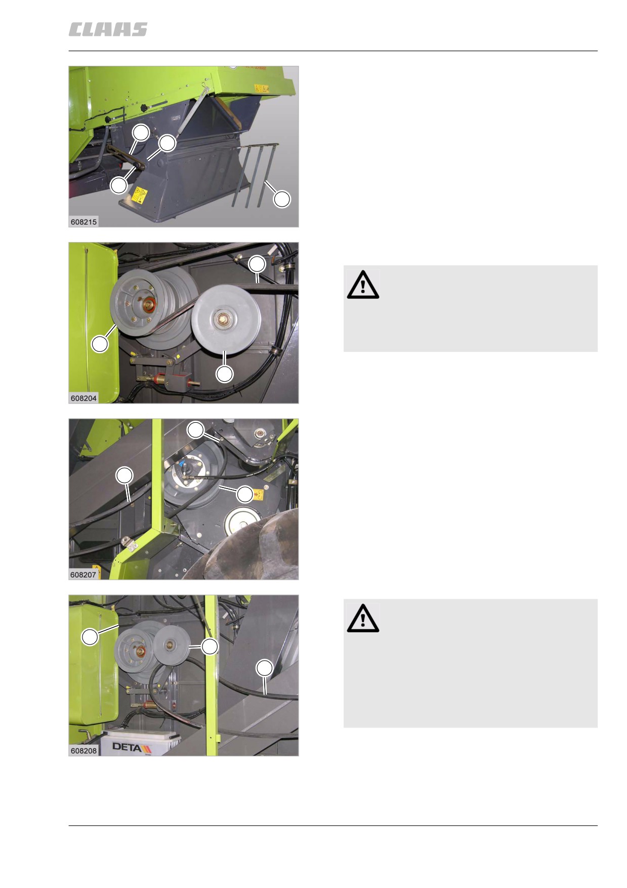
11 Fieldwork
11.9 Crop receptacle / straw receptacle
67087
-
Loosen turn locks (9) on both sides.
–
Lift the sheet metal plate (11) on the left side.
Swing the standard spreader all the way down
until the sheet metal plates on both sides make
contact at position (C).
11
-
Bolt down turn locks (9) on both sides.
C
–
Pull finger rake (10) from its lock, fold it up and
engage it.
9
10
64
19670
-
Open the right side cover.
1
Warning!
Pinch points during assembly work.
Limbs may be bruised.
- Keep your limbs away from the hazard
8
area.
-
Remove belt (1) from pulley (8). To do this, push
4
down jockey pulley (4).
65
19663
-
Remove belt (1) from pulley (3) and suspend it on
2
bracket (2).
1
3
66
19671
Caution
Rotating and moving machine parts.
5
4
Machine damage.
- The component must not touch rotating
1
machine parts.
- Keep a sufficient distance from all rotating
and moving machine parts.
- Comply with instructions.
- Lay belt (1) on the outer side of the elevator and
67
suspend it on the bracket of jockey pulley (4).
19672
- Check belt (5). The belt (5) must make contact
with all pulleys, jockey pulleys and guide rollers.
Provide contact of belt if required.
227