CLAAS DOMINATOR 150 / 140 / 130. Operator’s Manual - page 13
11 Fieldwork
11.3 Considerations before combining
67087
11.3 Considerations before combining
69384
11.3.1 When combining, remember:
-
Wait until the crop has fully ripened - do not com-
bine beforehand! (Higher yield, less moisture
content and easier threshing are the result.)
-
Where the heads are bent, install grain lifters
close together. Where the crop is lodged, install
grain lifters further apart (on every fourth to sixth
cutterbar finger).
-
Where straw and grain are brittle, set the concave
wider and reduce the threshing drum speed. Too
much short straw impedes the cleaning process.
Cracked grain lowers the quality.
-
Where the straw is long, damp and tough, reduce
the concave clearance and increase the threshing
drum speed.
-
Under damp conditions and where crops are also
grown through with greenstuff, clean the concave,
straw walkers and sieves regularly.
-
Remember that the vital part of the cleaning proc-
ess is the blast of the fan. Prevent the forming of
»mats« on the sieves and unnecessary grain
losses by using enough wind, adjusting the frog-
mouth sieve correctly and using a flat sieve of
sufficient hole size.
-
When combining crops in which it is hard to
remove the awns, additional rasp bars can be fit-
ted to the concave.
-
To get the best results from your combine run it at
the right speed. Therefore, check the speed on
the straw walker shaft before the harvest. The cor-
rect speed is 220-5 rpm.
-
Correct cleaning of the air filter as well as clean
fuel and regular oil changes are essential for high
performance and long life of the engine.
196
11 Fieldwork
11.4 Front attachment
67087
11.4 Front attachment
82054
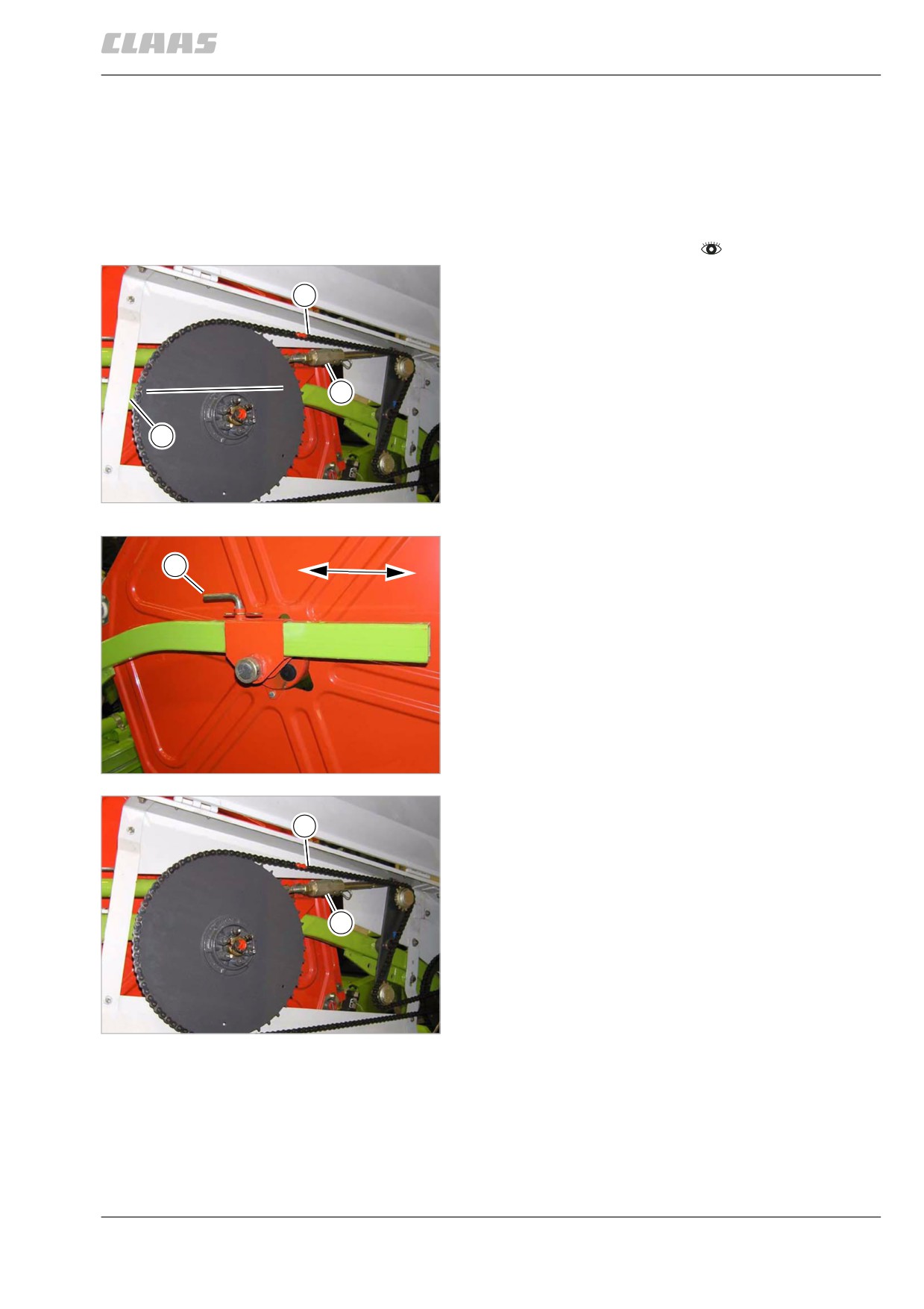
11.4.1 Adjusting the reel horizontally
(mechanically)
- Raise / lower reel until the reel poles (2) are in a
horizontal position.
- Observe the general warnings at the beginning of
the "Fieldwork" chapter.
- Relieve chain tension. To this end, pull chain down
at position (A) as far as possible and fit the spring
A
clip (1) into the front hole.
The spring-loaded cylinder is now blocked.
1
2
2
28386
- Unlock and pull out pin (1) on both sides.
1
- Adjust reel by hand.
- Insert pin (1) on both sides and secure with spring
clip.
3
28387
- Tension the chain. To this end, pull chain down at
position (A) as far as possible and fit the spring
A
clip (1) into the rear hole.
The spring-loaded cylinder now keeps the chain under
constant tension.
1
4
28386
197
11 Fieldwork
11.4 Front attachment
67087
82037
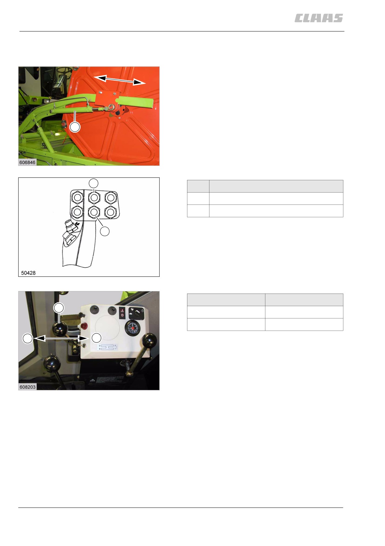
11.4.2 Adjusting the reel horizontally
(hydraulically)
The reel can be adjusted horizontally from the opera-
tor's platform to match crop conditions by means of the
two horizontal double-acting hydraulic cylinders (1).
1
5
19552
3
Function
3
Reel forward
4
Reel reverse
4
6
DOMINATOR 150 / 140
19410
Lever (1) in direction
Function
1
A
Reel forward
B
Reel reverse
A
B
7
DOMINATOR 130
19554
82058
11.4.3 Adjusting the reel circumferential speed
The reel circumferential speed must be adapted to the
ground speed. The reel speed should be slightly
higher than the ground speed.
198
11 Fieldwork
11.4 Front attachment
67087
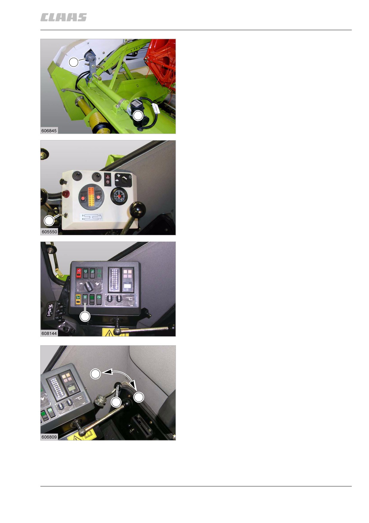
Adjusting the reel circumferential speed (electric)
The speed can be infinitely varied via the electric
motor (1) and variable-speed drive (2) from the opera-
2
tor's platform.
- Actuate switch (3) and adjust the reel circumferen-
tial speed.
1
8
19557
3
9
DOMINATOR 130
19412
3
10
DOMINATOR 150 / 140
19558
Adjusting the reel circumferential speed
(mechanically)
The speed can be infinitely adjusted from the opera-
-
tor's platform by means of crank (1).
- Increasing the reel circumferential speed = Turn
crank in + direction
+
1
- Reducing the reel circumferential speed = Turn
crank in - direction
Vary the reel circumferential speed only when the cut-
terbar is operating.
11
19530
199
11 Fieldwork
11.5 Feeder unit
67087
11.5 Feeder unit
82138
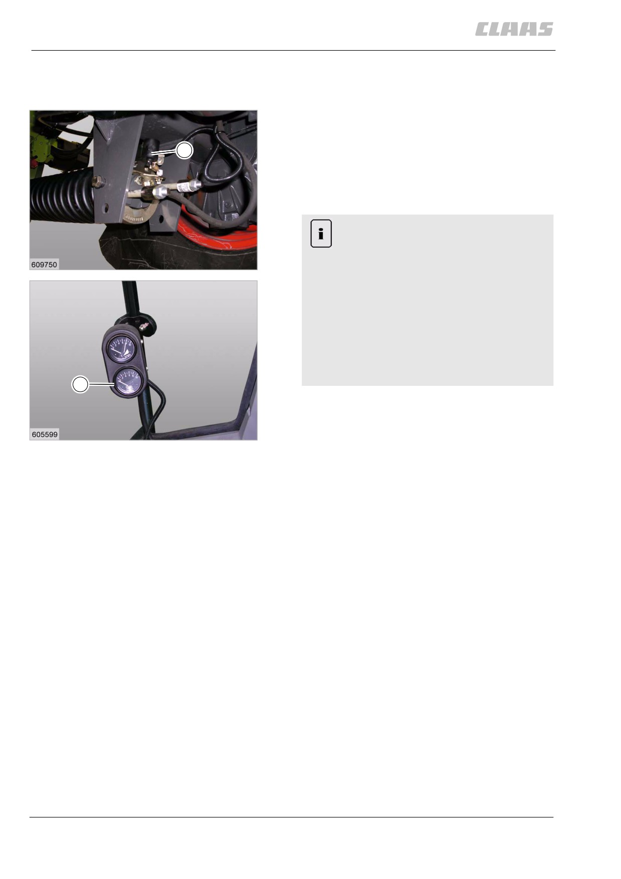
11.5.1 Reading the ground pressure
Sensor (1) shows the front attachment ground pres-
sure on gauge (B). The sensor on the right cylinder
cannot be adjusted.
1
- Lower the front attachment during threshing until
the pointer of gauge (B) is in the upper range at „9
- 10“. The skids should never have ground con-
tact. Raise / lower front attachment if required.
Note!
Uneconomic use of machine and of front
attachment.
12
19599
High fuel consumption.
High wear on the front attachment.
- The further the pointer on gauge (B) falls
towards "0“, the higher the front attach-
ment ground pressure.
- Do not set the ground pressure unneces-
sarily high.
Raise the front attachment if required.
B
13
19601
200
11 Fieldwork
11.5 Feeder unit
67087
82105
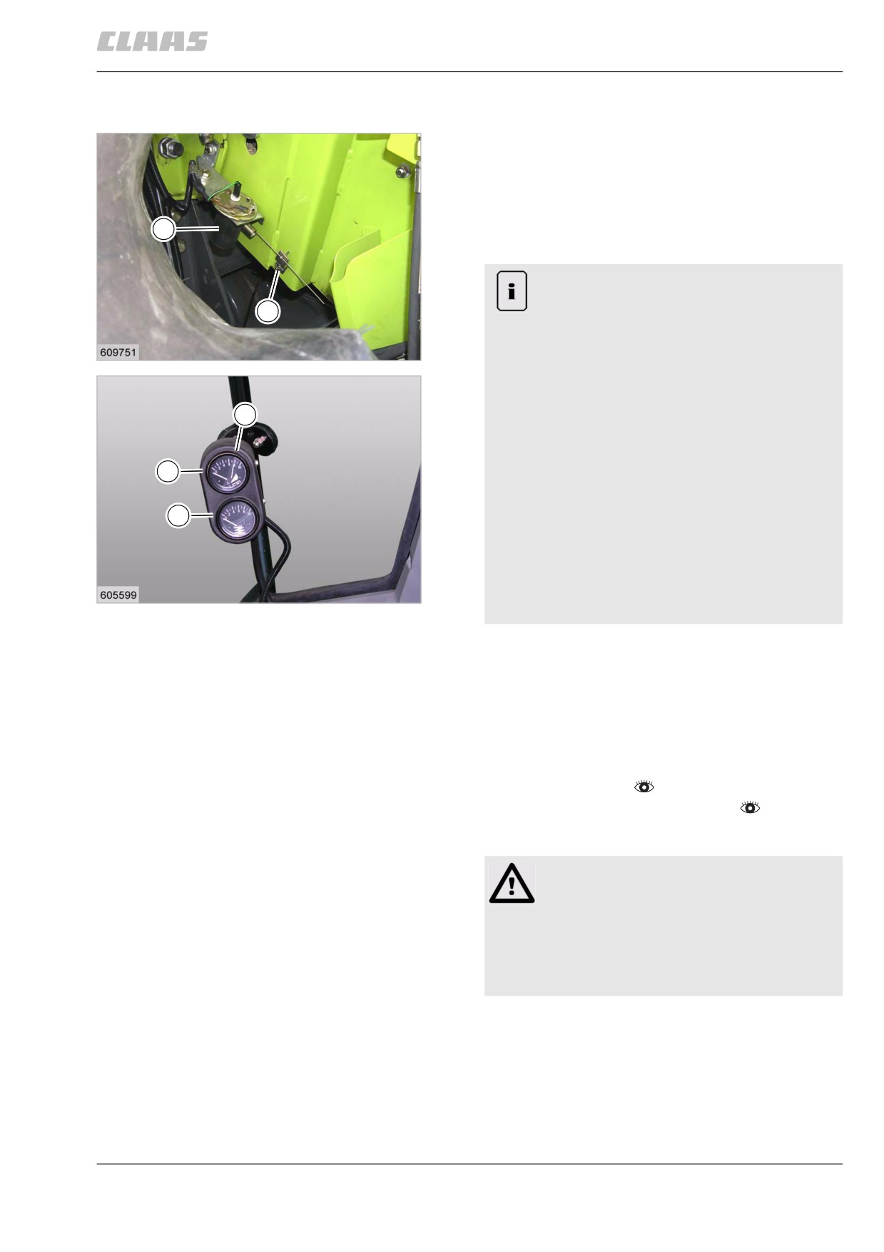
11.5.2 Reading the cutting height
The sender (1) indicates the front attachment cutting
height above the ground on gauge (A).
- Lower the front attachment during threshing until
the pointer of gauge (A) is in the upper range at
"9" (9 = about 100 mm cutting height). Raise /
1
lower front attachment if required.
Note!
Uneconomic use of machine and of front
2
attachment.
High fuel consumption.
14
19602
High wear on the front attachment.
- The further the pointer on gauge (B) falls
9
towards "0“, the higher the front attach-
ment ground pressure.
- Do not set the ground pressure unneces-
A
sarily high.
Raise / lower front attachment if required.
B
- The further the pointer on gauge (A) falls
towards "0“, the lower the front attach-
ment cutting height is above the ground.
- Do not set the cutting height unnecessar-
15
ily low.
19601
Raise / lower front attachment if required.
73212
11.5.3 Reversing the front attachment / feeder
unit
In case of clogging of the front attachment / feed rake
conveyor, the drive of the front attachment / feed rake
conveyor can be rotated backwards via a hydrostatic
motor.
- Prepare fieldwork.
- Engage the threshing mechanism.
- Disengage the front attachment.
Caution!
Machine components may run on although the
drive has been shut down.
Machine damage.
- Wait for all machine components to come
to complete stop.
201
11 Fieldwork
11.5 Feeder unit
67087
Danger!
Engaging / reversing the feeder unit without a
front attachment fitted.
Death or serious injuries.
- Fit the front attachment.
- Never engage / reverse the feeder unit
without the front attachment being fitted.
1
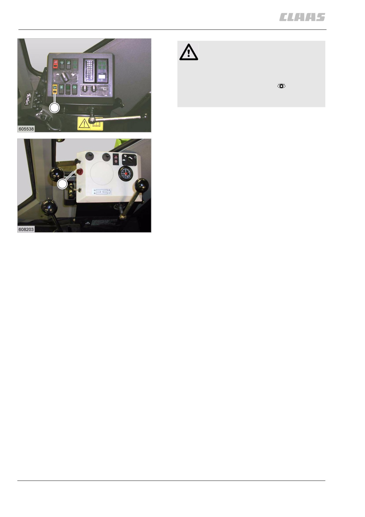
- Turn on the switch (1) until the clogging is
removed.
16
DOMINATOR 150 / 140
19415
The drives of the front attachment / feed rake conveyor
rotate backwards.
- If necessary, lower the reel if grain wraps around
the intake auger during reversing.
- If necessary, raise the reel if the reel tines mesh
into the intake auger when the reel is tilted back.
1
17
DOMINATOR 130
19554
202
11 Fieldwork
11.5 Feeder unit
67087
83168
11.5.4 Switching on the front attachment
When a front attachment is fitted, it is engaged
together with the feeder unit.
Danger!
When starting the machine, persons are on
the machine or in its hazard area.
Death or serious injury.
- Before starting the machine ensure that
there are no persons or objects in the
hazardous area.
Danger!
Engaging / reversing of feeder unit without
front attachment fitted.
Death or serious injury.
- Fit the front attachment.
- Never engage / reverse the feeder unit
without the front attachment fitted.
-
Prepare fieldwork.
–
Set diesel engine speed to slow idling speed.
–
Engage the threshing mechanism.
Warning!
1
Crop located in front attachment and / or feed
rake conveyor.
Machine damage.
- Engage front attachment engaged at
maximum no-load speed of the diesel
engine.
-
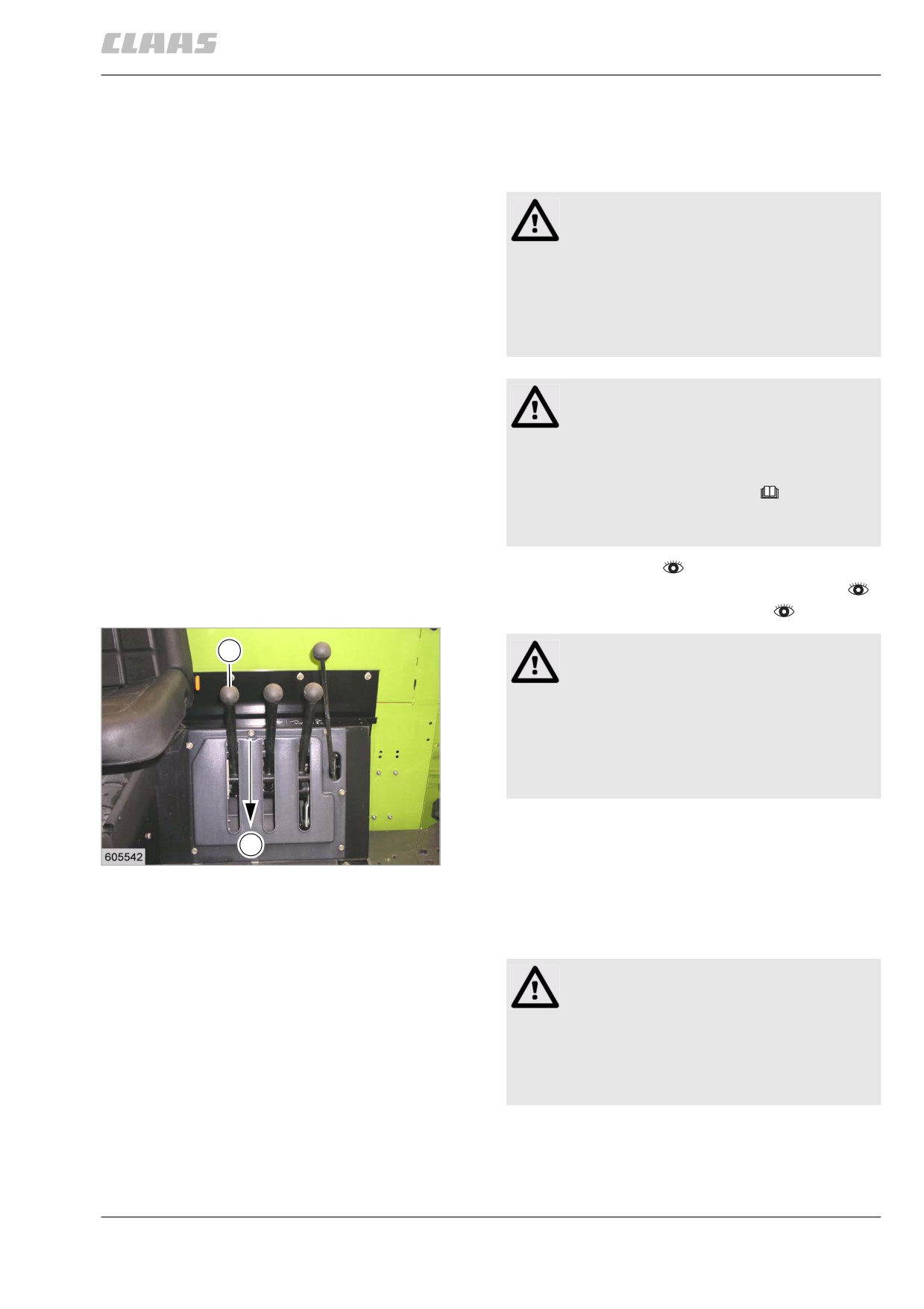
Engage front attachment.
B
- Push lever (1) slowly in direction (B) up to the
18
stop.
19419
The front attachment / feeder unit is engaged softly.
The lever (1) remains in the bottom position after
engaging.
Warning!
Incorrect diesel engine speed when driving in
the crop.
Machine damage.
- Set the diesel engine to max. no-load
speed before driving into the crop.
203
11 Fieldwork
11.5 Feeder unit
67087
83170
11.5.5 Disengaging the front attachment
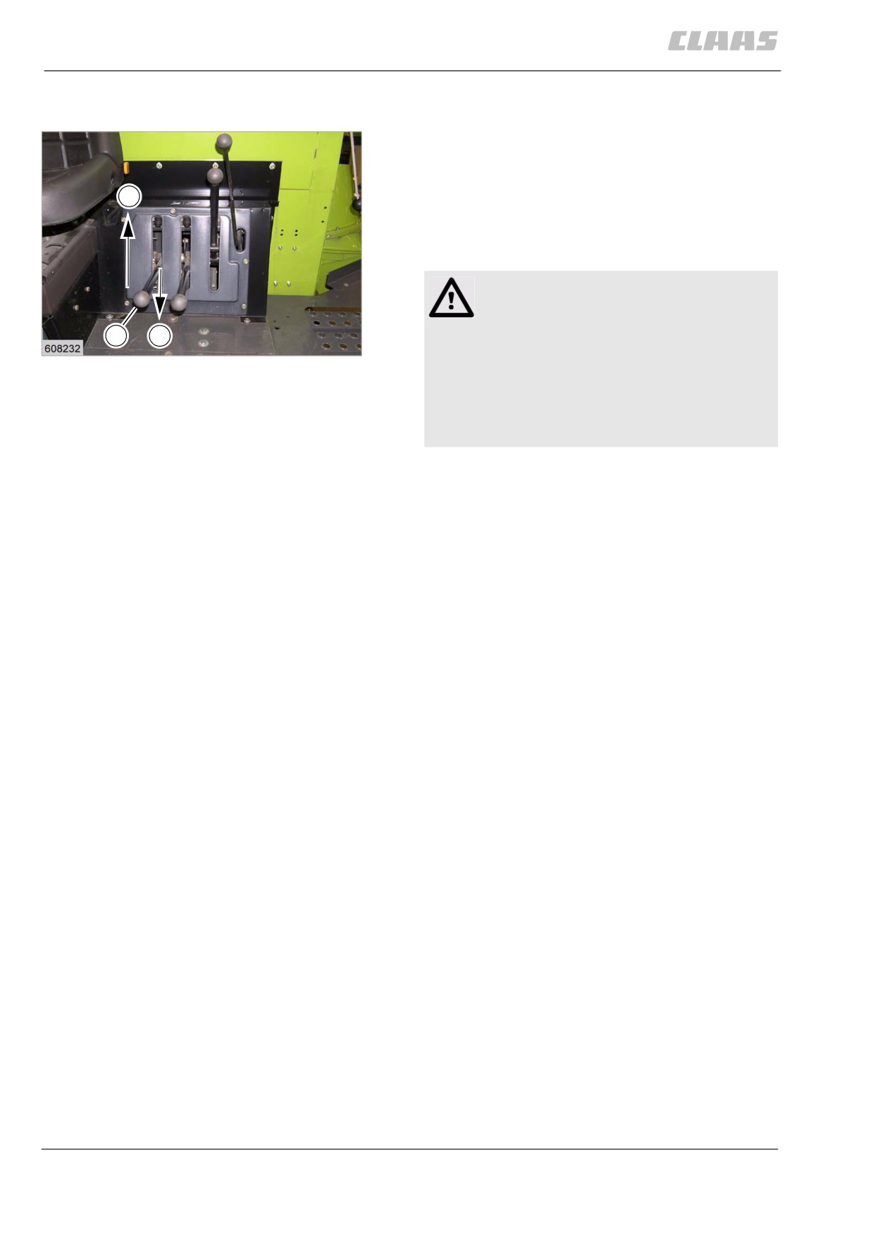
- Push lever (1) in direction (B) up to the stop.
Guide the lever upwards. The lever now automati-
cally remains
A
at the upper position (A).
The front attachment / feeder unit is disengaged and
runs on slightly.
Danger!
Machine components may run on although the
drive has been shut down.
1
B
19
Death or serious injury.
19605
- Never touch any machine parts that are
running on.
- Wait until all machine parts have stopped
moving.
204
11 Fieldwork
11.6 Threshing mechanism
67087
11.6 Threshing mechanism
82177
11.6.1 Engaging the threshing mechanism
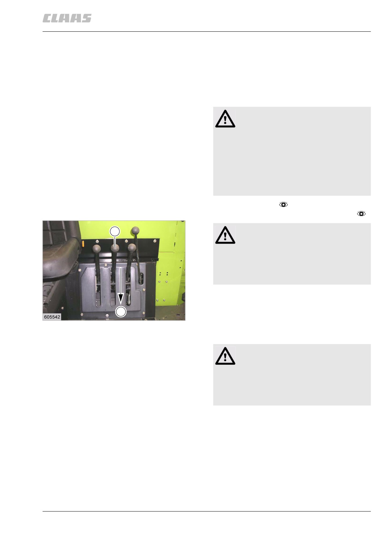
A spring-loaded jockey pulley tightens the threshing
mechanism drive V-belt against the pulleys and power
is transmitted from the engine output pulley to drive the
complete threshing mechanism.
Danger!
Engaging the threshing mechanism simulta-
neously engages the straw chopper, straw
spreader and chaff spreader.
Danger from thrown parts.
Death or serious injuries!
- Before starting the machine ensure that
there are no persons or objects in the
hazardous area.
- Prepare fieldwork.
- Set diesel engine speed to slow idling speed.
Warning!
1
High wear.
Machine damage.
- Engage / disengage the threshing mecha-
nism at slow idling speed of the diesel
engine.
- Engage the threshing mechanism.
- Push lever (1) slowly in direction (B) up to the
B
stop.
20
19419
The threshing mechanism is gently engaged. The
lever (1) remains in the bottom position after engaging.
Warning!
Incorrect diesel engine speed when driving in
the crop.
Machine damage.
- Set the diesel engine to max. no-load
speed before driving into the crop.
205
11 Fieldwork
11.6 Threshing mechanism
67087
82180
11.6.2 Disengaging the threshing mechanism
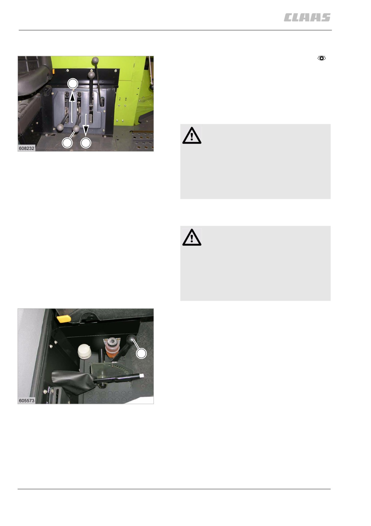
- Set diesel engine speed to slow idling speed.
- Push lever (1) in direction (B) up to the stop.
Guide the lever upwards. The lever now automati-
A
cally remains
at the upper position (A).
The threshing mechanism is disengaged and runs on
slightly.
Danger!
Machine components may run on although the
1
B
21
drive has been shut down.
19605
Death or serious injury.
- Never touch any machine parts that are
running on.
- Wait until all machine parts have stopped
moving.
86956
11.6.3 Adjusting the concave
Danger!
Unexpected machine movements.
Death or serious injuries!
- Never adjust the threshing concave dur-
ing threshing.
- Make sure that no more crop lies between
the threshing drum and threshing
concave.
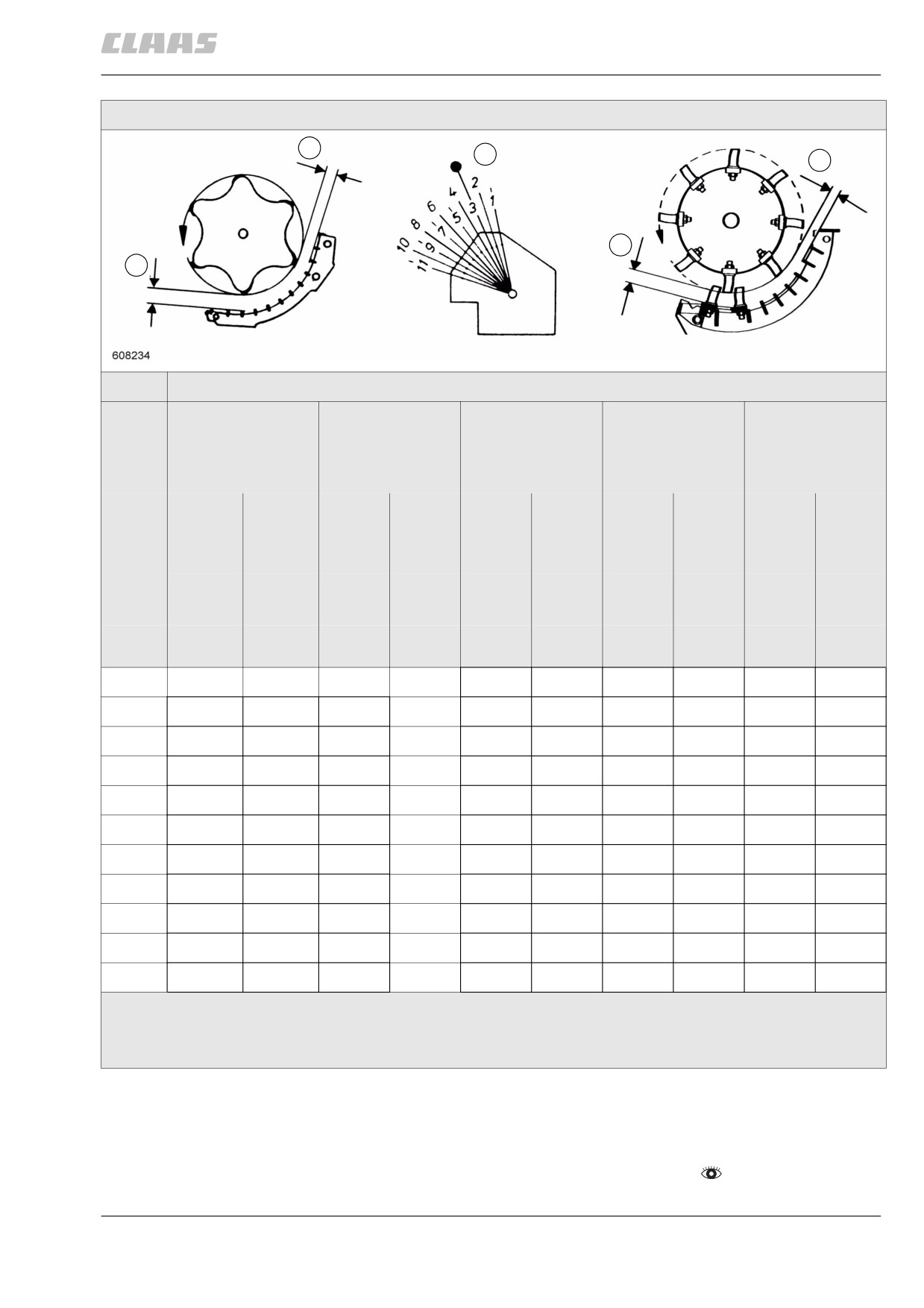
Using lever (H), the clearance between main concave
and threshing drum can be set simultaneously at the
concave entrance and the concave exit.
- Lever (H) down = increases concave distance.
- Lever (H) up = decreases concave distance.
H
22
19428
206
11 Fieldwork
11.6 Threshing mechanism
67087
Concave settings
B
H
B
A
A
Main concave
Wire N10 **
Wire N10
***
Wire N18 **
Sheet-metal
Spike tooth**
(19 x 40)***
Wire N12 **
Sheet-metal
(10 x 38)***
A
B
A
B
A
B
A
B
A
B
Meas-
3rd
10th
2nd
9th
3rd
2nd last
2nd
9th
1st
3rd last
ured at
**
**
con-
cave
2nd
9th
bar
***
***
Lever H
(mm)
(mm)
(mm)
(mm)
(mm)
(mm)
(mm)
(mm)
(mm)
(mm)
(hole)
1
10
1
10
2
24
9
19
4
14
7
2
11
2
11
4
26
10
21
5
15 *
8 *
3
13 *
3 *
13 *
5 *
28
11
23
7
17
9
4
15
4
15
6
30
12
25
9
19
11
5
17
6
17
8
33
14
27
11
21
13
6
19
8
19
10
35
16
29
13
23
15
7
21
10
21
12
37
18
31
15
25
17
8
23
12
23
14
40 *
20 *
33 *
17 *
27
19
9
25
14
25
16
42
22
35
19
29
21
10
28
16
28
18
44
24
37
21
31
23
11
30
18
30
20
47
26
40
24
33
26
** = Basic concave adjustment, ** = Continuous concave, *** = Multicrop concave with 3 concave
segments
A = Concave entrance, B = Concave exit
82336
11.6.4 Installing / removing the disawner bars
(accessory)
- Observe the general warnings at the beginning of
the "Fieldwork" chapter.
207
11 Fieldwork
11.6 Threshing mechanism
67087
Machine with multicrop wire concave
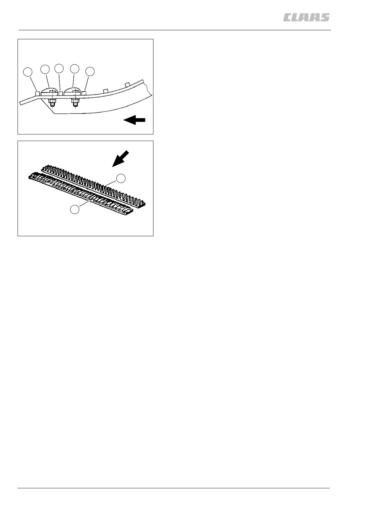
For better disawning, up to two three-piece disawner
bars can be installed in the main concave.
L
2.
R
1.
3.
One three-piece bar is installed ex works. Another
three-piece bar is enclosed with the machine.
- Remove the threshing concave segments.
- Bolt on the disawner bars using 8.5 x 40 x 3 wash-
ers and self-locking nut VM 8.
- Bolt on the left-ribbed disawner bar (L) between
the 1st and 2nd concave bars.
23
- Bolt on the right-ribbed disawner bar (R)
16380
between the 2nd and 3rd concave bars.
- Install the threshing concave segments.
R
L
24
16379
208

11 Fieldwork
11.6 Threshing mechanism
67087
Machine with standard wire concave
For better disawning, up to two one-piece disawner
R
bars can be installed in the main concave.
In the ex works condition, one one-piece bar with mat-
ing bar is provided. Another one-piece bar (R) with a
mating bar is enclosed with the machine. (accessory)
- When required, unscrew disawner bar (R) with
mating bar from the stone trap cover.
WARNING:
25
Dirty concave.
28507
Machine damage.
1.
L
2.
R
3.
- Make sure surroundings are clean.
- Clean concave prior to installation.
- Ensure that the disawner bars make con-
tact with the concave wires.
- Bolt down the disawner bars (L, R) using 6 hex.
5
5
bolts M 8 x 25 DIN 933-8.8, contact washers A 8
and mating bar (5) for each bar.
- Bolt on the left-ribbed disawner bar (L) between
F
the 1st and 2nd concave bars.
26
- Bolt on the right-ribbed disawner bar (R)
19614
between the 2nd and 3rd concave bars.
R
L
27
16379
82332
11.6.5 Unslugging the threshing drum
- Observe the general warnings at the beginning of
the "Fieldwork" chapter.
L
WARNING:
Sensitive components surrounding the chisel.
Machine damage.
- Make sure that the chisel does not dam-
age the lubricating line and the speed
sensor.
- Set the threshing concave downwards.
28
19612
- Remove safety device.
209
11 Fieldwork
11.6 Threshing mechanism
67087
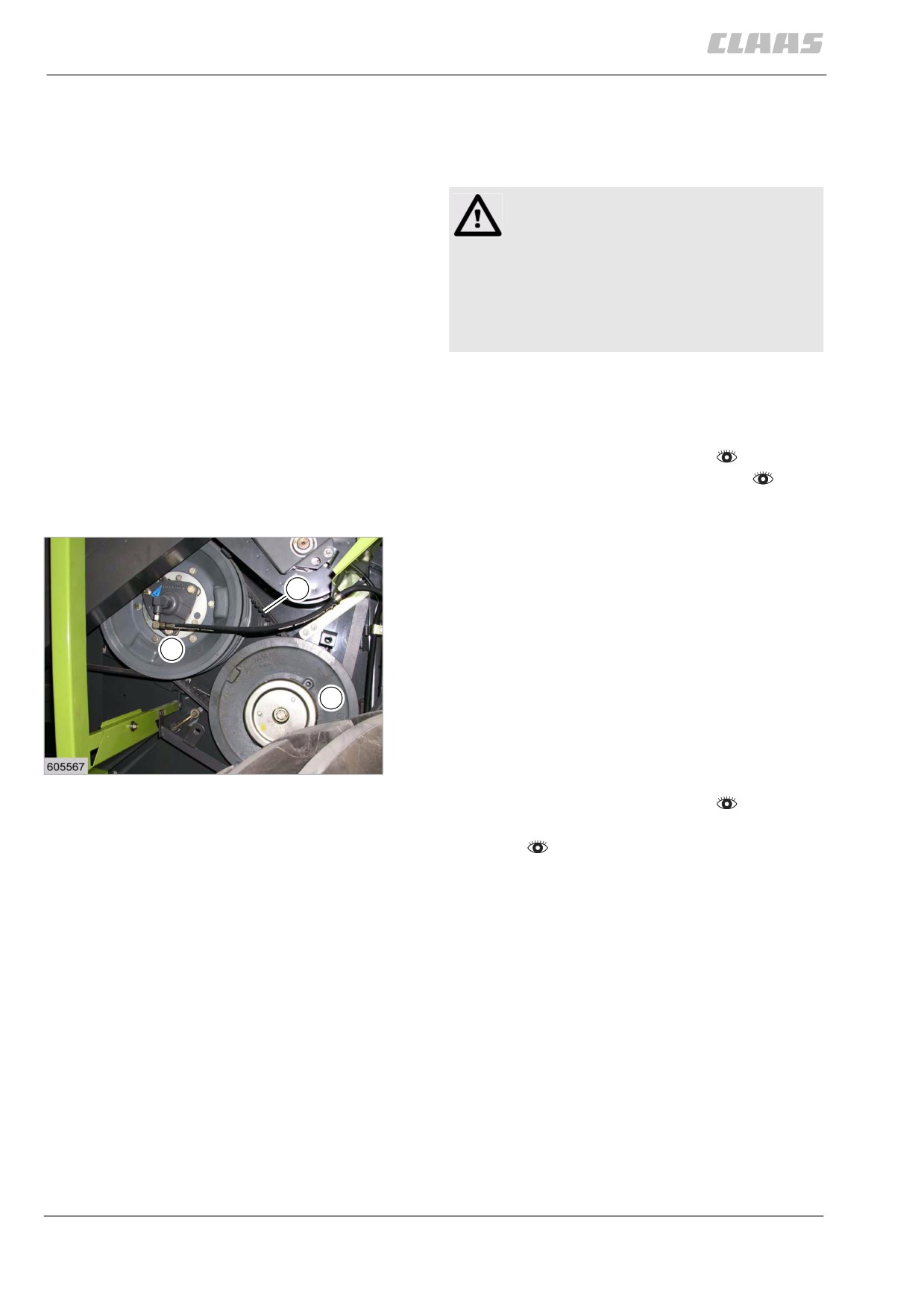
- Using a flat chisel (1) (part no. 00 0406 451 0)
over the segment with the threshing concave
open all the way, turn the threshing drum loose in
the direction opposite to the running direction.
Danger!
Moving machine parts and / or unexpected
motion of the machine.
Death or serious injuries!
- Make sure that the machine drives do not
inadvertently continue turning when
removing the straw plug.
- Remove the straw plug through the open drum
inspection cover.
- Close the drum inspection cover.
- Fit safety device.
- Engage the threshing mechanism.
- Set the concave to the desired position.
82247
11.6.6 Adjusting the threshing drum speed
Threshing drum variable-speed drive
The threshing drum speed can be infinitely varied from
2
650 to 1500 rpm by the threshing drum variable-speed
drive.
The speed variation combined with concave adjust-
1
ment allows quick adaptation of threshing operations
in order to match different crop conditions. Damp long-
strawed crops as well as crops difficult to thresh and
3
disawn require faster drum speeds than dry and brittle
crops.
The speed must be set depending on the crop. See
29
threshing chart.
19610
- Engage the threshing mechanism.
- Set the diesel engine speed to fast idling
speed.
210
11 Fieldwork
11.6 Threshing mechanism
67087
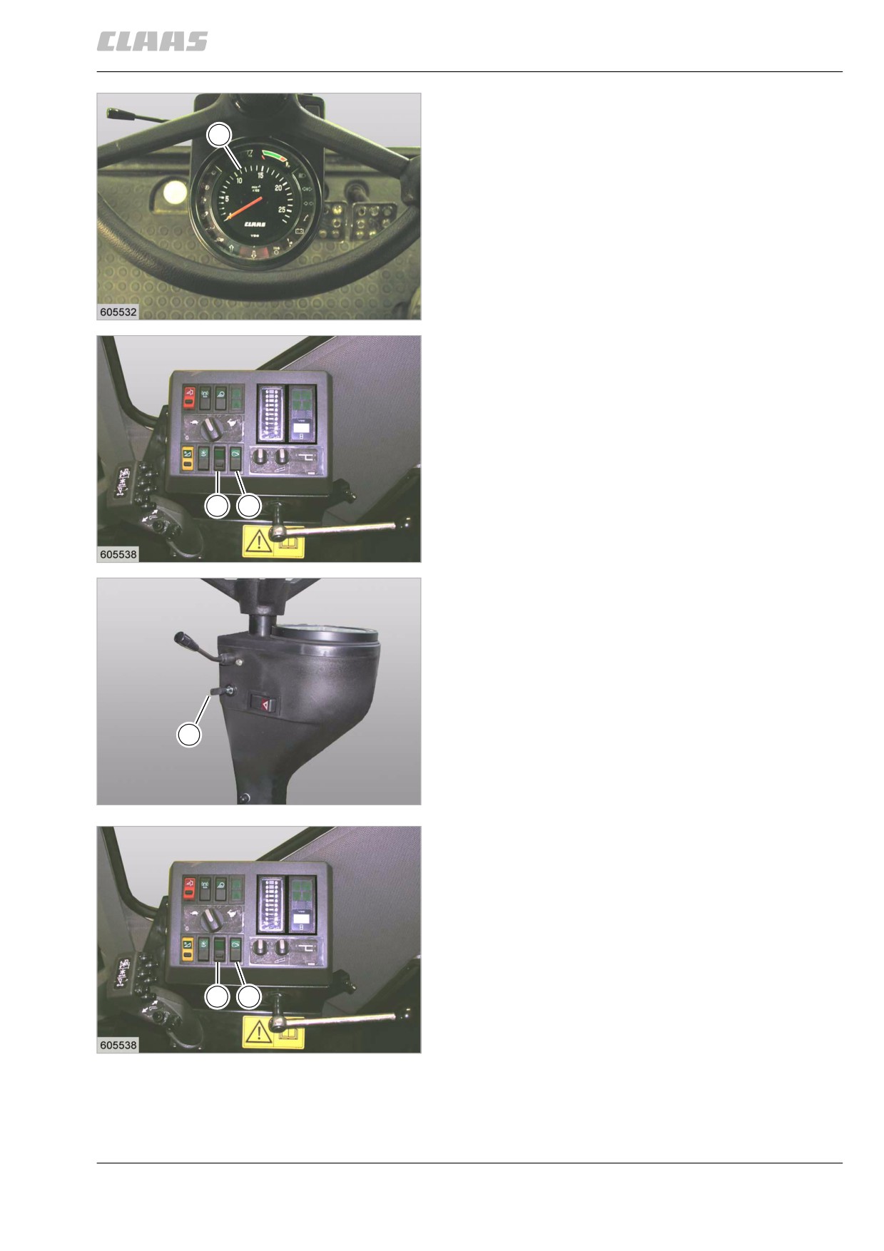
Reading the threshing drum speed on the vehicle
information unit (1)
1
DOMINATOR 150 / 140
- Unlock switch (4) with lock.
DOMINATOR 130
- Set switch (5) to the rear.
30
19367
4
3
31
DOMINATOR 150 / 140
19415
5
32
DOMINATOR 130
28458
Adjusting the threshing drum speed DOMINATOR
150 / 140
- Actuate switch (3) and reduce or increase thresh-
ing drum speed.
Blocking the speed adjustment
- Lock switch (4).
4
3
33
DOMINATOR 150 / 140
19415
211