CLAAS DOMINATOR 150 / 140 / 130. Operator’s Manual - page 12
10 Fieldwork settings
10.4 Separation
67086
10.4 Separation
82550
10.4.1 Adjusting the separation performance
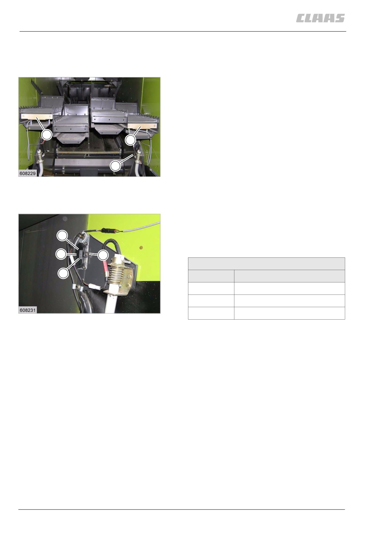
monitor sensors
The cleaning and separation performance monitor
allows the operator to make full use of the capacity of
the machine.
A gauge allows the operator to determine how fast the
machine can be driven without the reasonable grain
loss limit being exceeded.
2
Grains lost over the back of the combine with the straw
2
fall onto the sensors (2). The pulses generated are vis-
ualised by meter lights on a display.
The sensors (2) react with different sensitivities to dif-
4
ferent grain sizes and must therefore be calibrated to
12
the respective grain size, using switch (4).
19647
The gauge sensitivity setting is carried out during field-
work. See Adjusting the separation performance
monitor display.
- Adjust the sensitivity of the sensors to the different
grain sizes on switch (4).
1
The sensors react more / less sensitively, depending
on the pre-set grain size.
2
4
Sensitivity of sensors
3
Position
Grain sizes
1
for lightweight grains
2
for medium-weight grains
13
3
for heavy grains
19650
180
10 Fieldwork settings
10.5 Cleaning unit
67086
10.5 Cleaning unit
87656
10.5.1 Checking / adjusting the fan speed
display
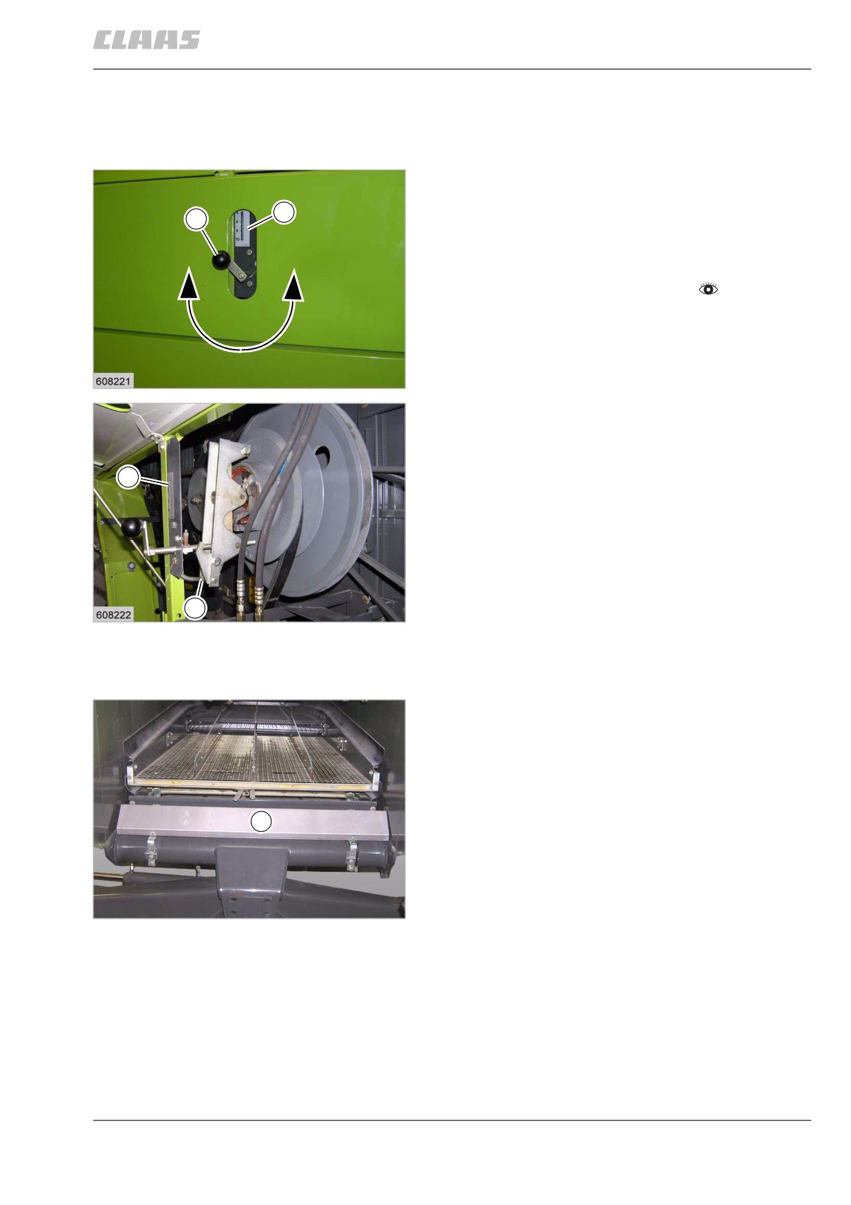
When delivered ex works, the fan speed display is acti-
vated. The display must be checked / pre-set as
S
required or after carrying out installation work on the
1
fan drive.
- Set fan speed to the lowest value with crank (1).
- Observe the general warnings at the beginning of
the "Fieldwork settings" chapter.
- Loosen clamp (3) and adjust plastic indicator rod
(2) so that the coloured ring is on the lowest
number of indicator scale (4).
14
19634
2
3
15
19635
82695
10.5.2 Adjusting the cleaning performance
monitor sensors
The cleaning and separation performance monitor
allows the operator to make full use of the capacity of
the machine.
A display allows the operator to determine how fast the
machine can be driven without the reasonable grain
loss limit being exceeded.
2
The grains carried beyond the sieve pan fall onto the
sensor (2). The pulses generated are visualised by
meter lights on a display.
The sensor (2) reacts with different sensitivities to dif-
ferent grain sizes and must therefore be calibrated to
16
the respective grain size, using switch (4).
19648
The sensitivity setting of the display is carried out while
fieldwork is in progress. See Adjusting the cleaning
performance monitor display.
181
10 Fieldwork settings
10.5 Cleaning unit
67086
- Adjust the sensitivity of the sensors to the different
grain sizes on switch (4).
The sensors react more / less sensitively, depending
on the pre-set grain size.
4
Sensitivity of sensors
Position
Grain sizes
1
2
1
for lightweight grains
3
2
for medium-weight grains
17
3
for heavy grains
10789
82957
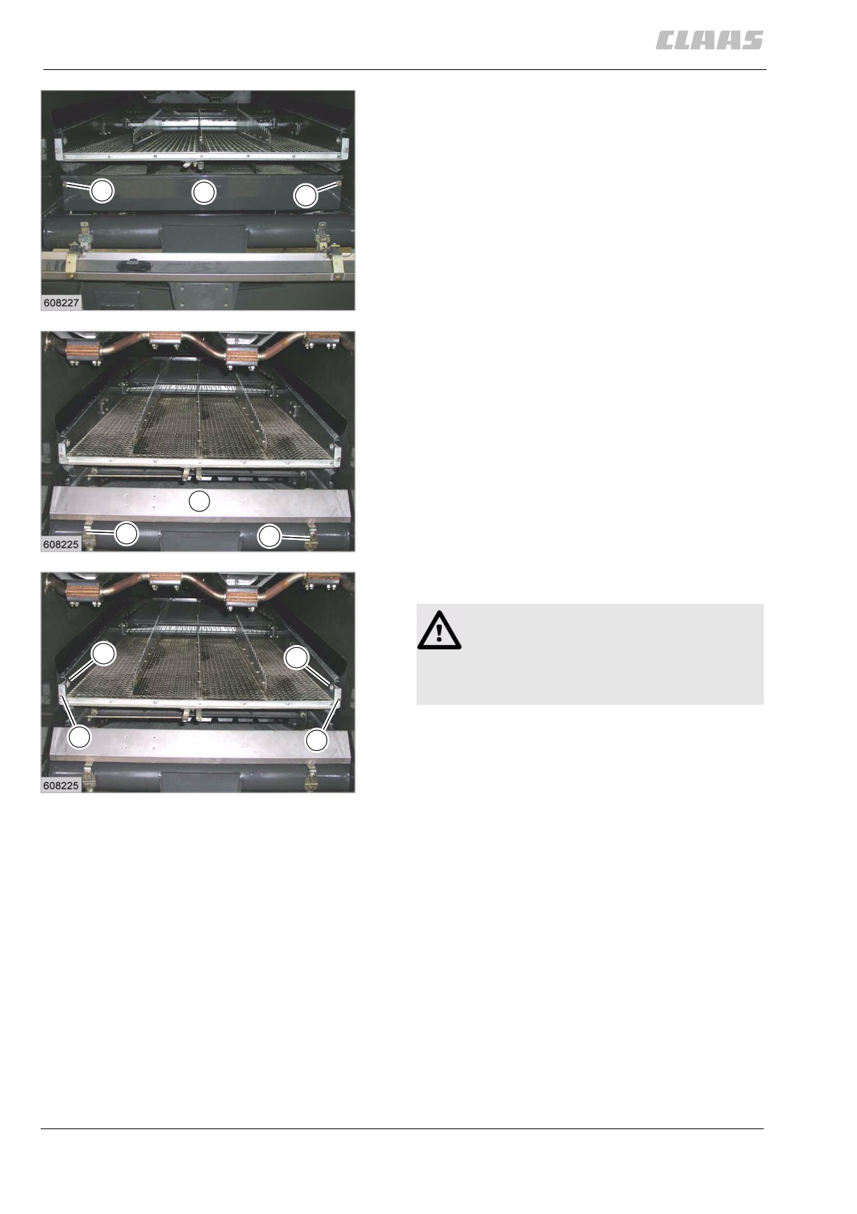
10.5.3 Removing the sieves
The sieves must / can be installed / removed as a
function of the crop to be harvested. See threshing
chart, see sieve chart.
The sieves can be removed / installed independently
of one another.
The straw chopper can be shifted to the rear as far as
possible. In this installation position, the sieves can be
mounted.
See straw chopper sieves installation position.
- Observe the general warnings at the beginning of
the "Fieldwork settings" chapter.
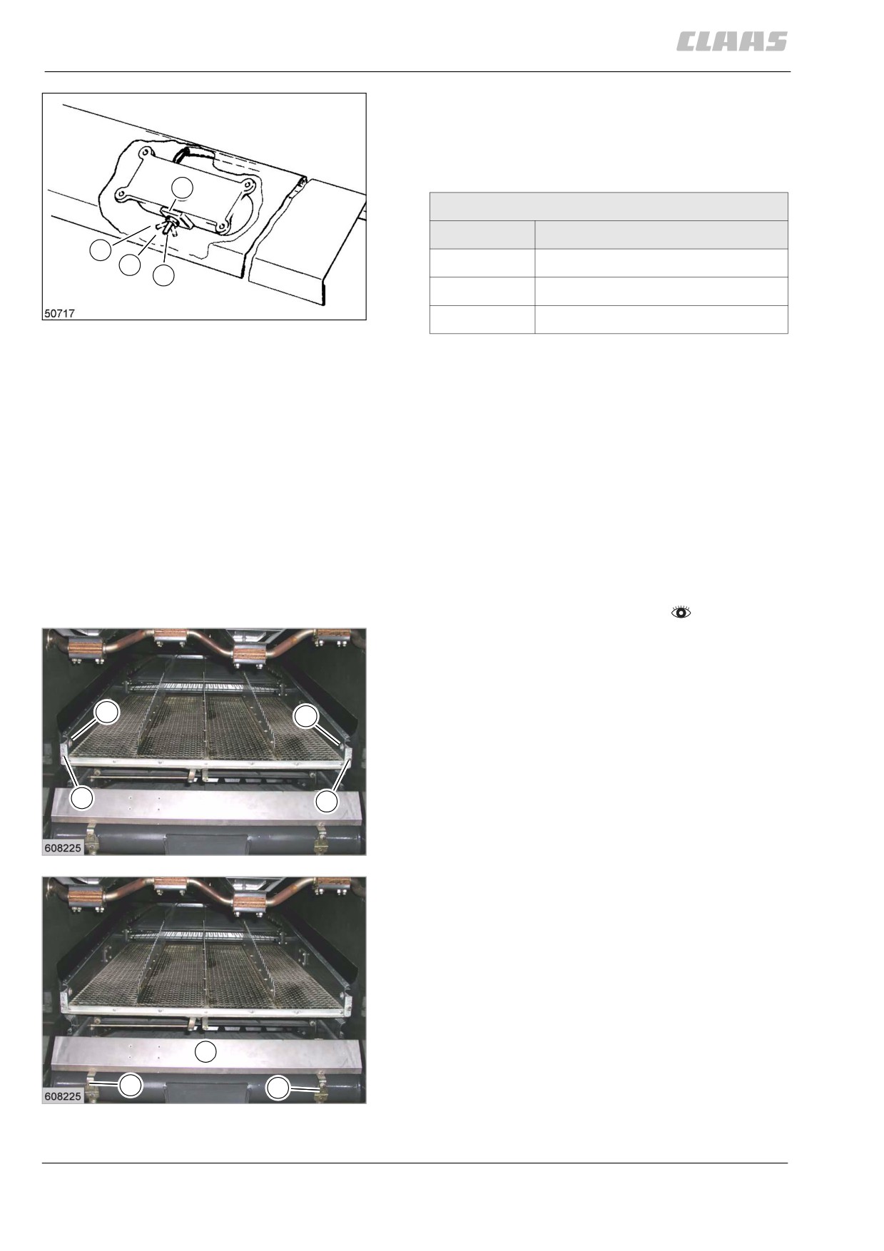
Removing the upper sieves
- Unscrew bolts (1).
- Remove bolts (2).
- Pull out the upper sieve to the rear.
2
2
1
1
18
19638
Removing the lower sieves
(machines with performance monitor)
- Unscrew bolts (1).
– Fold sensor (2) down.
2
1
1
19
19638
182
10 Fieldwork settings
10.5 Cleaning unit
67086
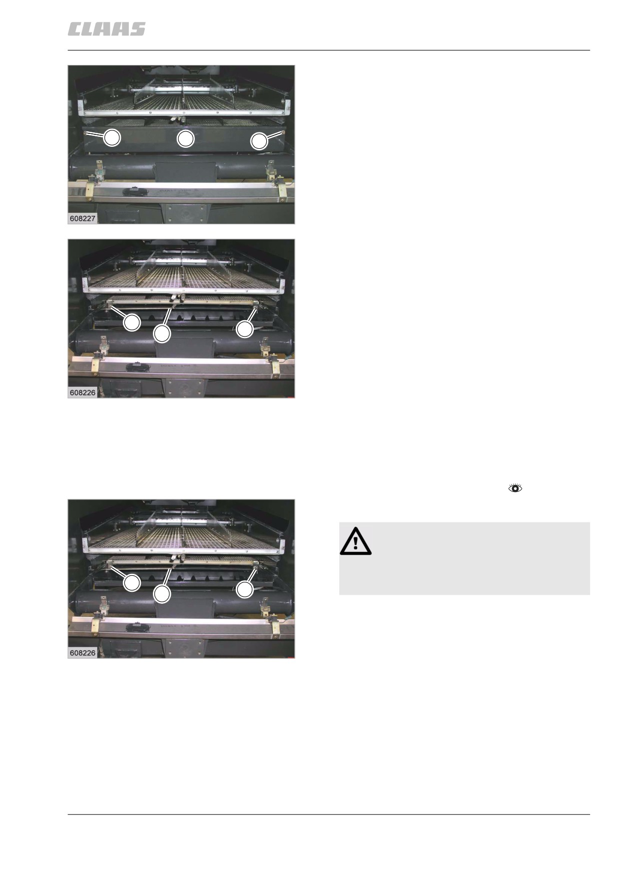
- Unscrew bolts (3) and remove cover (4).
3
4
3
20
19640
- Pull out cotter pin (5) at the linkage.
- Unscrew bolts (6).
- Pull out the lower sieve to the rear.
6
6
5
21
19641
82982
10.5.4 Installing the sieves
The sieves can be removed / installed independently
of one another.
- Observe the general warnings at the beginning of
the "Fieldwork settings" chapter.
Installing the lower sieves
WARNING:
Dirt in the guide rails.
Heavy action.
6
- Clean guide rails.
6
5
- Install lower sieve.
- Install linkage and secure with cotter pin (5).
- Arrest lower sieves with clamps and bolt down
22
hand-tight with bolts (6).
19641
183
10 Fieldwork settings
10.5 Cleaning unit
67086
- Install cover (4) and bolt down with bolts (3).
3
4
3
23
19640
(machines with performance monitor)
- Fold sensor (2) upwards.
- Screw down bolts (1).
2
1
1
24
19638
Installing the upper sieves
WARNING:
Dirt in the guide rails.
2
2
Heavy action.
- Clean guide rails.
- Install upper sieve.
1
1
- Mount bolts (1).
Tightening torque = 30 Nm
25
- Mount bolts (2).
19638
Tightening torque = 48.5 Nm
When installation of sieves is complete, the straw
chopper must be moved back to its initial position at
the front (putting the straw chopper out of operation).
184
10 Fieldwork settings
10.6 Crop receptacle / straw receptacle
67086
10.6 Crop receptacle / straw receptacle
83761
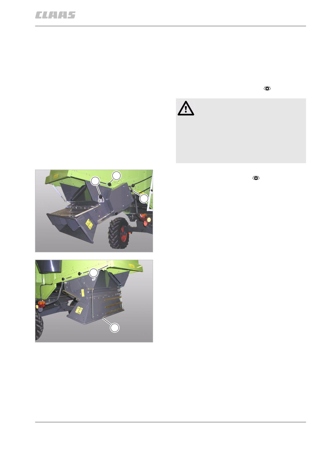
10.6.1 Removing the straw guide plate
(straw chopper with standard spreader)
To provide better access to the cutting cylinder, the
straw guide plate must be removed / folded down.
- Observe the general warnings at the beginning of
the "Fieldwork settings" chapter.
Danger!
The cutting cylinders of the straw chopper can
run on even if the drive is switched off.
Death or serious injuries!
- Never touch any machine parts that con-
tinue running.
- Wait until all machine parts have com-
pletely stopped moving.
The straw chopper is in the front position (putting the
12
straw chopper out of operation).
13
- Unscrew the turn lock (13).
12
26
28748
- Unhinge connecting rod at position (A).
- Swivel standard spreader (9) downwards.
A
9
27
28802
185
10 Fieldwork settings
10.6 Crop receptacle / straw receptacle
67086
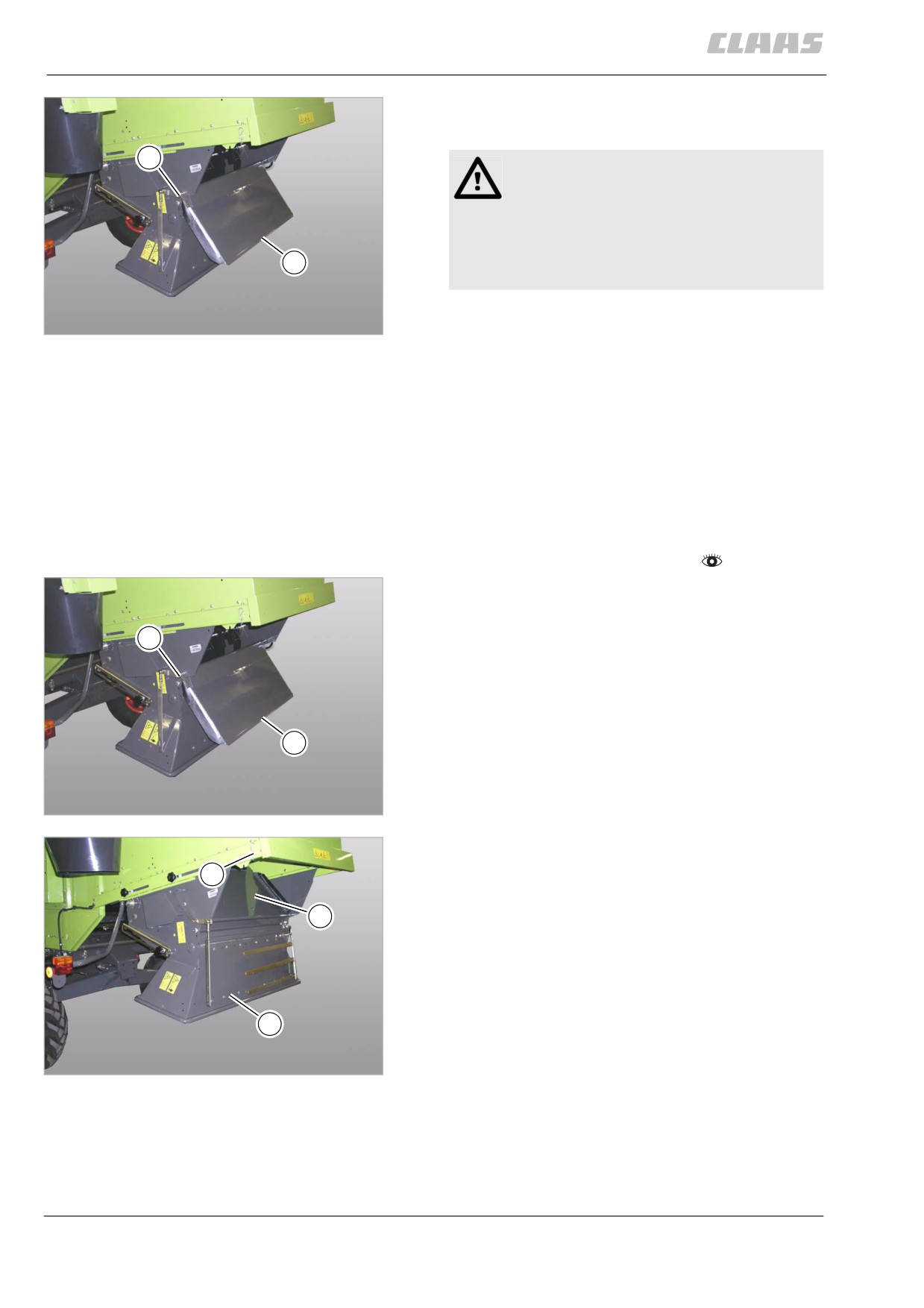
- Slacken off bolt (21) and swivel straw guide
plate (15) downwards.
21
Danger!
Risk of injury from sharp knives.
- Always wear gloves to avoid injuries
when removing and installing the knives.
- Arrest the cutting cylinder so it will not
15
rotate.
The free-swinging knives can now be fitted.
28
28806
When the straw guide plate is to be removed com-
pletely, the following steps must be carried out.
(2 persons are required)
- Back up straw guide plate (15) and slacken off
bolt (21) on both sides.
- Remove straw guide plate to the rear.
83763
10.6.2 Installing the straw guide plate
(straw chopper with standard spreader)
- Observe the general warnings at the beginning of
the "Fieldwork settings" chapter.
When installing the completely removed straw guide
plate, the following steps must be carried out.
(2 persons are required)
21
- Bolt down straw guide plate (15) with bolts (21) on
both sides.
15
29
28806
(1 persons are required)
A
- Swivel straw guide plate (15) upwards.
- Fit connecting rod at position (A).
15
- Swivel the standard spreader (9) to the desired
position.
9
30
28802
186
10 Fieldwork settings
10.6 Crop receptacle / straw receptacle
67086
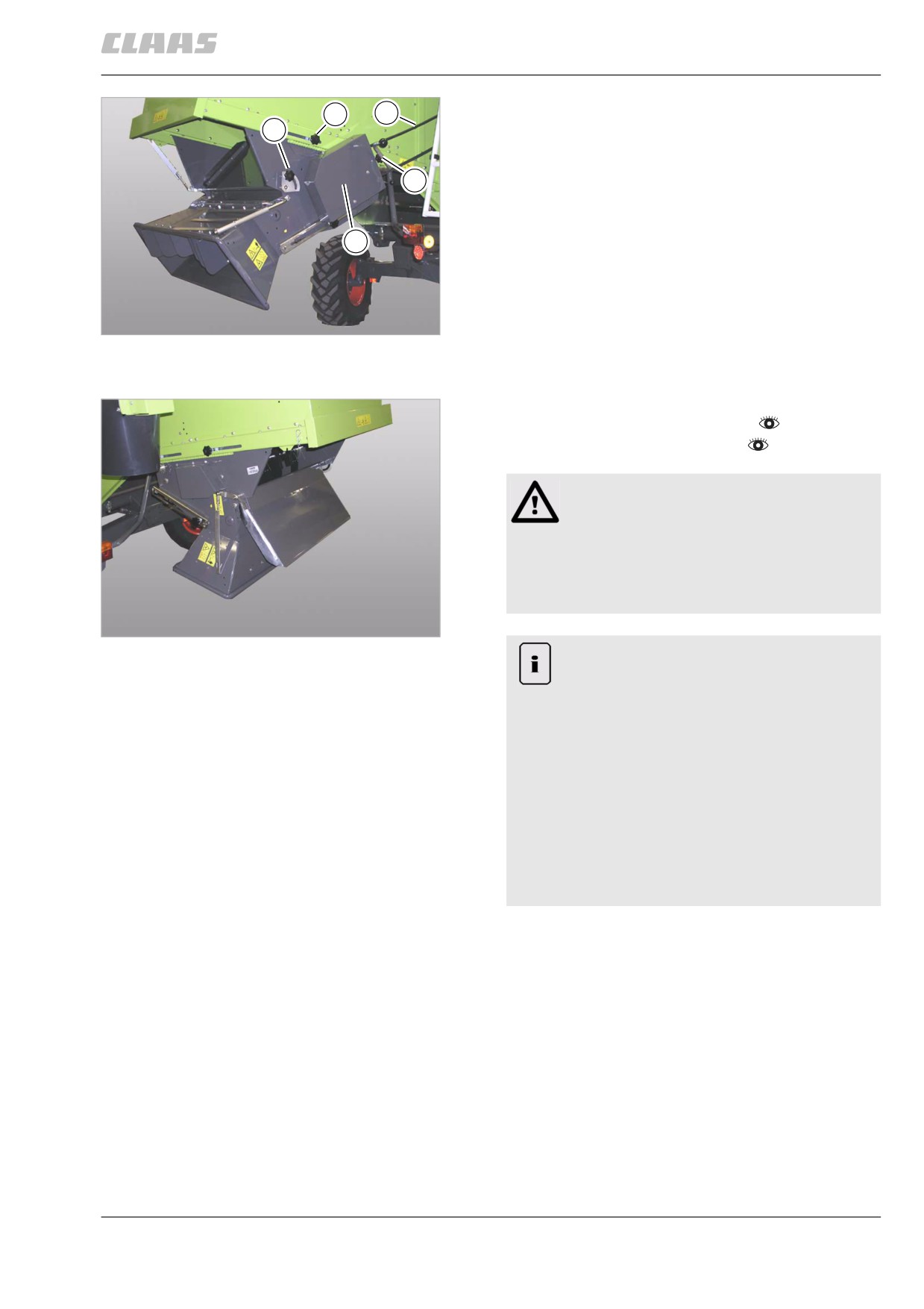
- Tighten the turn lock (13).
12
5
13
12
19
31
28748
83470
10.6.3 Unscrewing the free-swinging knives
-
Observe the general warnings at the beginning of
the "Fieldwork settings" chapter.
-
Remove the straw guide plate.
Danger!
Risk of injury from sharp knives.
- Always wear gloves to avoid injuries
when removing and installing the knives.
- Arrest the cutting cylinder so it will not
rotate.
32
28806
Note!
Uneconomic use of machine.
Increased fuel consumption.
Machine damage.
- Turn knives that are worn on one side.
When changing worn knives, replace the
opposite knife as well.Failure to observe
the above may result in unbalance of the
cutting cylinder - Consequential
damage!
- Operate the cutting cylinder only with the
complete number of knives.
-
Unscrew the free-swinging knives.
187
10 Fieldwork settings
10.6 Crop receptacle / straw receptacle
67086
83409
10.6.4 Bolting down the free-swinging knives
-
Observe the general warnings at the beginning of
the "Fieldwork settings" chapter.
Danger!
Risk of injury from sharp knives.
- Always wear gloves to avoid injuries
when removing and installing the knives.
- Arrest the cutting cylinder so it will not
rotate.
33
Danger!
28806
Use of unauthorised spare parts.
Death or severe injuries, machine damage.
- Use genuine CLAAS spare parts.
Note!
Uneconomic use of machine.
Machine damage.
- The knives must not jam, but must move
freely.
- Operate the cutting cylinder only with a
complete set of knives in each case.
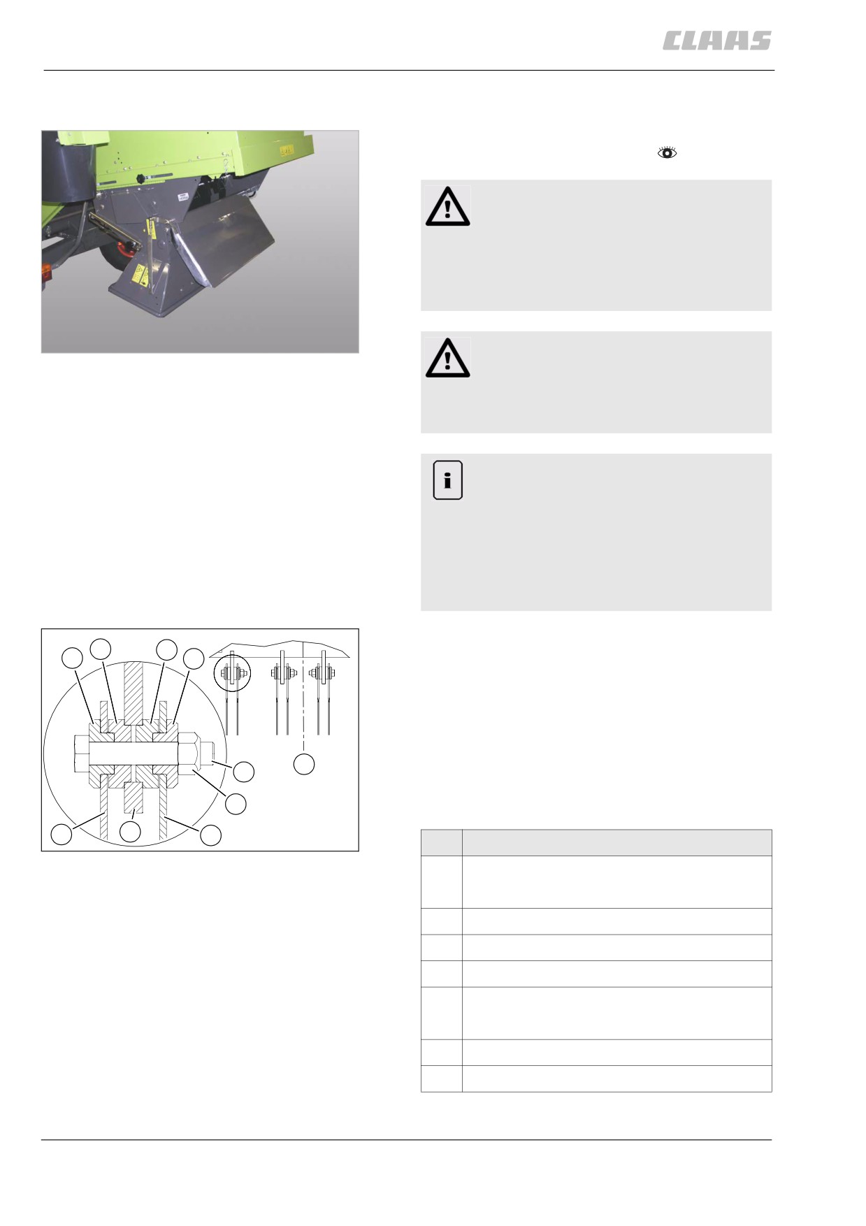
Bolt on free-swinging knives for grain:
4
4
2
2
- Two free-swinging knives (grain) must be bolted to
each mounting plate (H) as shown in figure.
- Mount hex. bolts (1) from the outside to the inside,
facing the machine centre (M).
Tightening torque:
Bolts with Dacromet coating
M
1
M 10 - 10.9 = 55 Nm
5
Observe decal on the cutting cylinder!
3
H
3
34
Designation
28775
1
Hex. bolt
ISO 4014 - M 10 x 55 -10.9
2
Bushing D 30 x 10
3
Free-swinging knife (grain)
4
Bushing D 30 x 11
5
Self-locking nut
ISO 7042 VM 10 -10
H
Mounting plate
M
Machine centre
- Install the straw guide plate.
188
10 Fieldwork settings
10.6 Crop receptacle / straw receptacle
67086
83338
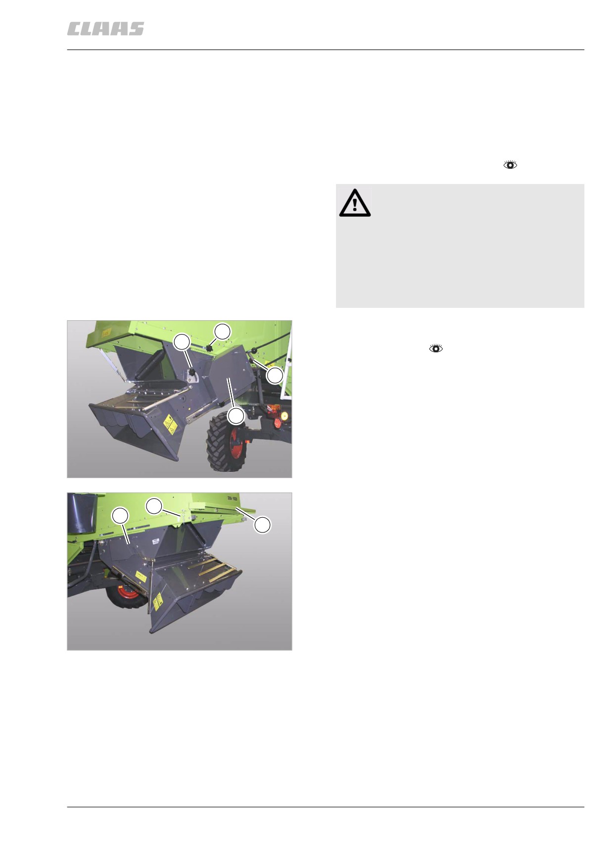
10.6.5 Straw chopper sieves installation
position
The straw chopper can be shifted to the rear as far as
possible. In this installation position, the sieves can be
mounted.
- Observe the general warnings at the beginning of
the "Fieldwork settings" chapter.
Danger!
The cutting cylinders of the straw chopper can
run on even if the drive is switched off.
Death or serious injuries!
- Never touch any machine parts that con-
tinue running.
- Wait until all machine parts have com-
pletely stopped moving.
- Move the straw chopper from the front
12
position (putting the straw chopper out of opera-
13
tion) to the rear.
- Unscrew turn locks (12) on both sides.
12
- Unscrew the turn lock (13).
- Unscrew guard (19) and remove belt.
19
35
28748
- Unhinge connecting rod at position (A).
A
- Disconnect speed monitoring cable at
B
20
position (B).
- Fold up panel (20) and support it.
36
28800
189
10 Fieldwork settings
10.6 Crop receptacle / straw receptacle
67086
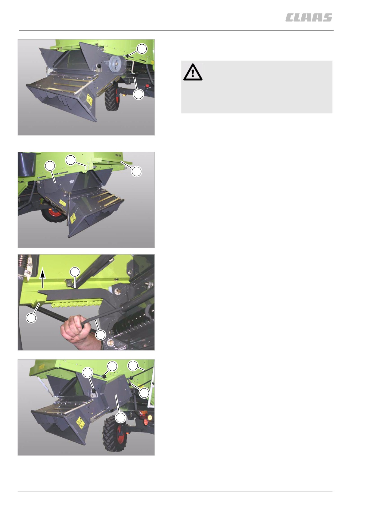
- Move the straw chopper to the rear as far as pos-
12
sible, using crank (14).
Danger!
Pinch point from moving machine parts.
Serious injuries.
14
- Secure machine parts.
- Comply with instructions.
- Bolt down turn lock (12), thus securing the straw
chopper against sliding to the front.
37
28801
The sieves can now be installed.
When installation of sieves is complete, the straw
A
chopper must be moved back to its initial position at
B
the front (putting the straw chopper out of operation).
20
- Move the straw chopper fully to the front, using
the crank.
- Use lever (17) for lifting support (16) over the
keeper (18).
- Unlock panel (20) and fold it down.
- Connect speed monitoring cable at position (B).
- Fit connecting rod at position (A).
38
28800
16
18
17
39
28710
- Install belt (5) and bolt down guard (19).
12
5
- Bolt down turn locks (12) on both sides.
13
- Tighten the turn lock (13).
- Check belt (5). The belt (5) must make contact
12
with all pulleys, jockey pulleys and guide rollers.
Provide contact of belt if required.
– Close the right side cover.
19
40
28748
190
10 Fieldwork settings
10.7 Grain delivery
67086
10.7 Grain delivery
83157
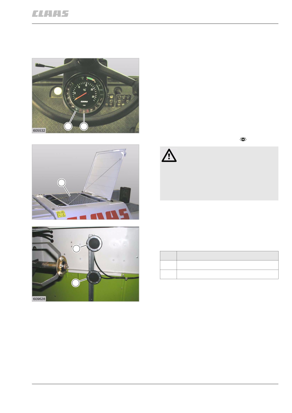
10.7.1 Adjusting the grain tank full indicator
DOMINATOR 150
The grain tank full indicator indicates the 70% grain
tank filling level by means of indicator light (3) and the
100% grain tank filling level by indicator light (4) on the
vehicle information unit.
The grain tank fill indicator (1 and 2) levels can be
staggered, so that depending on the tank unloading
possibility the time span between the illumination of
the window and the tank unloading can be individually
utilised.
Big windows also allow the grain tank level to be
checked from the operator's platform.
3
4
41
-
Observe the general warnings at the beginning of
19367
the "Fieldwork settings" chapter.
Danger!
Danger of falling!
Death or serious injuries!
- Arrange for additional safety precautions.
1
- Only enter areas protected by railings.
- Areas originally without railings must be
protected by additional railings.
-
Open the grain tank cover and fold it open to the
rear as far as possible.
42
-
Remove guard (1).
30205
-
Unscrew grain tank fill indicator.
–
Set height of grain tank fill indicator.
-
Bolt on grain tank fill indicator.
2
Designation
1
70 % grain tank filling
2
100 % grain tank filling
1
43
19662
191

10 Fieldwork settings
10.7 Grain delivery
67086
- Fit guard (1).
- Remove additional safety precautions.
1
44
30205
192
11 Fieldwork
11.1 General Information
67087
11 Fieldwork
11.1 General Information
85060
11.1.1 General warnings Fieldwork
In the following sections of this chapter, a procedure
instruction refers to the following general warnings.
Danger!
Always stop the engine before carrying out
any work on the machine.
Moving machine parts and / or unexpected
machine movement.
Death or serious injury.
- Diesel engine OFF.
- Apply parking brake.
- Remove the ignition key.
- Remove key of battery isolating
switch.
- Wait for machine parts which run on have
come to a complete halt.
- Secure machine by wheel chocks.
- Ensure that the machine cannot be
started by any third persons.
Danger!
The front attachment, reel and feeder unit may
drop uncontrolled.
Death or serious injuries!
- Apply safety locks.
- Keep a safe distance from the hazard
area.
193
11 Fieldwork
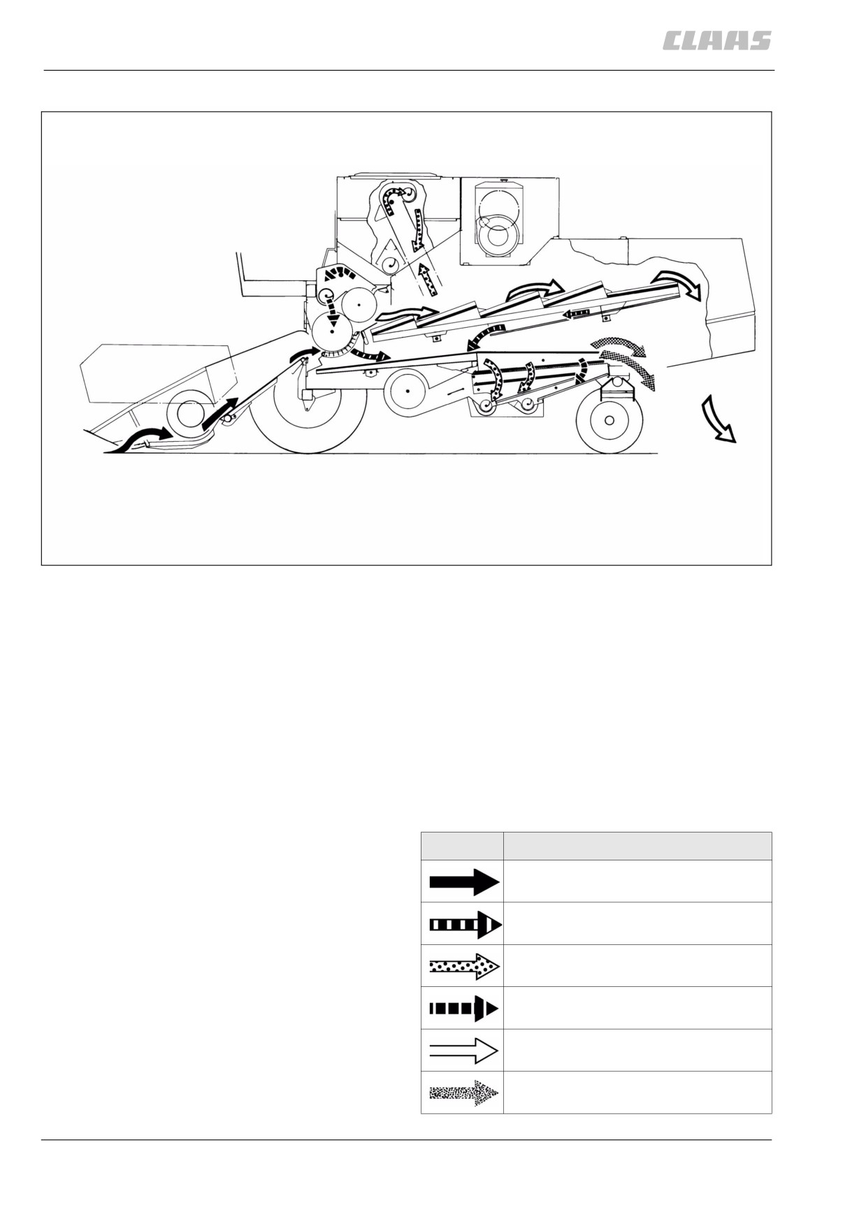
11.2 Description and function
67087
11.2 Description and function
19320
1
69387
11.2.1 Cutterbar
Dividers separate the standing grain from the grain
which is to be cut.
Grain lifters lift lodged crops and avoid cutting losses in
crops with hanging heads.
The reel moves the cut crop to the intake auger. The
auger flights move the material to the cutterbar centre
where the feed rake delivers it to the drum for thresh-
ing. The stone trap collects solid objects brought up by
the feed rake, thus preventing damage to the threshing
parts.
Designation
Grain
Grain, chaff, broken straw
Grain
Returns
Straw
Chaff
194
11 Fieldwork
11.2 Description and function
67087
69373
11.2.2 Threshing mechanism
Threshing is performed by drum and concave. The
bulk of the grain together with the chaff and broken
straw passes through the concave onto the prepara-
tion floor of the sieve pan. The impeller delivers the
straw and remainder of the grain to the straw walkers.
A deflector curtain behind the impeller holds back
bouncing grains and deflects them down onto the front
of the straw walkers.
69375
11.2.3 Straw walker
The straw walkers separate the remainder of the grain
from the straw. The straw is either removed out of the
combine through the rear panel or undergoes further
processing by special attachments (e. g. straw chop-
per). The grains separated by the straw walkers are
returned to the sieve pan via the under-walker return
floor. Crankshafts with agitator tines intensify the loos-
ening of the straw on the straw walkers.
69377
11.2.4 Cleaning unit
Grain mixed with chaff and broken straw is fluffed by
means of the shaking action of the preparation floor
and at the same time moved onto the sieves.
The wind blast of the cleaning fan blows the light parti-
cles (chaff) to the rear, out of the machine. The grain
falls through the upper and lower sieve into the clean
grain auger trough and is conveyed into the grain tank
by the clean grain elevator. All parts heavier than chaff
and bigger than grain travel over the upper sieve and
lower sieve, drop into the returns auger and are moved
to the returns elevator. The elevator carries the returns
to the drum for further threshing. Swinging the grain
tank unloading tube into operating position allows the
grain tank to be quickly emptied into a truck or trailer
alongside the combine.
69380
11.2.5 Disawning
When combining grain which is unusually hard to dis-
awn or in which it is hard to separate the seeds from
the heads or husks, additional disawning plates can be
installed in the concave.
195