CLAAS DOMINATOR 150 / 140 / 130. Operator’s Manual - page 11
9 Driving and transportation
9.6 Hitch
67085
Danger!
Lock not engaged.
Trailer releases from the towing vehicle.
1
Death or serious injuries!
- Ensure that the lock is securely engaged.
- Never pull a trailer with the lock
disengaged.
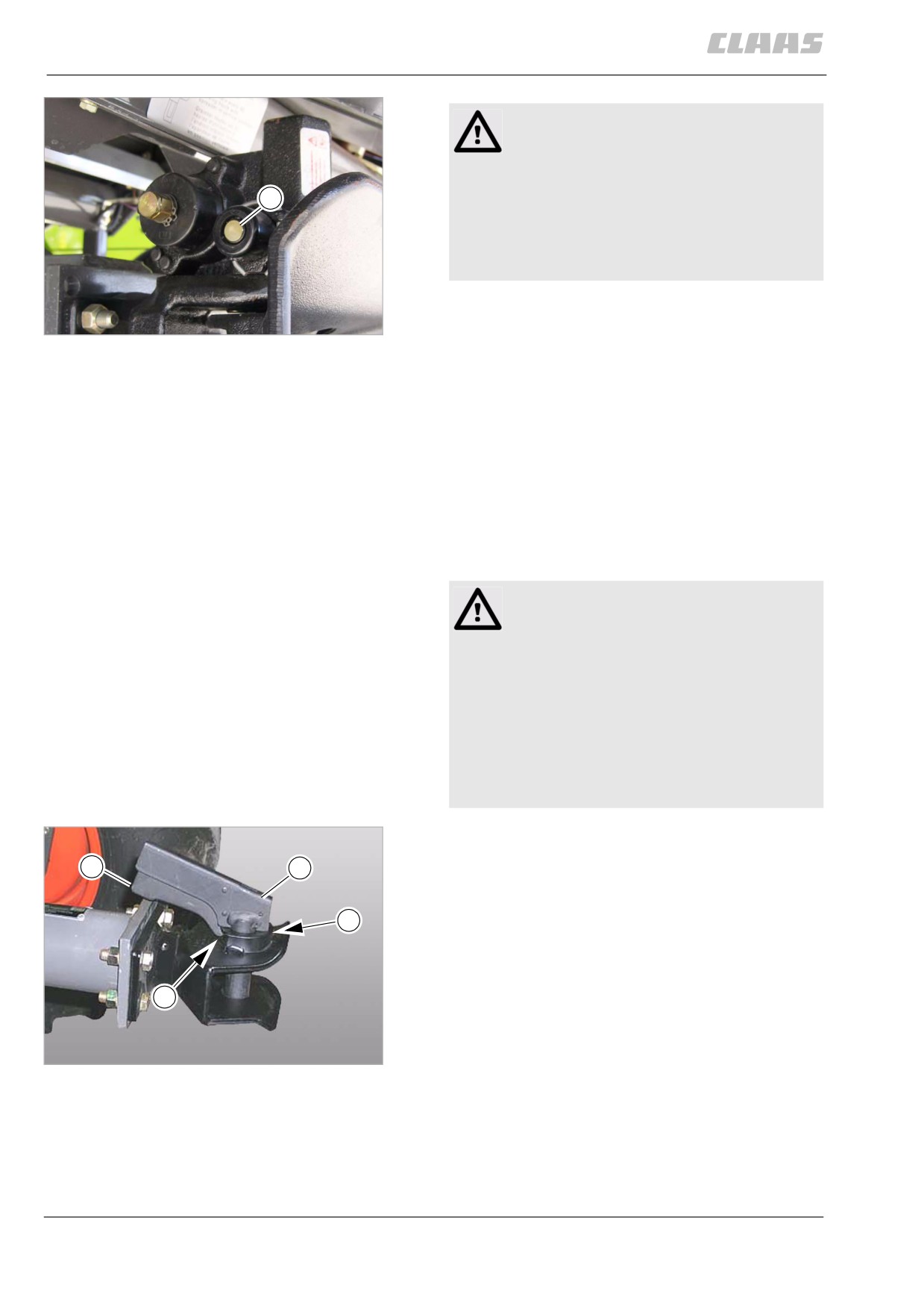
- Ensure that the pin (1) is introduced into the hous-
ing until the end of pin (1) is flush with it.
50
Trailer hitch type 841 ...
18966
- Raise the trailer support wheel.
- Connect the power supply plug.
- If present, connect the breakaway cord to the
trailer hitch.
- Check the trailer lighting.
- If there is a braking system, carry out a brake test.
81911
9.6.2 Unhitching the trailer
- Identify the trailer hitch by means of the identifica-
tion plate on the trailer hitch.
Observe the type-specific details.
Danger
Limbs within range of the trailer hitch or the
trailer.
Risk of death or serious injuries.
- Keep limbs away from the trailer hitch.
- Never remain standing between the trailer
hitch and the trailer.
- Observe the regulations of the German
employers' liability insurance association
or its equivalent.
Type AK 64/1 B ...
- Disconnect the power supply plug.
4
5
- If present, disconnect the breakaway cord from
the trailer hitch.
6
- Secure the rear axle of the transport carriage so it
will not roll away.
- If installed, swing out the trailer gauge wheel.
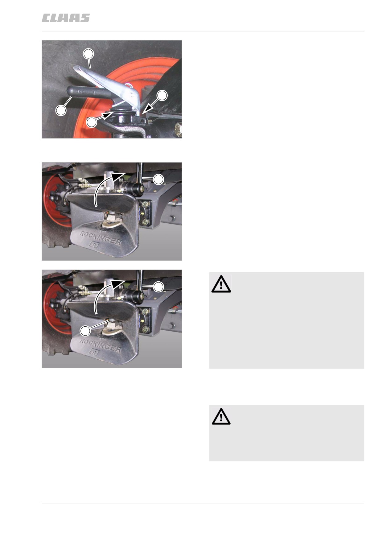
- Press pawl (4) and handle of pin (5) together and
7
pull pin (5) out of the trailer hitch.
- Slowly drive the tractor forward.
- Press pawl (4) and handle of pin (5) together and
51
plug pin (5) into the trailer hitch up to the stop (6).
Trailer hitch type AK 64/1 B ...
30204
- Release the pawl (4) and ensure that lock (7) has
engaged at the trailer hitch.
164
9 Driving and transportation
9.6 Hitch
67085
Type 810 ...
4
- Disconnect the power supply plug.
- If present, disconnect the breakaway cord from
the trailer hitch.
- Secure the rear axle of the transport carriage so it
will not roll away.
7
- If installed, swing out the trailer gauge wheel.
- Push down pawl (4) and pull pin (5) out of the
5
trailer hitch.
6
- Slowly drive the tractor forward.
- Push down pawl (4) and push pin (5) into the
52
trailer hitch up to the stop (6).
Trailer hitch type 810 ...
20717
- Release the pawl (4) and ensure that lock (7) has
engaged at the trailer hitch.
Type 841 ...
-
Disconnect the power supply plug.
1
–
If present, disconnect the breakaway cord from
the trailer hitch.
-
Secure the rear axle of the transport carriage so it
will not roll away.
-
If installed, swing out the trailer gauge wheel.
–
Push lever (1) upwards until it catches.
–
Slowly drive the tractor forward.
53
Trailer hitch type 841 ...
19009
Danger!
1
Locking the trailer hitch by hand.
The locking pin shoots down.
Serious injuries of the limbs.
- Never lock the trailer hitch by hand by lift-
2
ing pin (2) (type 841).
- Lock trailer hitch exclusively with
lever (1), using a short blow with the ball
of the thumb in opening
54
direction (type 841).
Trailer hitch type 841 ...
19009
-
Lock trailer hitch with lever (1), using a short blow
with the ball of the thumb in opening
direction (type 841).
Danger!
Non-locking of trailer hitch.
The locking pin socket fills up with dirt.
Malfunction of locking.
- Lock trailer hitch when not in use.
165
9 Driving and transportation
9.7 Cab / Operator's platform
67085
9.7 Cab / Operator's platform
80048
9.7.1 Adjusting the driver's seat with
mechanical suspension (standard version)
Danger!
Unexpected machine movements.
Death or serious injury.
- Never adjust the driver's seat while
driving!
Warning!
Driver's seat misadjusted.
Health damage.
- Before putting the machine into operation,
adapt the driver's seat ergonomically and
individually to the driver.
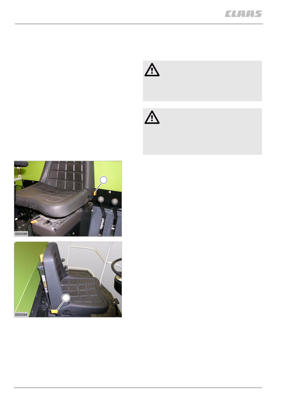
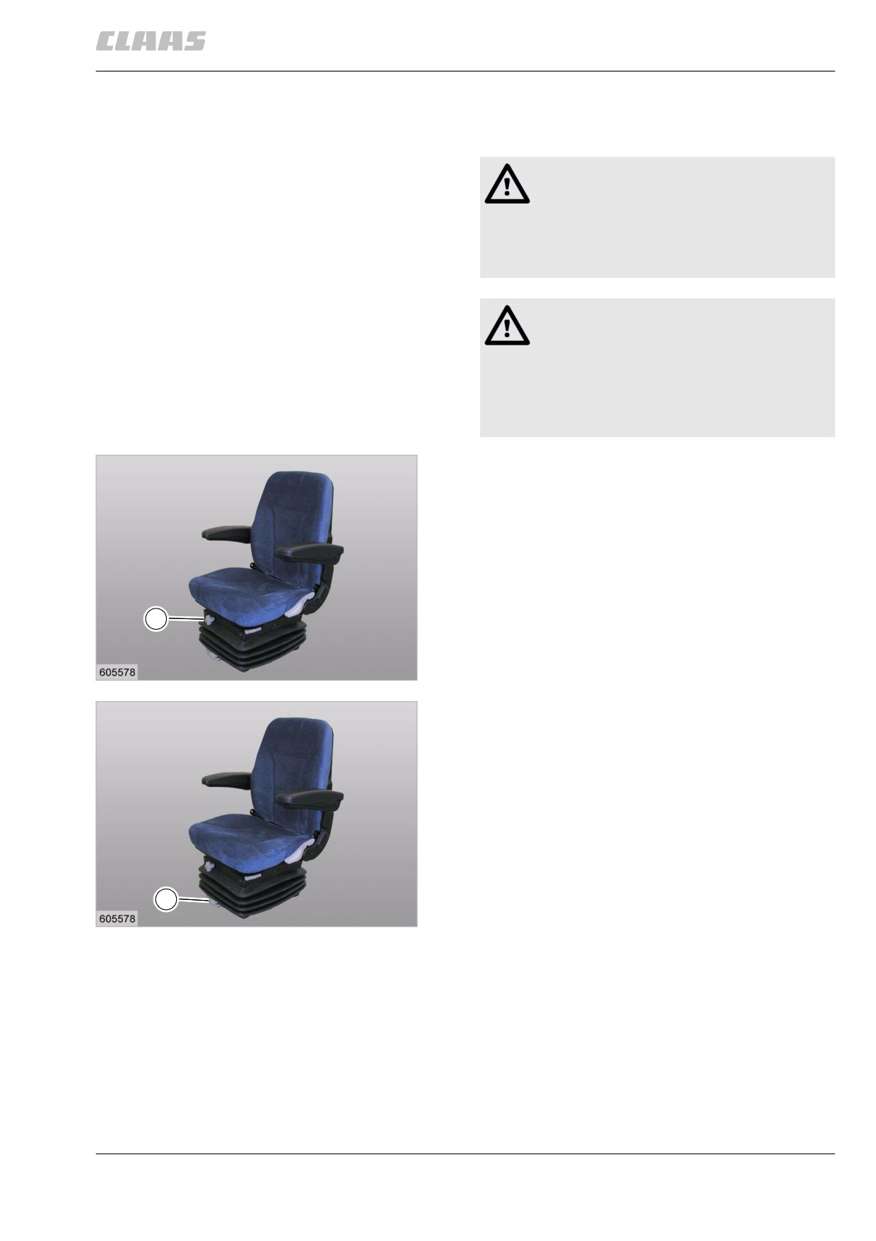
- Adjust the seat height.
- Lift lever (1) and adjust the seat up or down
until the desire seat height has been reached.
1
In the top position, the seat can be removed
upwards.
- Release lever (1).
A click is heard and lever (1) engages.
55
19421
1
56
19422
166
9 Driving and transportation
9.7 Cab / Operator's platform
67085
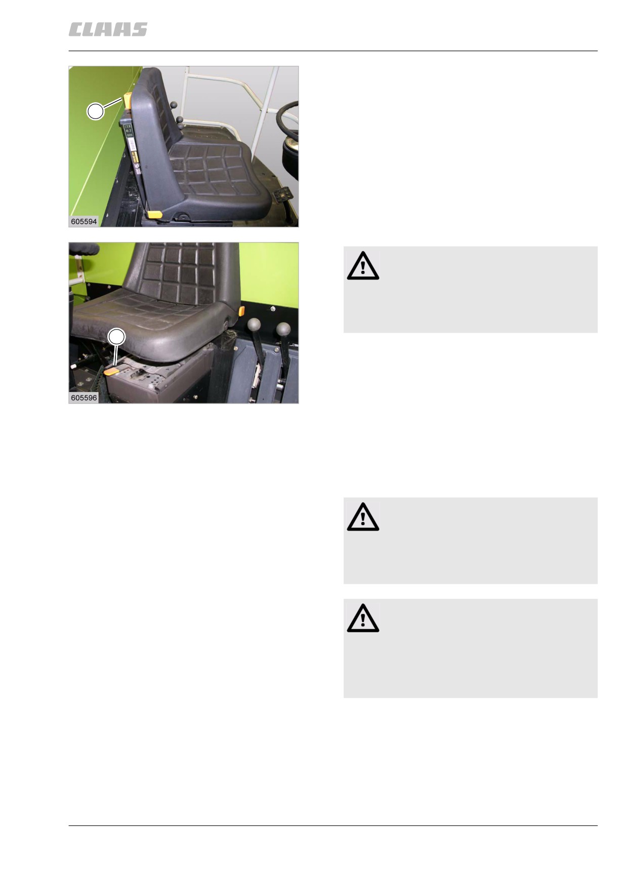
- Adjust the driver's weight.
- Turn the turn lock (1) in the desired direction
until the desired setting has been reached.
1
57
19422
Danger!
Operating error.
Death or serious injury.
- Strictly comply with instructions and
results.
1
- Adjusting the driver's sear forward and backward
- Pull up lever (1).
Slide driver's seat forward or backward.
- Release lever (1).
58
19421
A clicking sound is heard and lever (1) engages.
The driver's seat cannot be displaced any more.
81949
9.7.2 Adjusting the driver's seat with
mechanical suspension (standard version)
Danger!
Unexpected machine movements.
Death or serious injury.
- Never adjust the driver's seat while
driving!
Warning!
Driver's seat misadjusted.
Health damage.
- Before putting the machine into operation,
adapt the driver's seat ergonomically and
individually to the driver.
167
9 Driving and transportation
9.7 Cab / Operator's platform
67085
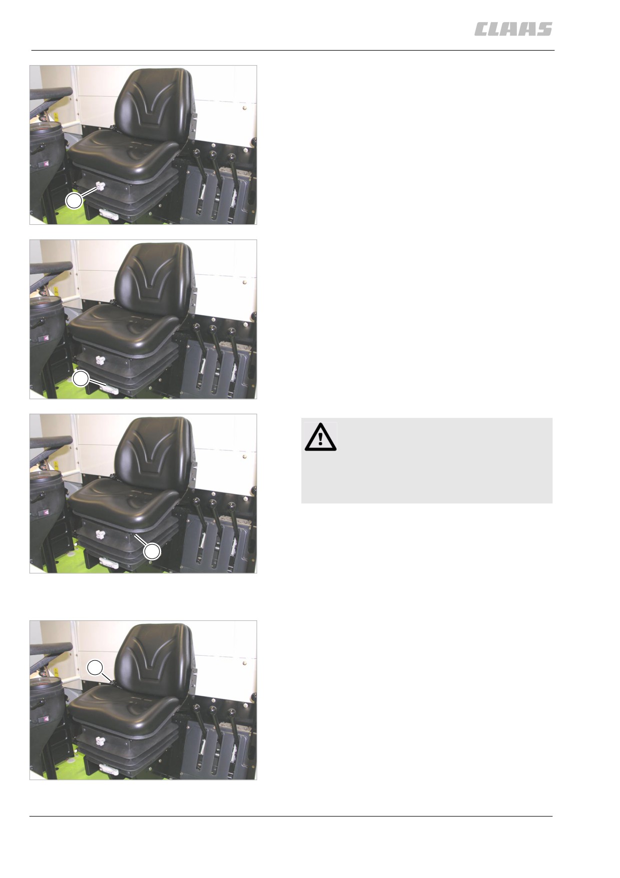
- Adjust the seat height.
- Turn the turn lock (1) in the desired direction
until the desired seat height has been reached.
1
59
28340
- Adjust the driver's weight.
- Fold out lever (1) and turn it in the desired
direction.
- Fold in lever (1).
1
60
28340
Danger!
Operating error.
Death or serious injury.
- Strictly comply with instructions and
results.
- Adjusting the driver's sear forward and backward
- Pull up lever (1).
Slide driver's seat forward or backward.
1
- Release lever (1).
61
28340
A clicking sound is heard and lever (1) engages.
The driver's seat cannot be displaced any more.
- Adjust the back rest inclination.
- Turn the turn lock (1) in the desired direction
until the desired inclination has been reached.
1
The back rest cannot be adjusted any more.
62
28340
168
9 Driving and transportation
9.7 Cab / Operator's platform
67085
80043
9.7.3 Adjusting the mechanically suspended
driver's seat (option)
Danger!
Unexpected machine movements.
Death or serious injury.
- Never adjust the driver's seat while
driving!
Warning!
Driver's seat misadjusted.
Health damage.
- Before putting the machine into operation,
adapt the driver's seat ergonomically and
individually to the driver.
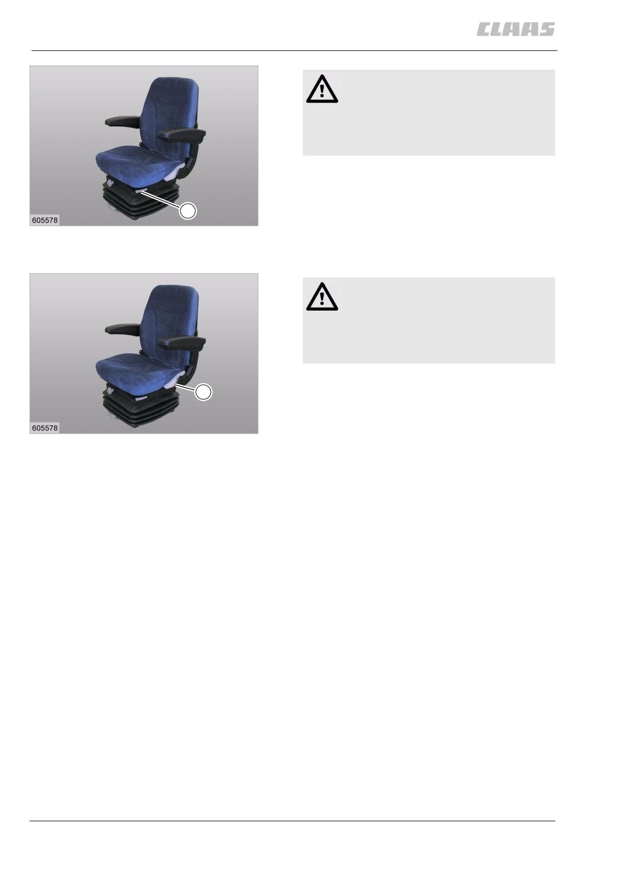
- Adjust the seat height.
- Turn the turn lock (1) in the desired direction
until the desired seat height has been reached.
3
63
19424
- Adjust the driver's weight.
- Fold out lever (1) and turn it in the desired
direction.
- Fold in lever (1).
1
64
19424
169
9 Driving and transportation
9.7 Cab / Operator's platform
67085
Danger!
Operating error.
Death or serious injury.
- Strictly comply with instructions and
results.
- Adjusting the driver's sear forward and backward
- Pull up lever (1).
Slide driver's seat forward or backward.
1
- Release lever (1).
65
19424
A clicking sound is heard and lever (1) engages.
The driver's seat cannot be displaced any more.
Danger!
Operating error.
Death or serious injury.
- Strictly comply with instructions and
results.
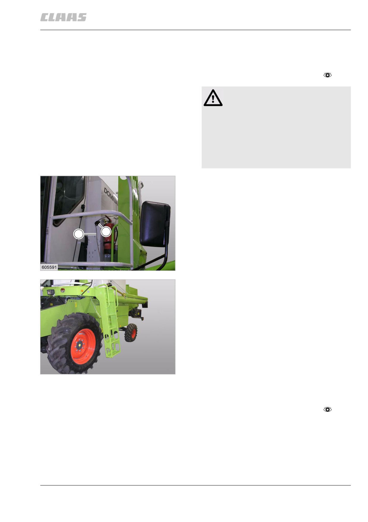
- Adjusting the back rest inclination
1
- Lift lever (1).
- Adjust back rest as desired.
- Release lever (1).
66
19424
The back rest cannot be adjusted any more.
170
9 Driving and transportation
9.8 Various components / Machine body
67085
9.8 Various components / Machine body
79697
9.8.1 Rotating the front ladder (standard)
- Observe the general warnings at the beginning of
the "Driving and transportation" chapter.
Danger!
Unexpected machine movements.
Death or serious injuries!
- Clamp the rope at the clamping piece,
thus securing the ladder against folding
down.
- Use the ladder for climbing on the
machine only when machine is standing
still.
Transport position of front ladder
- Fold up the ladder before starting road travel and
clamp it with rope (1) at the clamping piece (2),
thus securing the ladder against folding down.
2
1
67
19425
Climbing position of front ladder
- Fold ladder down before climbing up and down.
68
27339
79705
9.8.2 Adjusting the rear ladder
- Observe the general warnings at the beginning of
the "Driving and transportation" chapter.
171
9 Driving and transportation
9.8 Various components / Machine body
67085
Danger!
Unexpected machine movements.
Death or serious injuries!
- Ensure that ladder engages safely.
- Climb on ladder and machine only when
machine is standing still.
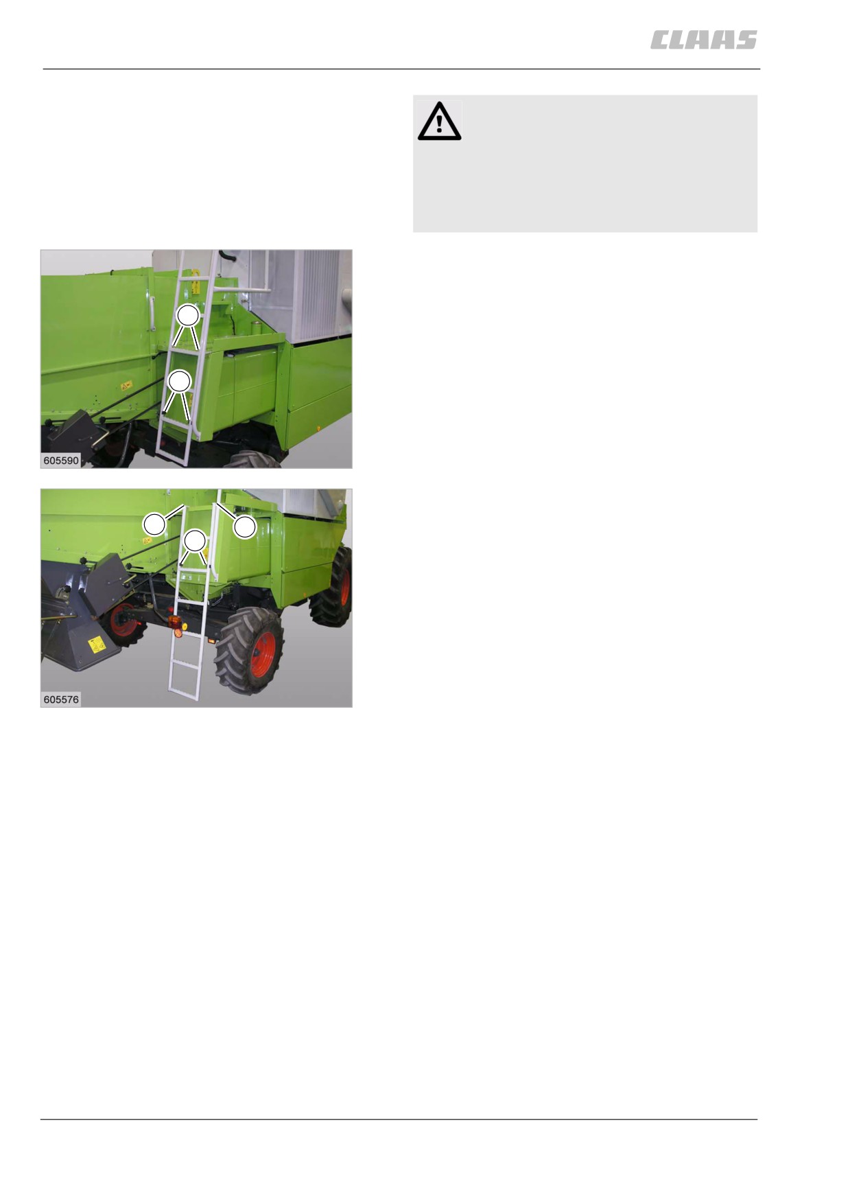
Transport position of rear ladder
- Push the ladder up every time before driving off.
- Pull ladder out of the brackets (2).
1
- Slide ladder upwards until ladder engages
safety at position (1).
- Lock ladder in brackets (2).
2
69
19427
Climbing position of rear ladder
- Pull the ladder down before climbing up.
1
1
2
- Pull ladder out of the brackets (2).
- Pull ladder downwards until ladder engages
safety at position (1).
- Lock ladder in brackets (2).
70
19426
172
10 Fieldwork settings
10.1 General Information
67086
10 Fieldwork settings
10.1 General Information
85058
10.1.1 General warnings - Fieldwork settings
In the following sections of this chapter, a procedure
instruction refers to the following general warnings.
Danger!
Always stop the engine before carrying out
any work on the machine.
Moving machine parts and / or unexpected
machine movement.
Death or serious injury.
- Diesel engine OFF.
- Apply parking brake.
- Remove the ignition key.
- Remove key of battery isolating
switch.
- Wait for machine parts which run on have
come to a complete halt.
- Secure machine by wheel chocks.
- Ensure that the machine cannot be
started by any third persons.
Danger!
The front attachment, reel and feeder unit may
drop uncontrolled.
Death or serious injuries!
- Apply safety locks.
- Keep a safe distance from the hazard
area.
173
10 Fieldwork settings
10.2 Feeder unit
67086
10.2 Feeder unit
82118
10.2.1 Adjusting the cutting height indicator
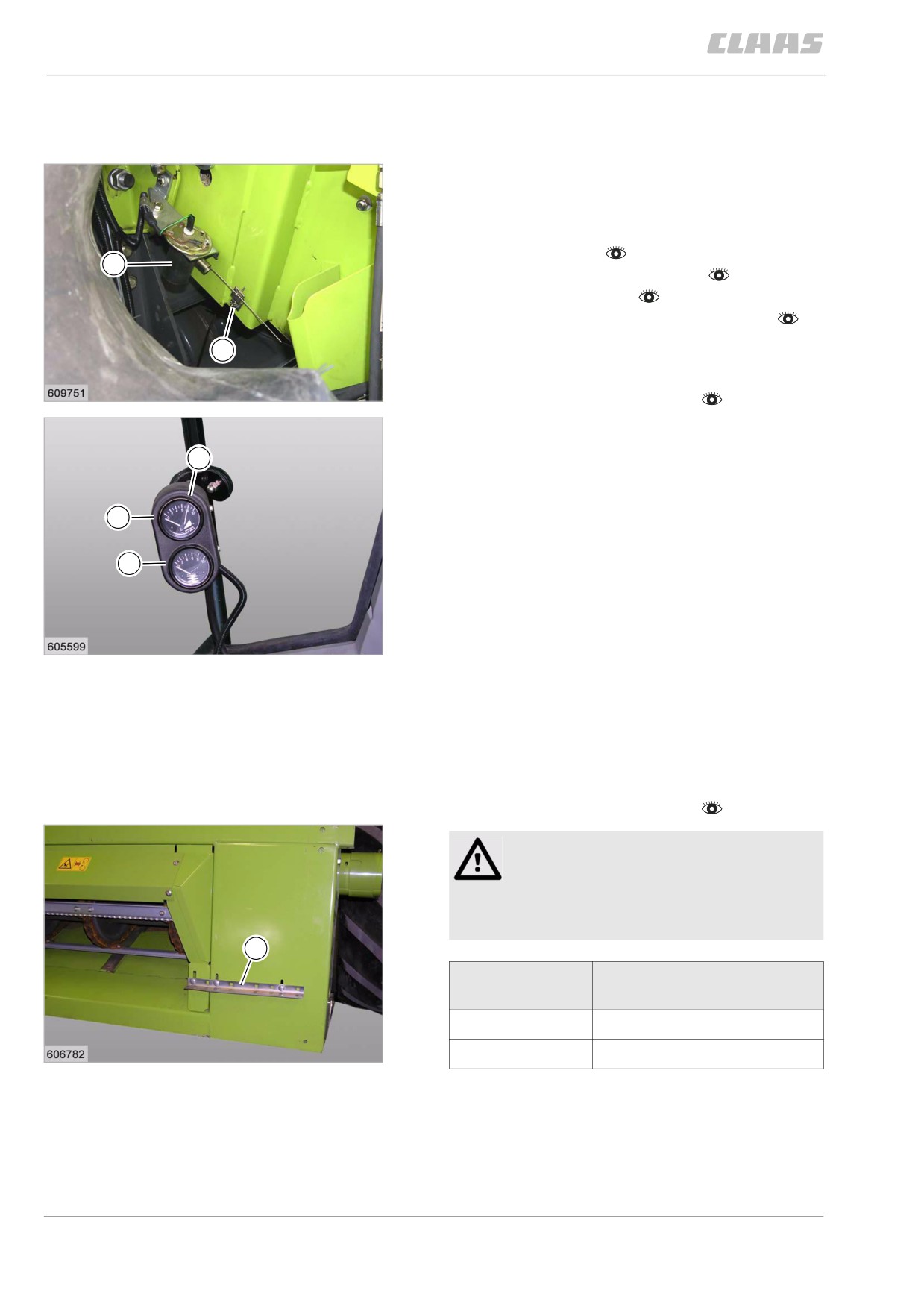
The sender (1) for the front attachment cutting height
display on the right feed rake conveyor side must be
adjusted. It shows the front attachment cutting height
above the ground.
- Prepare fieldwork.
1
- Check the cutterbar float springs.
- Start the diesel engine.
- Switch on the road travel / fieldwork switch.
- Lower front attachment until the skids are 100 mm
2
above the ground.
- Observe the general warnings at the beginning of
1
the "Fieldwork settings" chapter.
19602
- Slacken off bracket (2) and adjust it so that the
pointer on the cutting height indicator (A) stands at
9
the mark (9).
- Bolt down bracket (2).
A
B
2
19601
79341
10.2.2 Adjusting the scraper profiles
The scraper profiles influence the material flow in the
feed rake conveyor. The scraper profiles must be set
for grain or maize.
- Observe the general warnings at the beginning of
the "Fieldwork settings" chapter.
Warning!
Sharp edges and pointed machine parts.
Slight injuries.
- Wear safety gloves.
1
Crop
Scraper profile bolts down
to feed rake conveyor with
Grain
narrow leg
3
Maize
wide leg
19521
- If required, turn scraper profile (1) at the feeder
unit and bolt down hand-tight.
- Fit front attachment to the machine.
- Adjust scraper profile (1) according to the front
attachment scraper profile and bolt it down.
174
10 Fieldwork settings
10.2 Feeder unit
67086
- Repeat this process on the other side of the
machine.
72798
10.2.3 Adjusting the height of the feeder chain
- Observe the general warnings at the beginning of
the "Fieldwork settings" chapter.
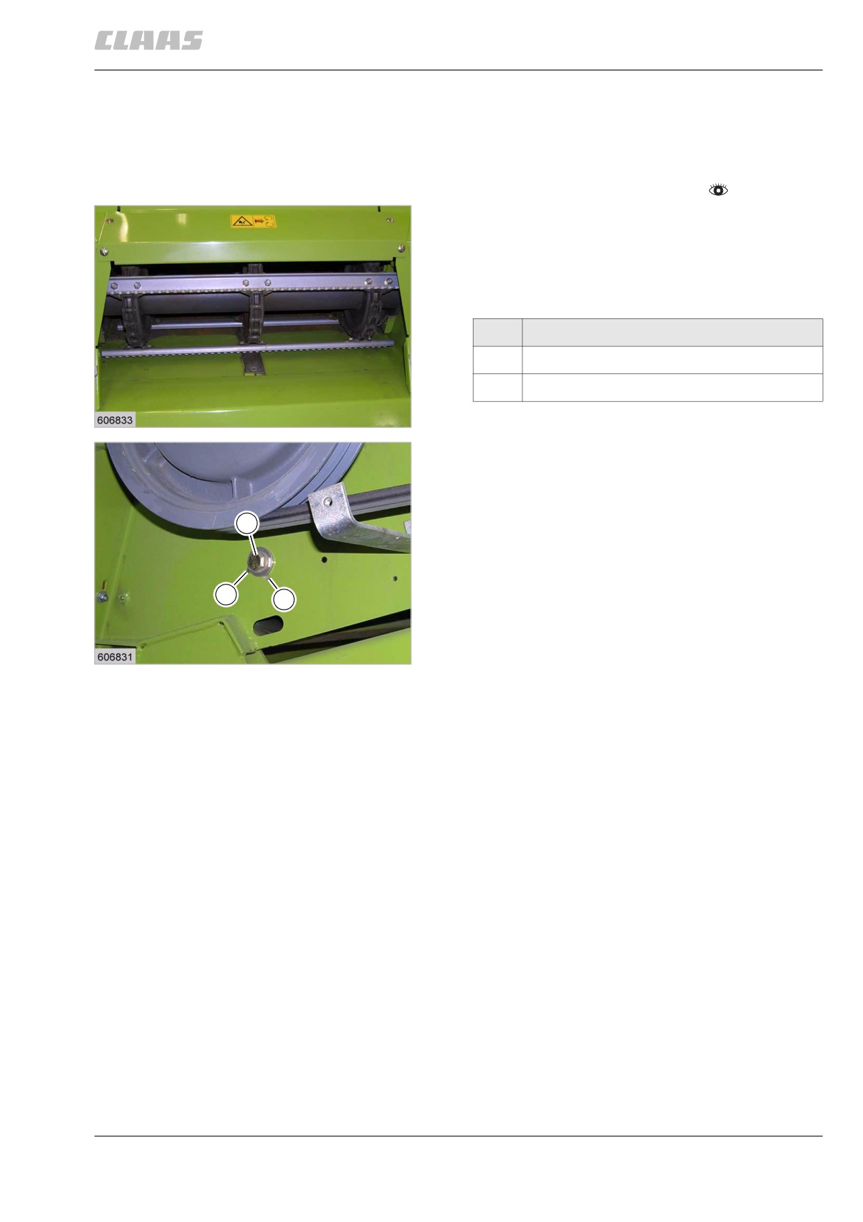
Adjust the height of the feeder chain parallel on the left
and right at the feed rake conveyor.
- Slacken off bolts (1).
- Twist supports by 90° until the dowel pin fits the
bore.
Designation
A
Grain
B
Maize
4
The supports in the feed rake conveyor have adjusted
23851
the feeder chain height.
– Bolt down bolts (1).
1
B
A
5
19596
175
10 Fieldwork settings
10.2 Feeder unit
67086
73190
10.2.4 Adjusting the front attachment drop
rate (DOMINATOR 150)
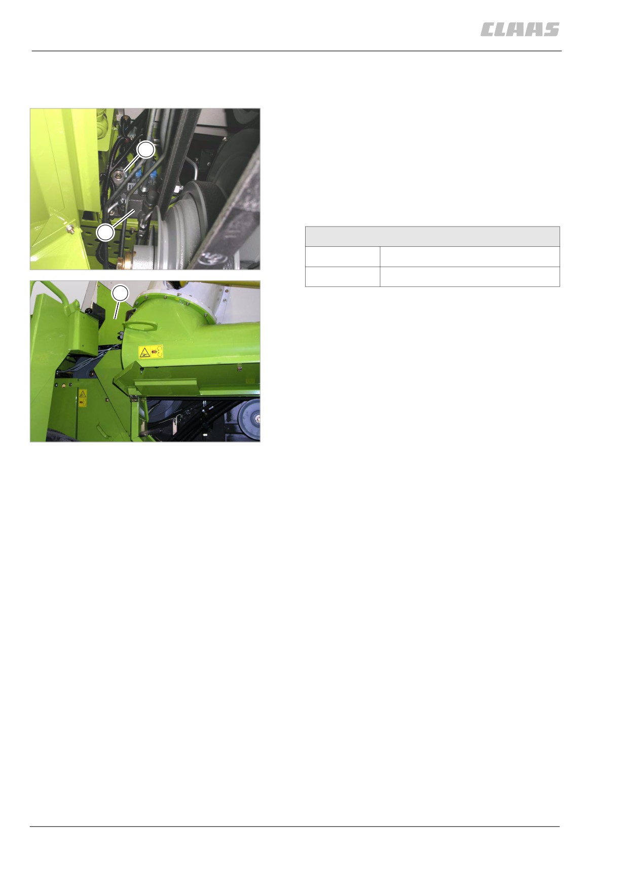
The drop rate of the front attachment can be adjusted
by turning the knurled screw (1) on the flow control
valve (2).
1
- The drop rate should be adjusted when the
hydraulic oil is at working temperature. The drop
rate is adjusted on the knurled screw (1) and
should be set so that the front attachment drops
from the top to the bottom in about 5 to 6 seconds.
2
Drop rate
Faster
turn in the knurled screw
6
25066
Slower
turn out the knurled screw
2
7
25065
176
10 Fieldwork settings
10.3 Threshing mechanism
67086
10.3 Threshing mechanism
82451
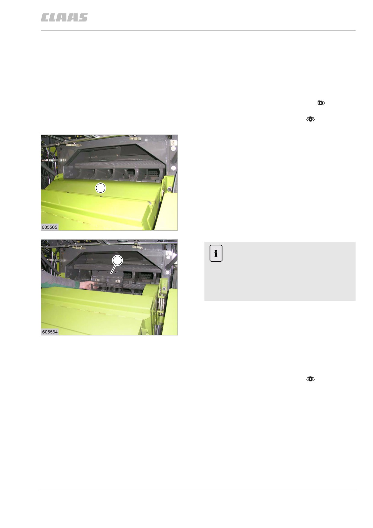
10.3.1 Removing / installing threshing con-
cave segments (Multicrop concave)
The concave segments must be installed specifically
for the crop to be harvested. See threshing chart, see
specifications
- Lower the feeder as far as possible.
- Observe the general warnings at the beginning of
the "Fieldwork settings" chapter.
- Set the threshing concave downwards.
- Open flap and unscrew cover (1).
- Unscrew bolts from the concave segments.
1
8
19619
Note!
Constructive conditions.
3
Facilitation of assembly.
- First remove the centre segment. Then
push the outer segments slightly to the
centre and remove them.
- Clean the segment guides in the concave prior to
installing the segments (3).
- Insert segments and bolt them down.
9
19621
82206
10.3.2 Adjusting the basic concave
adjustment
- Observe the general warnings at the beginning of
the "Fieldwork settings" chapter.
The clearance of the threshing concave on the right
and left sides must be parallel.
177
10 Fieldwork settings
10.3 Threshing mechanism
67086
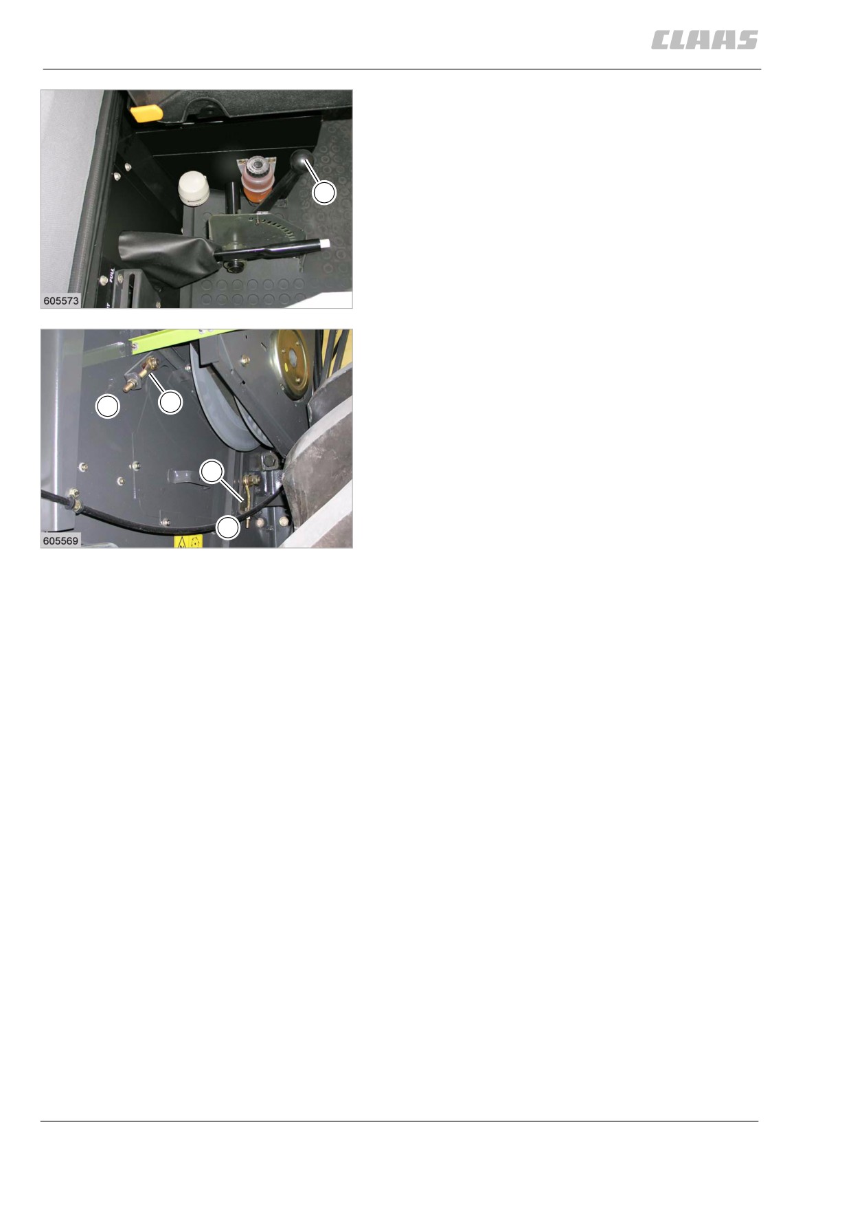
- Move the lever (H) all the way downwards. Then
let the lever (H) engage in the adjusting segment
according to the threshing concave version.
Pulling up the threshing concave ensures that it can be
correctly adjusted.
H
- Turn threshing drum by hand.
- Mark the threshing drum beater bar with the larg-
est radius (measuring bar) on the left and right
machine side.
The clearance from the threshing concave is then
adjusted at this marked beater bar.
10
19428
- Set the distances (A and B) of the threshing con-
cave on both sides at the turnbuckles (1) of the
tow bars.
- Loosen the nuts of the turnbuckles (1).
1
B
- Adjust the turnbuckles until you obtain the
threshing concave basic adjustment.
- Check the distances (A and B) again.
- Lock the nuts of the turnbuckles (1).
1
A
11
19607
178
10 Fieldwork settings
10.3 Threshing mechanism
67086
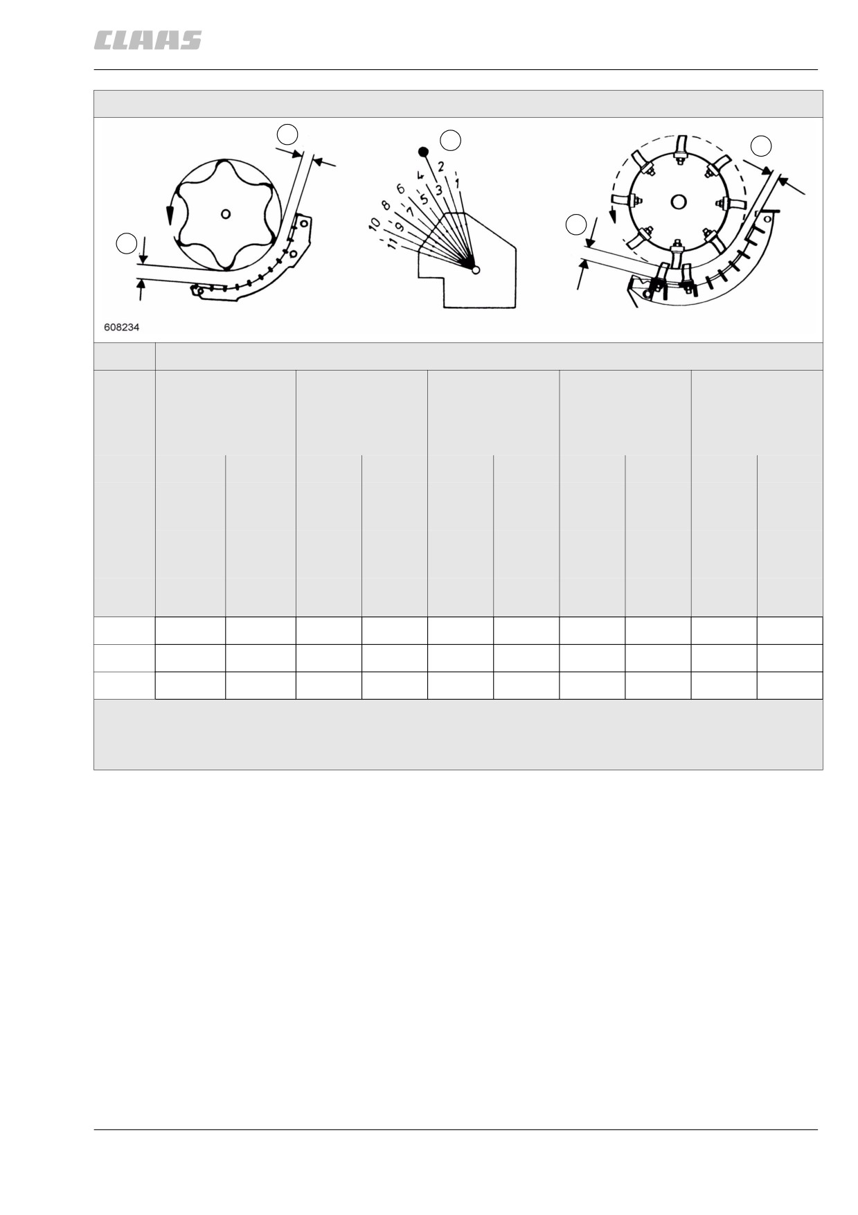
Basic concave adjustment
B
H
B
A
A
Main concave
Wire N10 **
Wire N10 ***
Wire N18 **
Sheet-metal (19
Spike tooth**
x 40)***
Wire N12 **
Sheet-metal
(10 x 38)***
A
B
A
B
A
B
A
B
A
B
Meas-
3rd
10th
2nd
9th
3rd
2nd last
2nd
9th
1st
3rd last
uring
**
**
bar
2nd
9th
***
***
Lever H
(mm)
(mm)
(mm)
(mm)
(mm)
(mm)
(mm)
(mm)
(mm)
(mm)
(hole)
2
15 *
8 *
3
13 *
3 *
13 *
5 *
8
40 *
20 *
33 *
17 *
** = Basic concave adjustment, ** = Continuous concave, *** = Multicrop concave with 3 concave
segments
A = Concave entrance, B = Concave exit
179