CLAAS DOMINATOR 150 / 140 / 130. Operator’s Manual - page 10
9 Driving and transportation
9.2 Engine
67085
Danger!
When starting the machine, persons are on
the machine or in its hazard area.
Death or serious injury.
- Before starting the machine ensure that
there are no persons or objects in the
hazardous area.
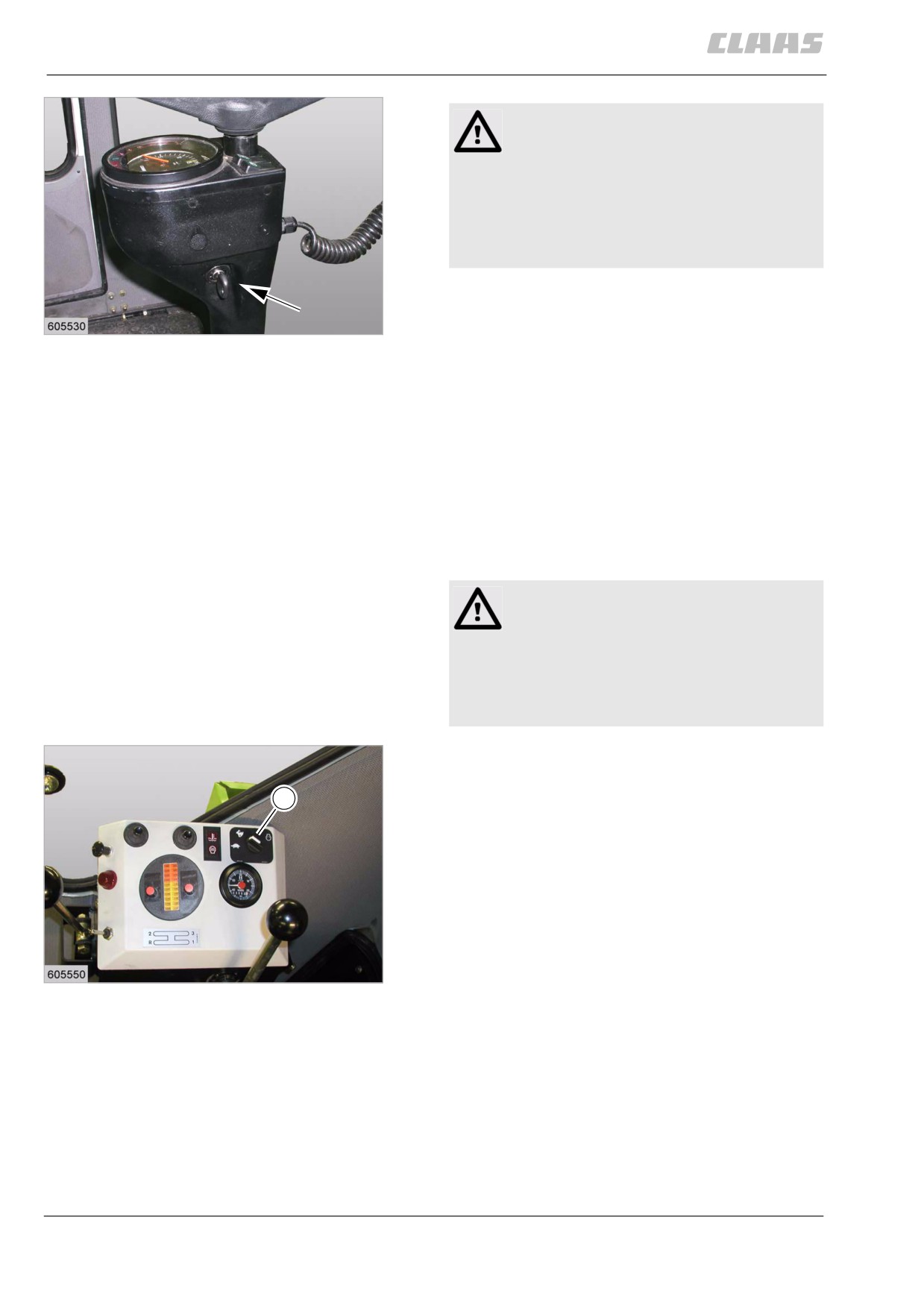
- Turn the ignition key to position 1.
- Turn the ignition key to the limit stop until the die-
22
sel engine starts.
19363
Do not hold the ignition key at the limit stop
for more than 10 seconds!
- Release the ignition key.
The ignition key engages and the diesel engine is
started.
At low outside temperatures, let diesel engine run at
min. no-load speed for some minutes after starting.
80095
9.2.6 Stopping the diesel engine
(DOMINATOR 130)
Warning!
Overheating of the turbocharger.
Machine damage.
- Before turning off, first let the diesel
engine run a short time at slow idling
speed.
CATERPILLAR C-6.6, 3056E
- Set the diesel engine speed rotary control
1
switch (1) to the min. no-load speed.
23
CATERPILLAR C6.6, 3056E
19412
148
9 Driving and transportation
9.2 Engine
67085
Perkins 1006-T6
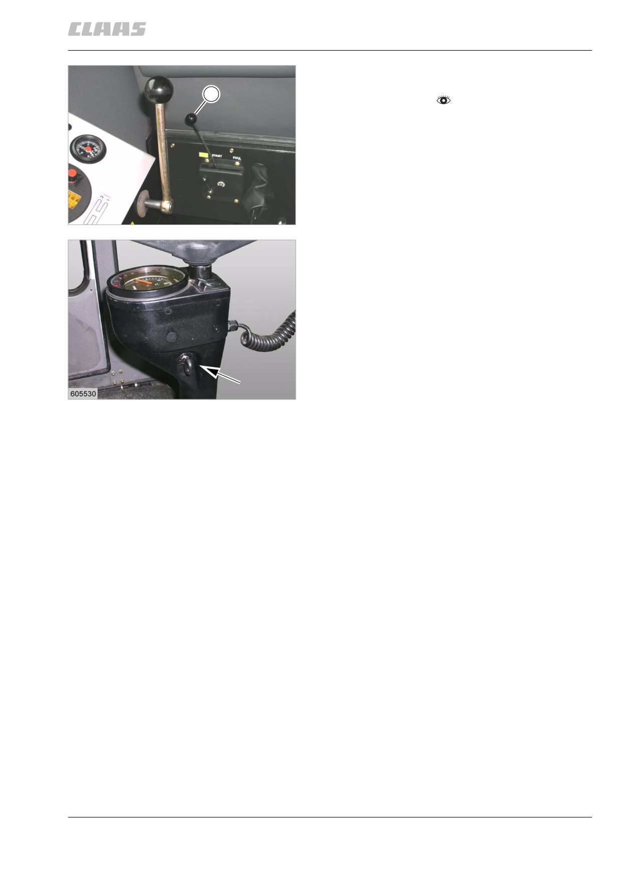
- Set the diesel engine speed lever (1) to the
1
START position.
24
Perkins 1006-T6
29771
- Disengage all drives previously engaged.
- Turn the ignition key to position 0.
The diesel engine stops.
25
19363
149
9 Driving and transportation
9.3 Chassis
67085
9.3 Chassis
80177
9.3.1 Ground speed control lever
(DOMINATOR 150 / 140)
The bottom part of the multi-function handle is referred
to as the ground speed control lever.
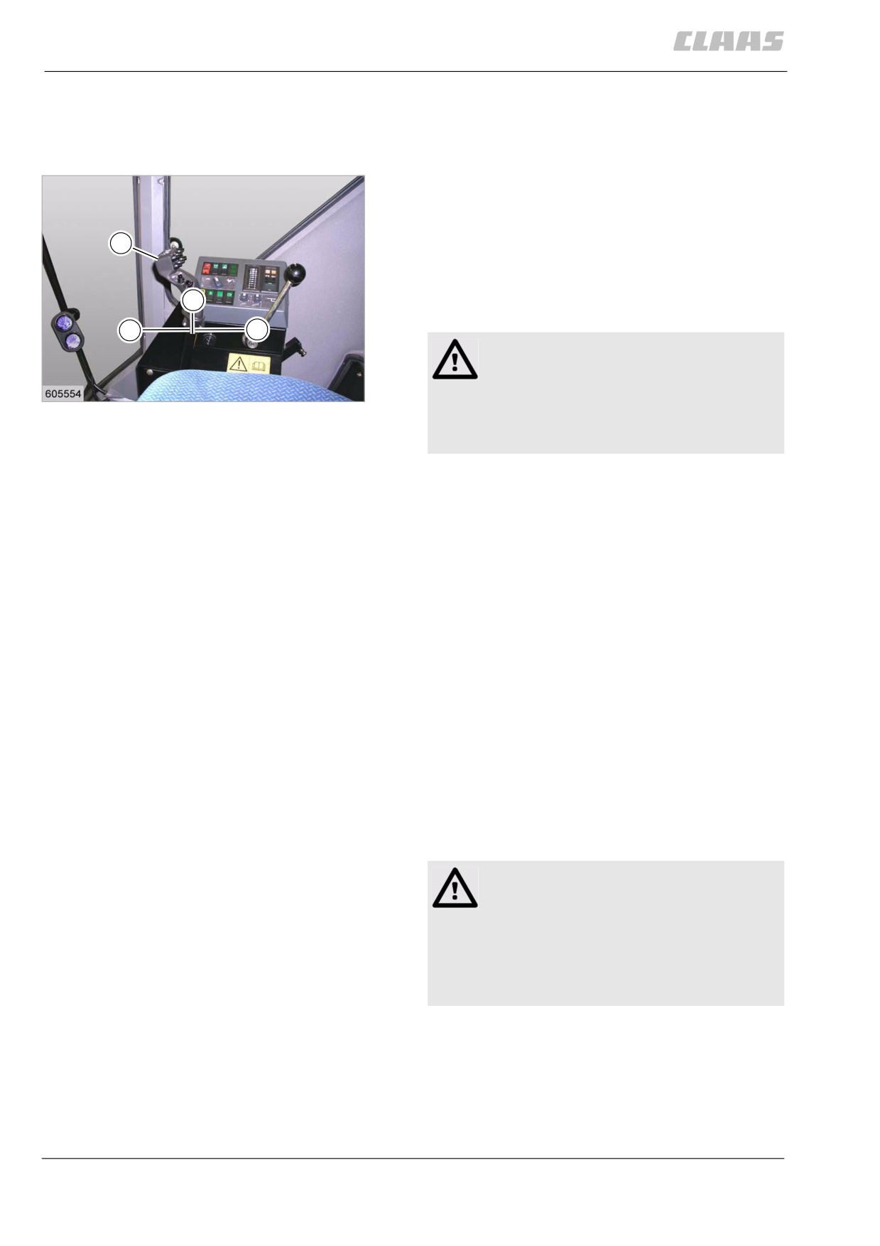
The ground speed control lever (1) sets the direction of
1
travel and the ground speed within the respective
gears in an infinitely variable way.
The respective gears must be engaged separately
N
before starting off. See Shifting gears.
A
B
WARNING:
Sensitive components.
26
Material damage
19459
- Actuate the ground speed control lever
only with the engine running.
Forward travel
The further the ground speed control lever (1) is
moved from the neutral position (N) in direction (A),
the higher the forward travel speed will be.
Stopping
The further the ground speed control lever (1) is
moved to the neutral position (N), the slower the
machine moves.
When the ground speed control lever (1) is in neutral
position (N), the machine stops. In addition, depress
the foot brake pedals downwards. See braking / stop-
ping the machine.
Reverse travel
The further the ground speed control lever (1) is
moved from the neutral position (N) in direction (B),
the higher the reverse travel speed will be.
80211
9.3.2 Shifting a gear (DOMINATOR 150 / 140)
Danger!
Machine starts to move unexpectedly.
Death or serious injury.
- Never shift gears while driving!
- Never shift gears while driving on slopes.
- Do not let the machine roll.
- Stop the machine.
- Move the ground speed control lever to neutral.
- In addition, depress the foot brake pedals
downwards.
150
9 Driving and transportation
9.3 Chassis
67085
-
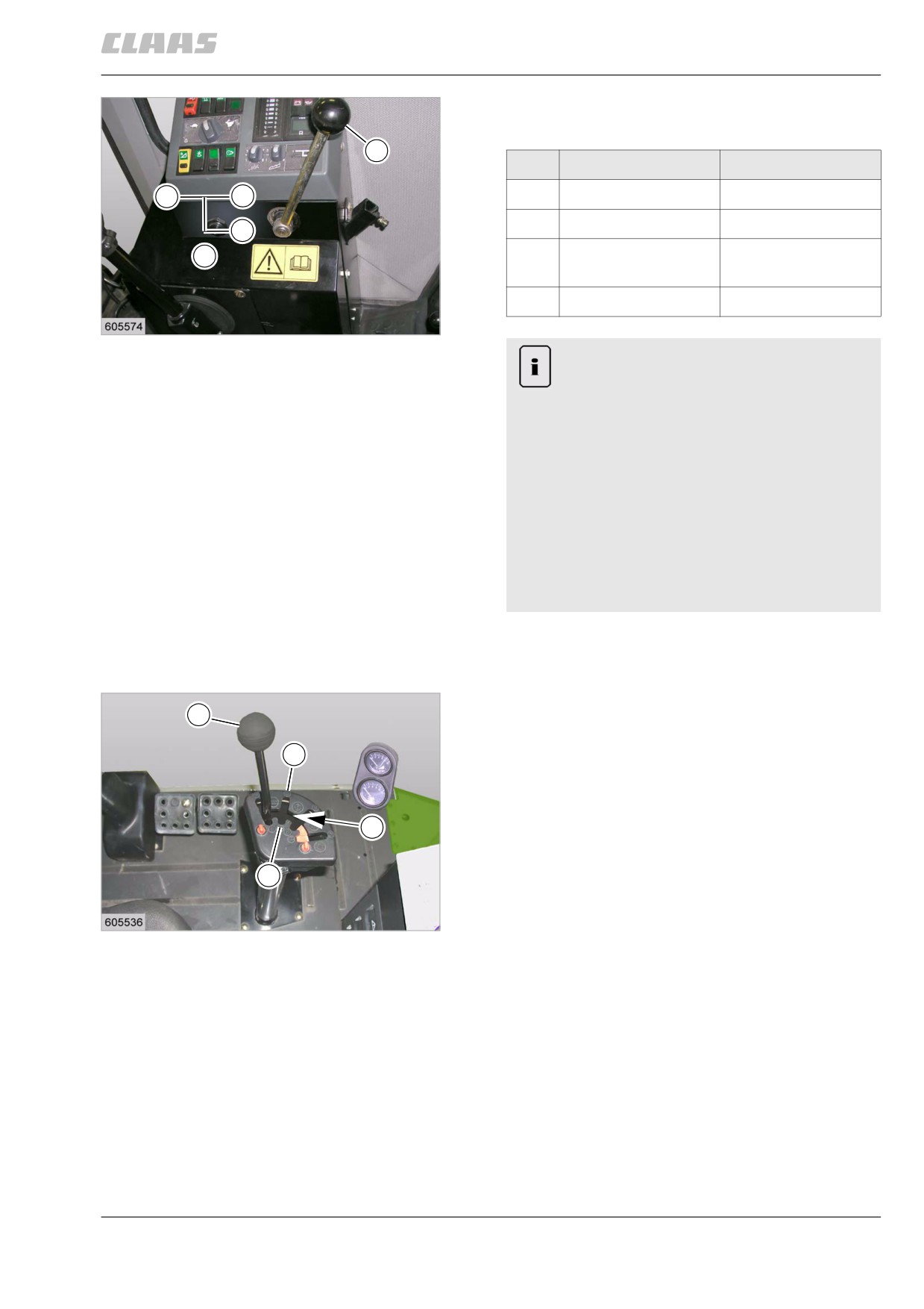
Using the shift lever (4), adjust the machine to the
desired switch position.
4
Gear
Designation
2
3
N
Neutral position
1
1st gear
Fieldwork gear
1
N
2
2nd gear
Fieldwork gear /
road gear
3
3rd gear
Road gear
27
19430
Note!
Shift lever locks during shifting.
Gear is difficult to engage.
- Set shift lever in neutral.
- Release foot brake pedals.
- Briefly actuate the ground speed control
lever with the engine running.
- Set ground speed control lever to neutral
while the engine is running.
- Depress the foot brake pedals
downwards.
- Set shift lever to desired shift position.
80238
9.3.3 Ground speed control lever
(DOMINATOR 130)
The control lever of the control unit for the ground
1
speed function in gate (3 / 4) is referred to as the
ground speed control lever (1).
3
The ground speed control lever sets the speed within
the respective gears in an infinitely variable way. After
actuating the control unit, the control lever automati-
cally returns to neutral (N) from any position.
N
The respective gears must be engaged separately
before starting off. See Shifting gears.
4
Reducing the ground speed
28
- Move the ground speed control lever (1) from the
19409
neutral position (N) towards (3), thus reducing the
ground speed within the selected gear.
151
9 Driving and transportation
9.3 Chassis
67085
Danger!
The ground speed is only reduced, the
machine will not stop with this function.
Death or serious injuries!
- Make yourself familiar with this function.
- Brake / stop the machine.
- Depress the clutch pedal fully.
- Depress the foot brake pedals
downwards.
Increasing the ground speed
- Move the ground speed control lever (1) from the
neutral position (N) towards (4), thus increasing
the ground speed within the selected gear.
80236
9.3.4 Shifting a gear (DOMINATOR 130)
Danger!
Machine starts to move unexpectedly.
Death or serious injury.
- Never shift gears while driving!
- Never shift gears while driving on slopes.
- Do not let the machine roll.
- Stop the machine.
- In addition, depress the foot brake pedals
downwards.
152
9 Driving and transportation
9.3 Chassis
67085
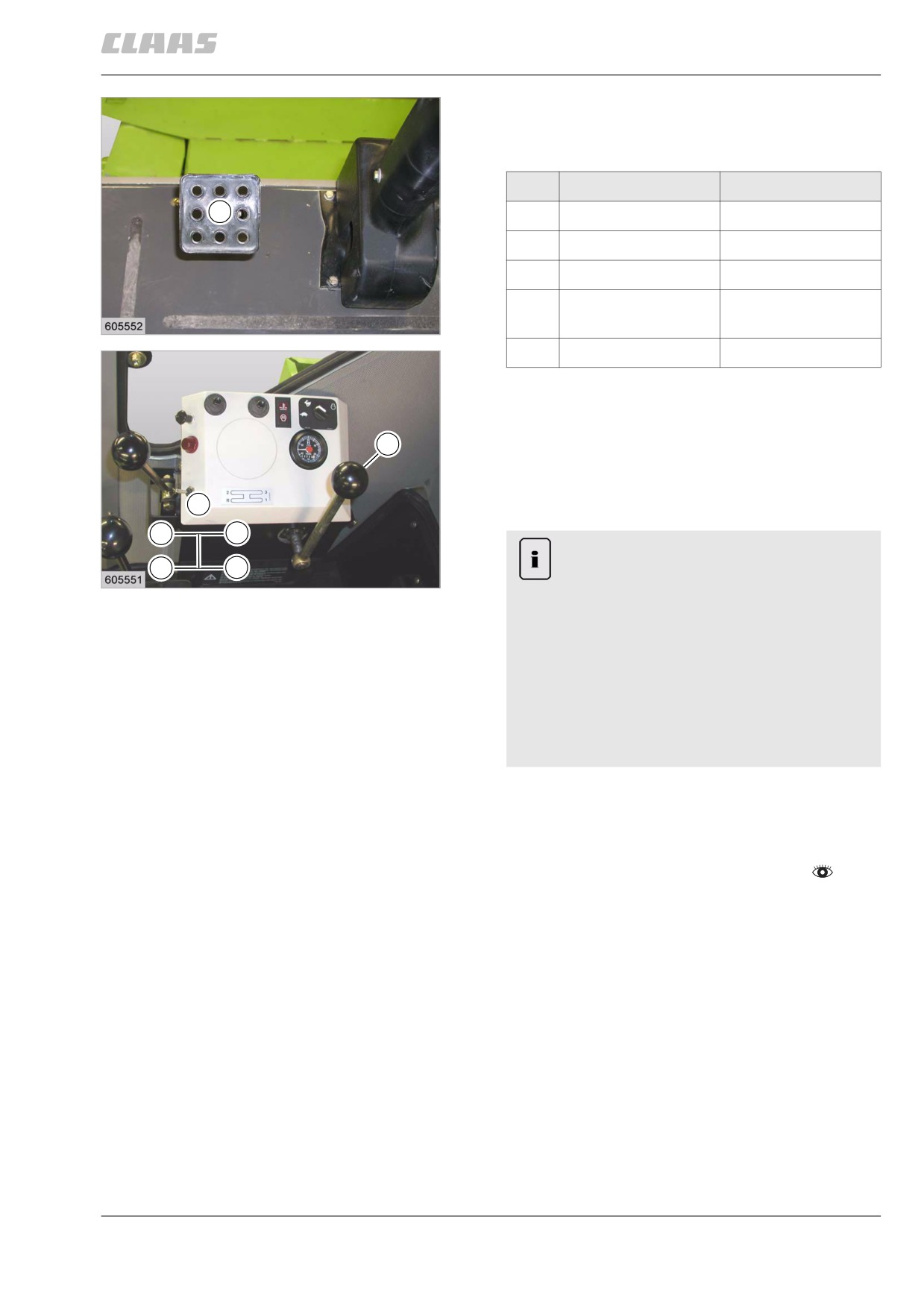
- Depress the clutch pedal (5) fully.
- Using the shift lever (4), adjust the machine to the
desired switch position.
Gear
Designation
5
N
Neutral position
R
Reverse gear
1
1st gear
Fieldwork gear
2
2nd gear
Fieldwork gear /
29
road gear
19458
3
3rd gear
Road gear
- Release parking brake if required.
- After the gear has been engaged, release pedals
of foot brake and slowly release the clutch pedal.
4
Take the foot off of the clutch pedal (5), thus
avoiding unnecessary clutch drag.
The clutch engages and the machine starts off.
N
2
3
Note!
R
1
Shift lever locks during shifting.
30
19457
Gear is difficult to engage.
- Release parking brake if required.
- Release foot brake pedals.
- Slowly release the clutch pedal.
- Depress the clutch pedal fully.
- Depress the foot brake pedals
downwards.
- Set shift lever to desired shift position.
80261
9.3.5 Adjusting the ground speed control lever
actuating resistance (DOMINATOR 150 / 140)
- Observe the general warnings at the beginning of
the "Driving and transportation" chapter.
153
9 Driving and transportation
9.3 Chassis
67085
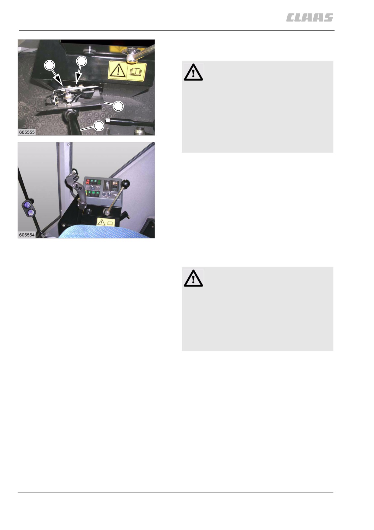
The operating smoothness of the ground speed control
lever (1) can be adapted to the operator.
3
3
Danger!
Unexpected machine movements.
Death or serious injury.
- Never adjust the operating smoothness of
2
the ground speed control lever while
driving.
- Do not set the operating smoothness too
1
31
low.
19460
- Adjust the operating smoothness accord-
ing to the instructions.
- Unscrew plate (2).
- Adjust the actuating resistance at the set
screws (3).
Adjust actuating resistance so that the ground
speed control lever cannot move independently
while the machine is driving.
A hand force on the handle of 25 - 30 N should
be required as a guideline value for moving
the ground speed control lever.
32
- Mount plate (2).
19459
4277
9.3.6 Driving behaviour
Danger!
Unexpected machine movements.
Death or serious injury.
- Adapt your driving style to the local terrain
and ground conditions.
- Adapt your driving style to the load
carried.
- Be especially careful when working on
slopes!
40736
9.3.7 Towing the machine
The machine should be towed only if this is absolutely
necessary.
154
9 Driving and transportation
9.3 Chassis
67085
Danger!
Towing the machine.
Death or serious injury.
Serious machine damage.
- Tow machine only when absolutely
necessary.
- Do not tow machine over an extended
distance.
- Consider that steering is heavier when
the engine is shut down.
- Use suitable towing tools.
- Tow machine only with no gear engaged.
80174
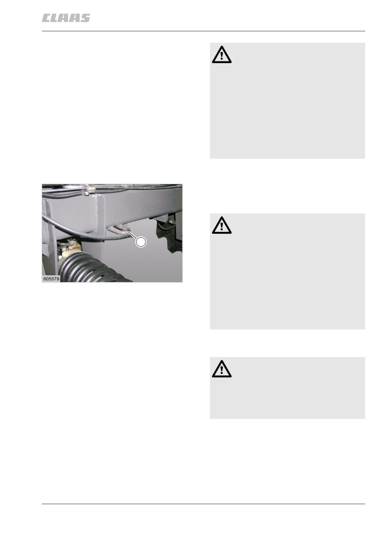
9.3.8 Forward towing
A tow rope or chain can be attached to the traction
eye (1) of the drive axle for towing the combine
forward.
Danger!
Towing the machine.
1
Death or serious injury.
Serious machine damage.
- Tow machine only when absolutely
necessary.
33
- Do not tow machine over an extended
19472
distance.
- Consider that steering is heavier when
the engine is shut down.
- Use suitable towing tools.
- Tow machine only with no gear engaged.
40755
9.3.9 Reverse towing
Caution
Towing backwards.
Machine damage.
- Do not tow machine backwards.
- Do not attach any tow rope / tow chain to
the drawbar hitch / axle body.
155
9 Driving and transportation
9.4 Brake
67085
9.4 Brake
80311
9.4.1 Applying the parking brake
The parking brake functions independently of the foot
brake.
When the ignition is ON and the parking brake applied,
the symbol
is displayed in the on-board informa-
tion system.
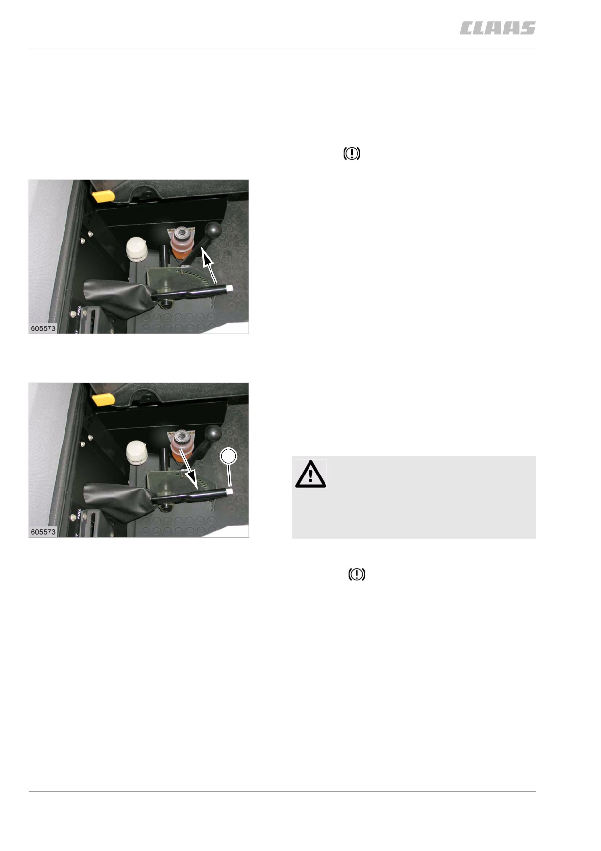
- Pull the parking brake lever up with your hand and
let lever engage.
- Make sure that the parking brake is sufficiently
applied.
The parking brake is applied.
34
19428
80315
9.4.2 Releasing the parking brake
- Slightly pull up the parking brake lever with your
hand and push pin (1) until the pawl has
disengaged.
- Keep pin pressed and lower the parking brake
lever fully.
1
WARNING:
Applied brakes become hot during driving.
Machine damage
- Always release the parking brake all the
35
way before driving.
19428
The parking brake is released.
The symbol
in the onboard information system
disappears.
80316
9.4.3 Foot brake
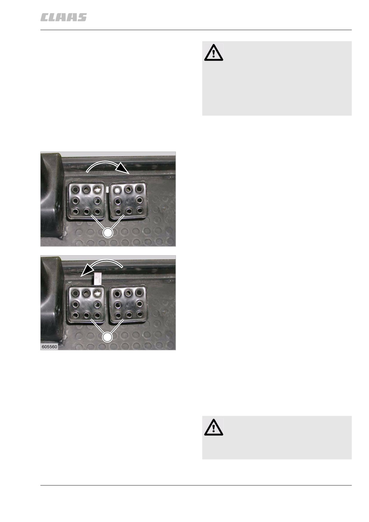
The foot brake can be used both as a conventional
brake and as an independent brake.
156
9 Driving and transportation
9.4 Brake
67085
Danger!
Use of independent brake on public roads and
lanes.
Death or serious injury.
- Lock the foot brake pedals together
before travel on public roads and lanes.
- Use the independent brakes exclusively
during work in the field.
The independent brake serves for handling tight bends
or as a steering aid on muddy ground.
The brake settings are as follows:
• Conventional brake with coupled brake pedal (1).
1
36
27491
• Independent brake with uncoupled brake
pedal (1).
1
37
19469
80321
9.4.4 Braking / stopping the machine
(DOMINATOR 150 / 140)
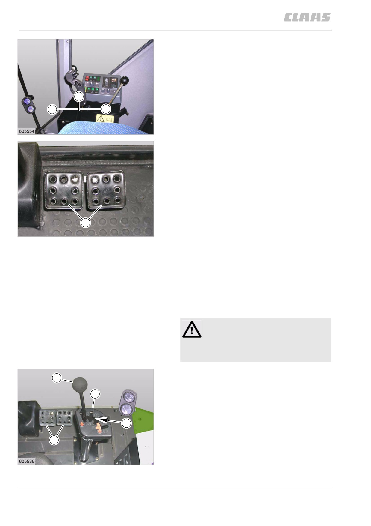
While driving, the machine can be decelerated and
stopped using the multifunction lever.
The machine can also be braked using the foot brake.
Danger!
Use of the independent brake.
Death or serious injuries!
- Couple the foot brake pedals.
157
9 Driving and transportation
9.4 Brake
67085
Brakes:
- Move the ground speed control lever towards the
neutral position (N).
- In addition, depress the foot brake pedals (1)
downwards.
Stopping:
N
- Move the ground speed control lever towards the
neutral position (N).
A
B
- In addition, depress the foot brake pedals (1)
downwards.
38
19459
1
39
27491
81797
9.4.5 Braking / stopping the machine
(DOMINATOR 130)
While driving, the machine ground speed can be
reduced within the selected gear using the ground
speed control lever and the foot brake.
While driving, the machine can be decelerated and
stopped by depressing the clutch and the foot brake.
Danger!
Use of the independent brake.
Death or serious injuries!
- Couple the foot brake pedals.
Brakes:
1
- Move the ground speed control lever (1) from the
neutral position (N) towards (3), thus reducing the
3
ground speed within the selected gear.
N
4
40
19409
158
9 Driving and transportation
9.4 Brake
67085
Danger!
The ground speed is only reduced, the
machine will not stop with this function.
Death or serious injuries!
- Make yourself familiar with this function.
- Brake / stop the machine.
- Depress the clutch pedal fully.
- Depress the foot brake pedals
downwards.
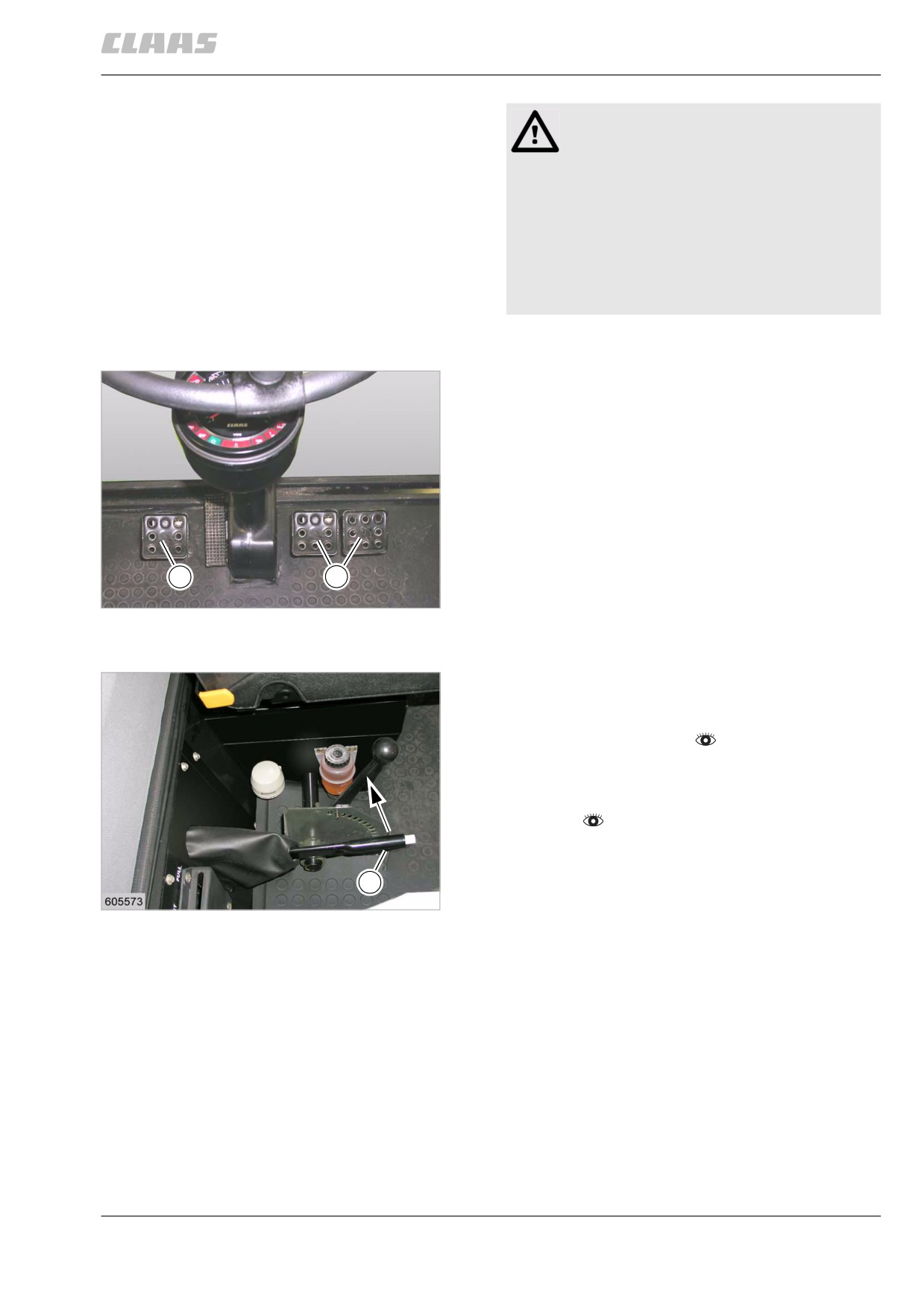
- In addition, depress the foot brake pedals (4)
downwards.
Stopping:
- Depress the clutch pedal (5) fully.
- Depress the foot brake pedals (4) downwards.
- When the machine is standing still, disengage the
gear.
5
4
41
28292
81794
9.4.6 Parking the machine
- Drive the machine on solid ground.
- Engage the parking brake using the parking brake
lever (1).
- Stop the diesel engine.
- Remove the ignition key.
- When parking the machine on a slope, secure the
machine against rolling away with a wheel
chock.
1
42
19428
159
9 Driving and transportation
9.5 Steering
67085
9.5 Steering
4284
9.5.1 Steering
The hydrostatic steering enables easy steering of the
machine with the rear wheels.
Danger!
The machine swings out at the rear.
Death or serious injury.
- Be careful when driving on public roads.
- Be careful when taking tight bends.
The steering continues to function even with the
engine stopped. But a much greater steering effort is
required.
81838
9.5.2 Adjusting the steering column
Danger!
Unexpected machine movements.
Death or serious injury.
- Never adjust the steering column while
driving!
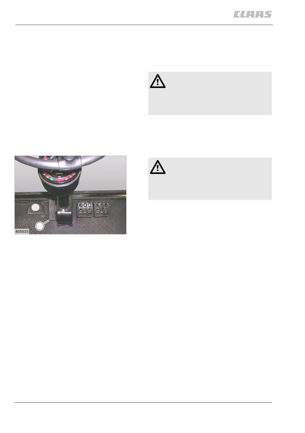
Adjusting the steering column
- Seize the steering wheel with the hand.
- Press lever (1) with the foot at the front and loosen
1
the steering column.
43
19369
Move the steering column to the desired position
by hand.
- Press lever (1) with the foot at the rear, thus
arresting the steering column.
The steering column is now arrested in the desired
position.
160
9 Driving and transportation
9.6 Hitch
67085
9.6 Hitch
81910
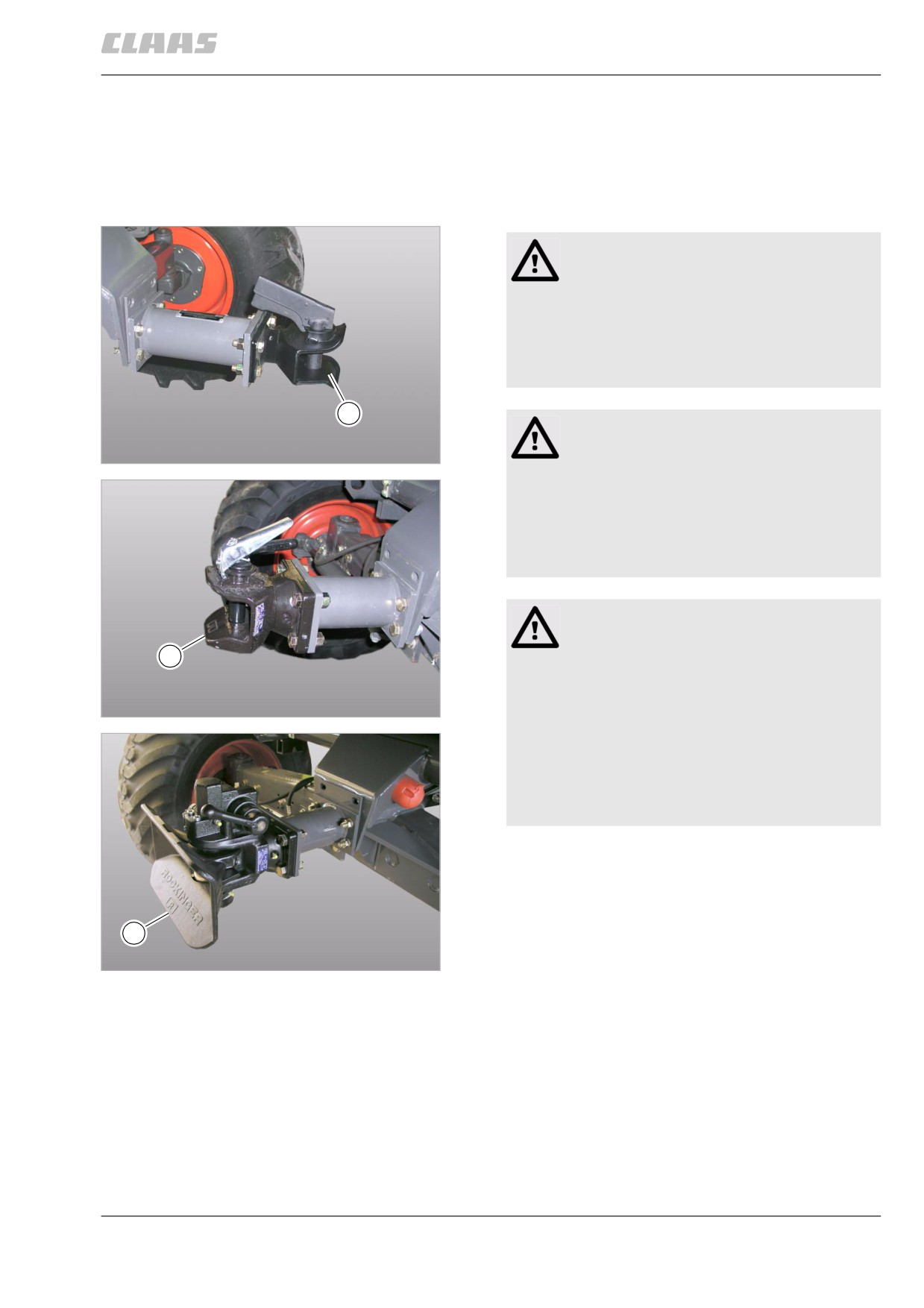
9.6.1 Hitching the trailer
-
Identify the trailer hitch by means of the identifica-
tion plate on the trailer hitch.
Observe the type-specific details.
Warning!
Travel in uneven terrain.
Tail of machine will drop.
Machine damage.
- Ensure clearance between machine and
trailer.
2
Danger!
Exceeding permissible loads.
44
Trailer hitch type AK 64/1 B ...
24699
Death or serious injuries!
- Do not exceed permissible axle load and
drawbar load of the trailer.
- Do not exceed permissible axle load and
drawbar load of the tractor.
Danger
Limbs within range of the trailer hitch or the
2
trailer.
Risk of death or serious injuries.
45
- Keep limbs away from the trailer hitch.
Trailer hitch type 810 ...
40022
- Never remain standing between the trailer
hitch and the trailer.
- Observe the regulations of the German
employers' liability insurance association
or its equivalent.
2
46
Trailer hitch type 841 ...
36440
161
9 Driving and transportation
9.6 Hitch
67085
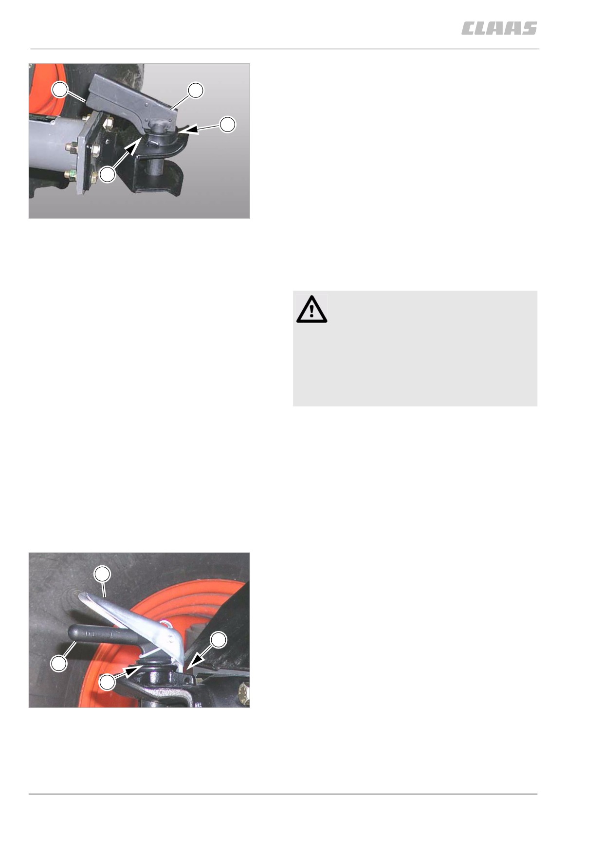
Type AK 64/1 B ...
-
Secure the rear axle of the transport carriage so it
4
5
will not roll away.
-
If required, release the trailer steering axle brake.
6
The drawbar must be freely moving in all
directions.
With rigid-drawbar trailers, the hitch eye must hit
the centre of the hitch (2).
7
Failure to observe this rule will cause damage!
-
If required, set the hitch eyes to the height of the
coupling point.
47
-
Press pawl (4) and handle of pin (5) together and
Trailer hitch type AK 64/1 B ...
30204
pull out of the trailer hitch.
-
Clean the trailer hitch with a suitable agent.
–
Back up tractor slowly until the hitch eye makes
contact with the trailer hitch.
Danger!
Lock not engaged.
Trailer releases from the towing vehicle.
Death or serious injuries!
- Ensure that the lock is securely engaged.
- Never pull a trailer with the lock
disengaged.
-
Press pawl (4) and handle of pin (5) together and
plug pin (5) into the trailer hitch up to the stop (6).
-
Release the pawl (4) and ensure that lock (7) has
engaged at the trailer hitch.
-
Raise the trailer support wheel.
–
Connect the power supply plug.
–
If present, connect the breakaway cord to the
trailer hitch.
-
Check the trailer lighting.
–
If there is a braking system, carry out a brake test.
Type 810 ...
4
- Secure the rear axle of the transport carriage so it
will not roll away.
- If required, release the trailer steering axle brake.
The drawbar must be freely moving in all
directions.
7
With rigid-drawbar trailers, the hitch eye must hit
the centre of the hitch (2).
5
Failure to observe this rule will cause damage!
6
- If required, set the hitch eyes to the height of the
coupling point.
48
- Push down pawl (4) and pull pin (5) out of the
Trailer hitch type 810 ...
20717
trailer hitch.
- Clean the trailer hitch with a suitable agent.
- Back up tractor slowly until the hitch eye makes
contact with the trailer hitch.
162
9 Driving and transportation
9.6 Hitch
67085
Danger!
Lock not engaged.
Trailer releases from the towing vehicle.
Death or serious injuries!
- Ensure that the lock is securely engaged.
- Never pull a trailer with the lock
disengaged.
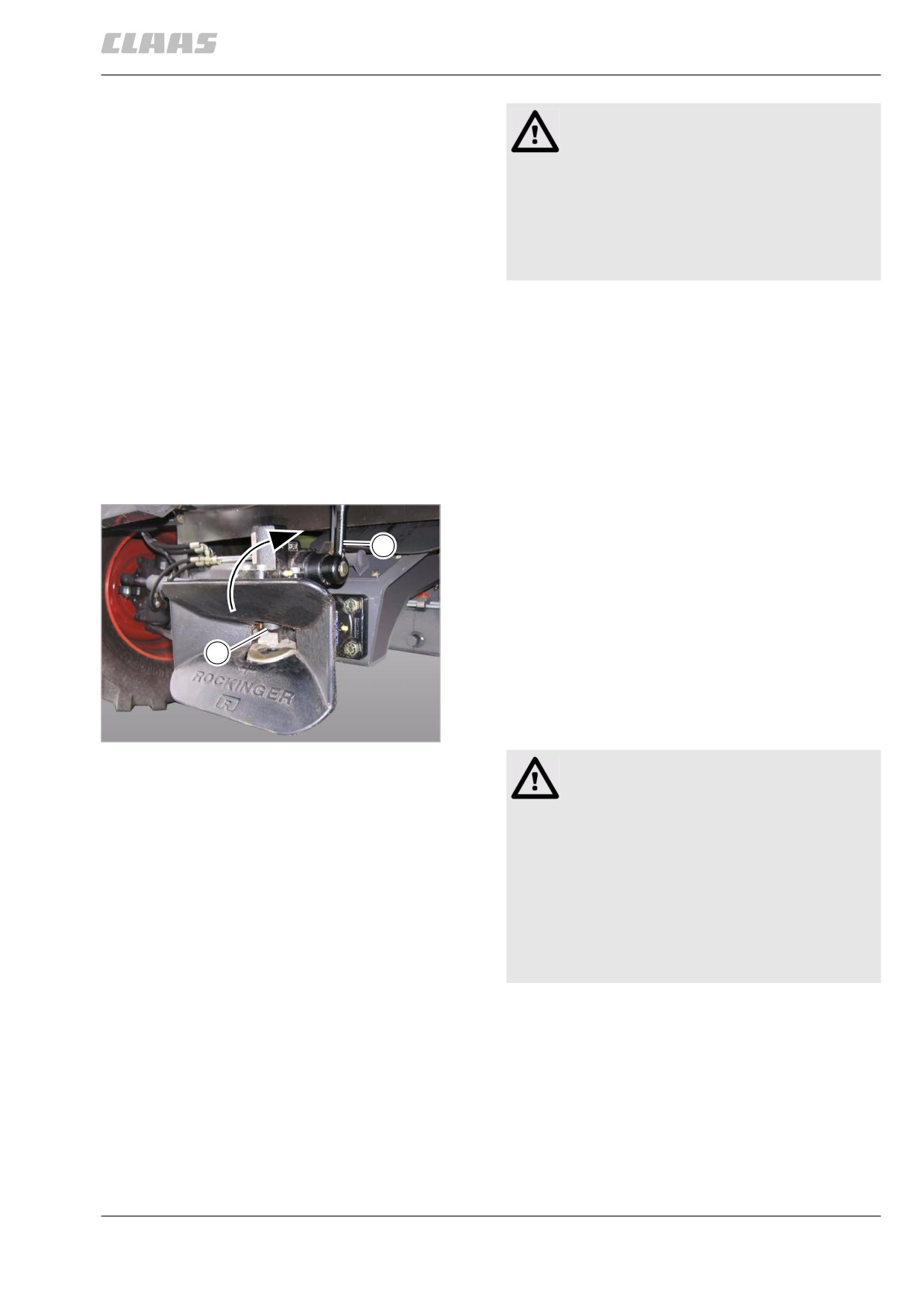
- Push down pawl (4) and push pin (5) into the
trailer hitch up to the stop (6).
- Release the pawl (4) and ensure that lock (7) has
engaged at the trailer hitch.
- Raise the trailer support wheel.
- Connect the power supply plug.
- If present, connect the breakaway cord to the
trailer hitch.
- Check the trailer lighting.
- If there is a braking system, carry out a brake test.
Type 841 ...
-
Secure the rear axle of the transport carriage so it
1
will not roll away.
-
If required, release the trailer steering axle brake.
The drawbar must be freely moving in all
directions.
With rigid-drawbar trailers, the hitch eye must hit
2
the centre of the hitch (2).
Failure to observe this rule will cause damage!
-
If required, set the hitch eyes to the height of the
coupling point.
49
Trailer hitch type 841 ...
19009
Danger!
Locking the trailer hitch by hand.
The locking pin shoots down.
Serious injuries of the limbs.
- Never lock the trailer hitch by hand by lift-
ing pin (2) (type 841).
- Lock trailer hitch exclusively with
lever (1), using a short blow with the ball
of the thumb in opening
direction (type 841).
-
Push the hand lever (1) up until it clicks.
–
Clean the trailer drawbar with a suitable agent.
–
Slowly back up the vehicle until the hitch eye has
tripped the trailer hitch lock.
163