CLAAS DOMINATOR 150 / 140 / 130. Operator’s Manual - page 8
7 Overview of controls
7.2 Cab / Operator's platform
67083
Danger!
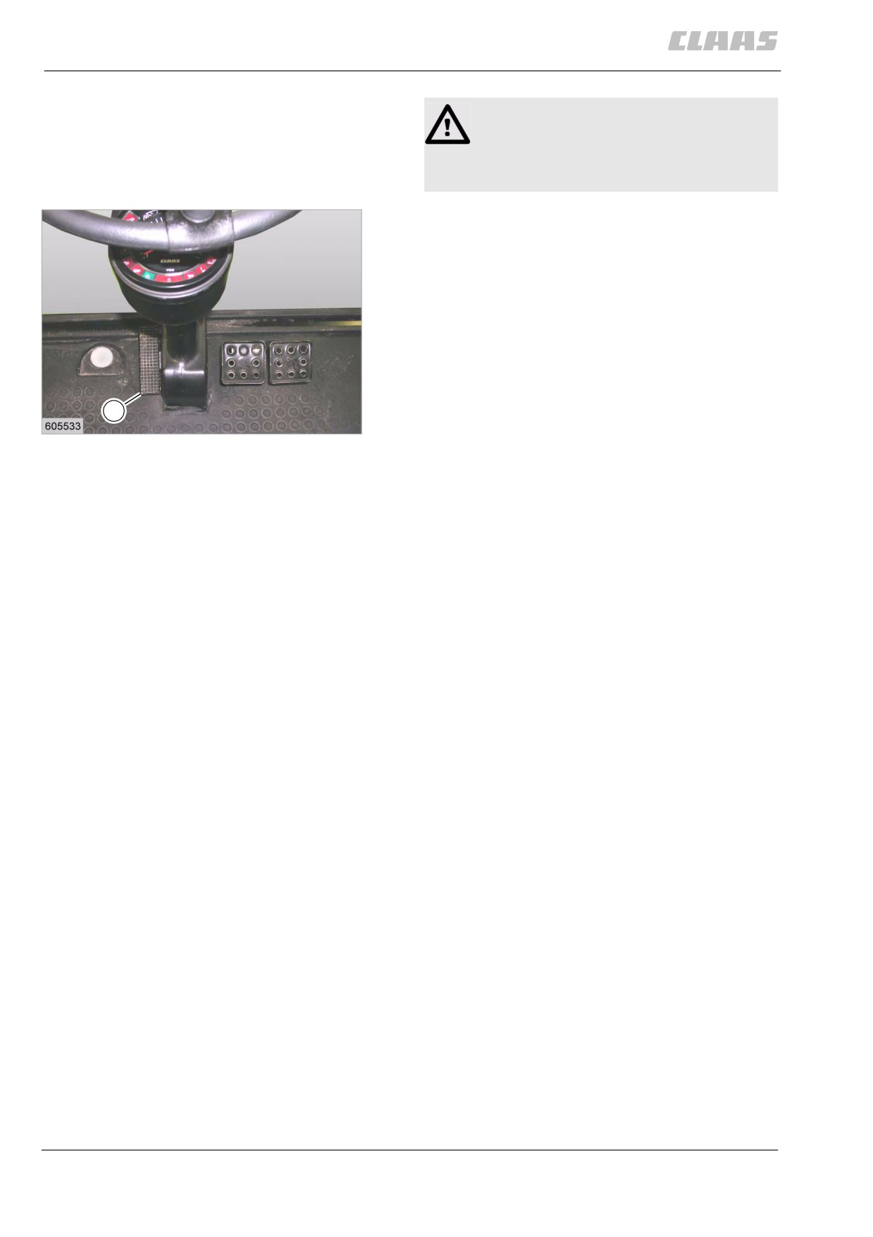
Never adjust the steering column whilst
driving!
Failure to do this may lead to injuries or death.
Pressing pedal (P) with your foot releases the lock of
the steering column for moving it to the desired
position.
P
15
19369
116
7 Overview of controls
7.2 Cab / Operator's platform
67083
79997
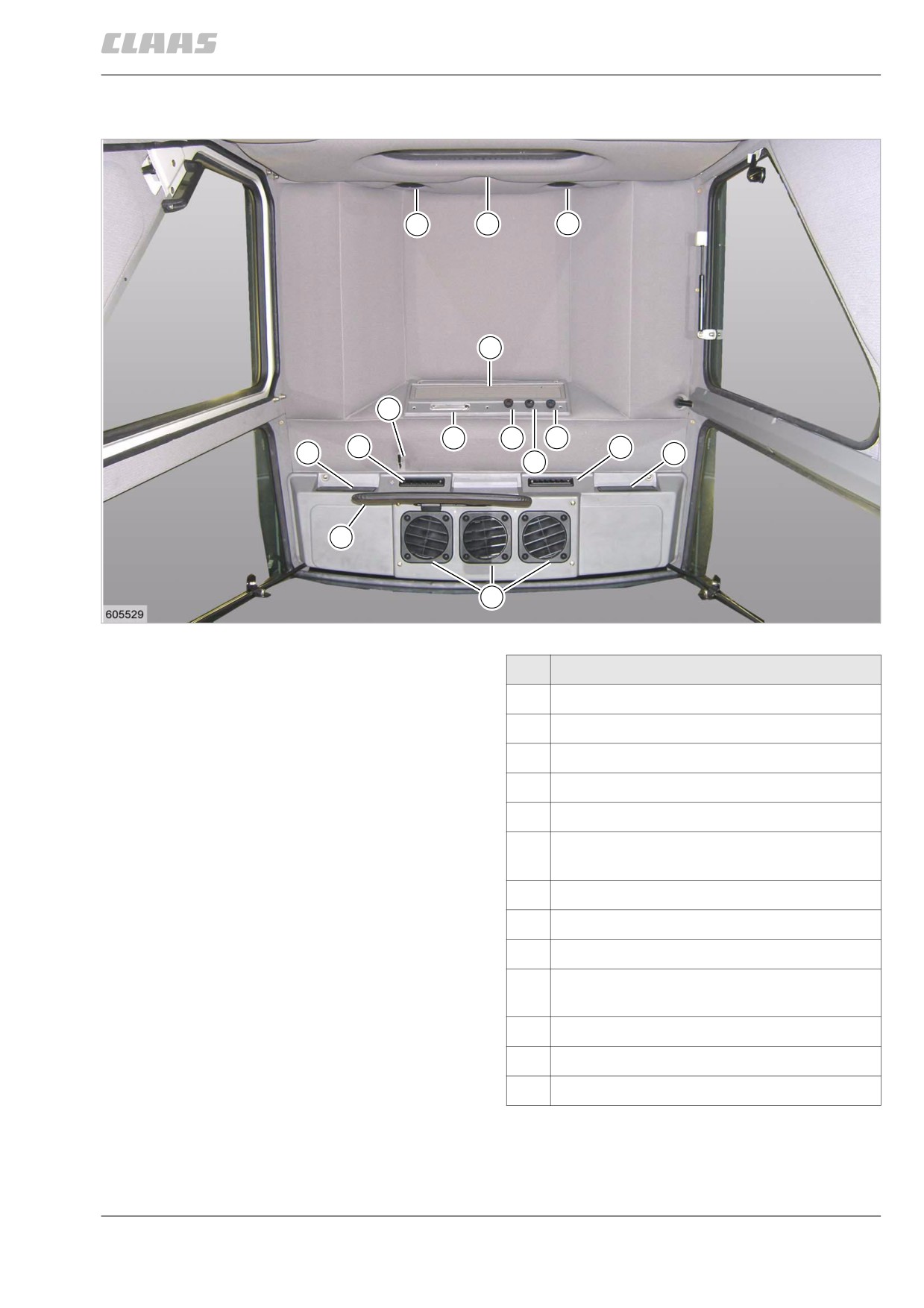
7.2.13 Cab roof controls
11
12
11
6
1
2
3
5
7
7
10
9
4
13
8
19295
16
Designation
1
Lever for bypass flap (cab with heater only)
2
Cab lighting with switch
3
Rotary knob for heater valve
4
Three-position switch for double fan
5
AC thermostat rotary switch
6
Air circulation grille (only in cabs equipped
with air conditioner)
7
Adjustable air louvres, can be closed
8
Adjustable air louvres
9
Storage compartment or space for CB radio
10
Storage compartment or space for broadcast
radio
11
Pressuriser fans
12
Press here to open cab roof
13
Sun visor
117
7 Overview of controls
7.2 Cab / Operator's platform
67083
54687
7.2.14 Cab with fan
The cab is equipped with an efficient double fan which
blows fresh air into the cab.
The fan can be set to three different speeds by means
of the 3-position switch (4).
Air louvres (7) and (8) allow the operator to control the
direction of air flow.
54693
7.2.15 Cab with air conditioner
(with York compressor)
Danger!
Contact with refrigerant.
Death or serious injury!
- Avoid any contact with refrigerant.
- If refrigerant splashes into the eyes, con-
sult a doctor immediately!
- Have maintenance and repair work car-
ried out by specialist air conditioning
system workshops only.
- Do not weld any components of the refrig-
erant circuit and in the immediate vicinity
of any parts of the refrigerant circuit. -
Danger of poisoning!
- Maximum ambient temperature for refrig-
erant is 80°C.
118
7 Overview of controls
7.2 Cab / Operator's platform
67083
Putting the air conditioner into operation (with
V
York compressor)
V
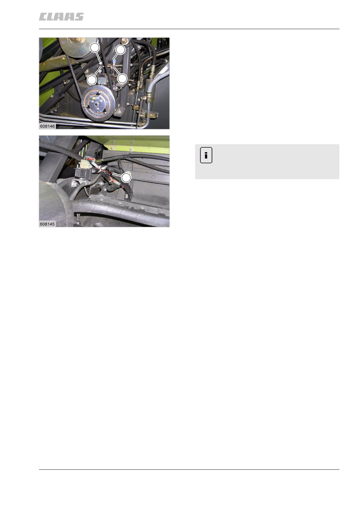
- Unscrew the seal caps of service valves at
(1 and 2).
- Completely open both service valves (1 and 2) to
1
2
their fully open position and tighten them in that
position so that the valve seating faces will seal off
properly toward the outside as well.
- Screw on the plugs of service valves at (1 and 2).
Ensure that the seal caps (V) are tight.
- Insert the flat fuse (F) (the cable with the flat fuse
17
(F) is located between the grain tank and the
19297
engine).
Caution!
The flat fuse (F) for the air conditioner must
never be inserted as long as the valves on the
compressor are closed.
F
18
19298
On cabs equipped with a cab heater, open the bypass
flap by moving lever (1) to the down position. Start the
diesel engine. Set the double fan to the desired speed
1 - 3 using switch (4). Turn air conditioner thermostat
switch (5) in clockwise direction to set the desired tem-
perature. The air conditioning system is now turned
on.
Precooled air from inside the cab is drawn in through
recirculating air grille (6) and mixed with filtered out-
side air. The blend is further cooled and pushed into
the cab through louvres (8) and (7). The adjustable air
louvres (8) and (7) allow the operator to control the
direction of air flow. Air louvres (7) can be closed, if
required.
When the desired temperature is reached, a thermo-
stat switch in conjunction with an electro-magnetic
clutch disengages the compressor.
The compressor is automatically engaged as the tem-
perature rises.
The air conditioner can only work properly if the door
and the windows are closed.
The air conditioner is shut down automatically if a mal-
function occurs:
The air conditioner was shut down via the high-pres-
sure switch.
119
7 Overview of controls
7.2 Cab / Operator's platform
67083
After the system has cooled down, the air conditioner
is switched on again automatically.
If the air conditioner is shut down very frequently at
very short intervals, it must be checked for any possi-
ble faults.
Possible causes - see Problem, possible cause and
remedy - Air conditioner.
Note!
Differences in temperature between the inside
air and outside air of more than 8 °C to 10 °C
(46 °F to 50 °F) are a danger to your health!
54708
7.2.16 Cab with air conditioner
(with Sanden compressor)
Danger!
Contact with refrigerant.
Death or serious injury!
- Avoid any contact with refrigerant.
- If refrigerant splashes into the eyes, con-
sult a doctor immediately!
- Have maintenance and repair work car-
ried out by specialist air conditioning
system workshops only.
- Do not weld any components of the refrig-
erant circuit and in the immediate vicinity
of any parts of the refrigerant circuit. -
Danger of poisoning!
- Maximum ambient temperature for refrig-
erant is 80°C.
The cab is equipped with an efficient fresh air fan.
The fan can be set to three different speeds by means
of the 3-position switch (4).
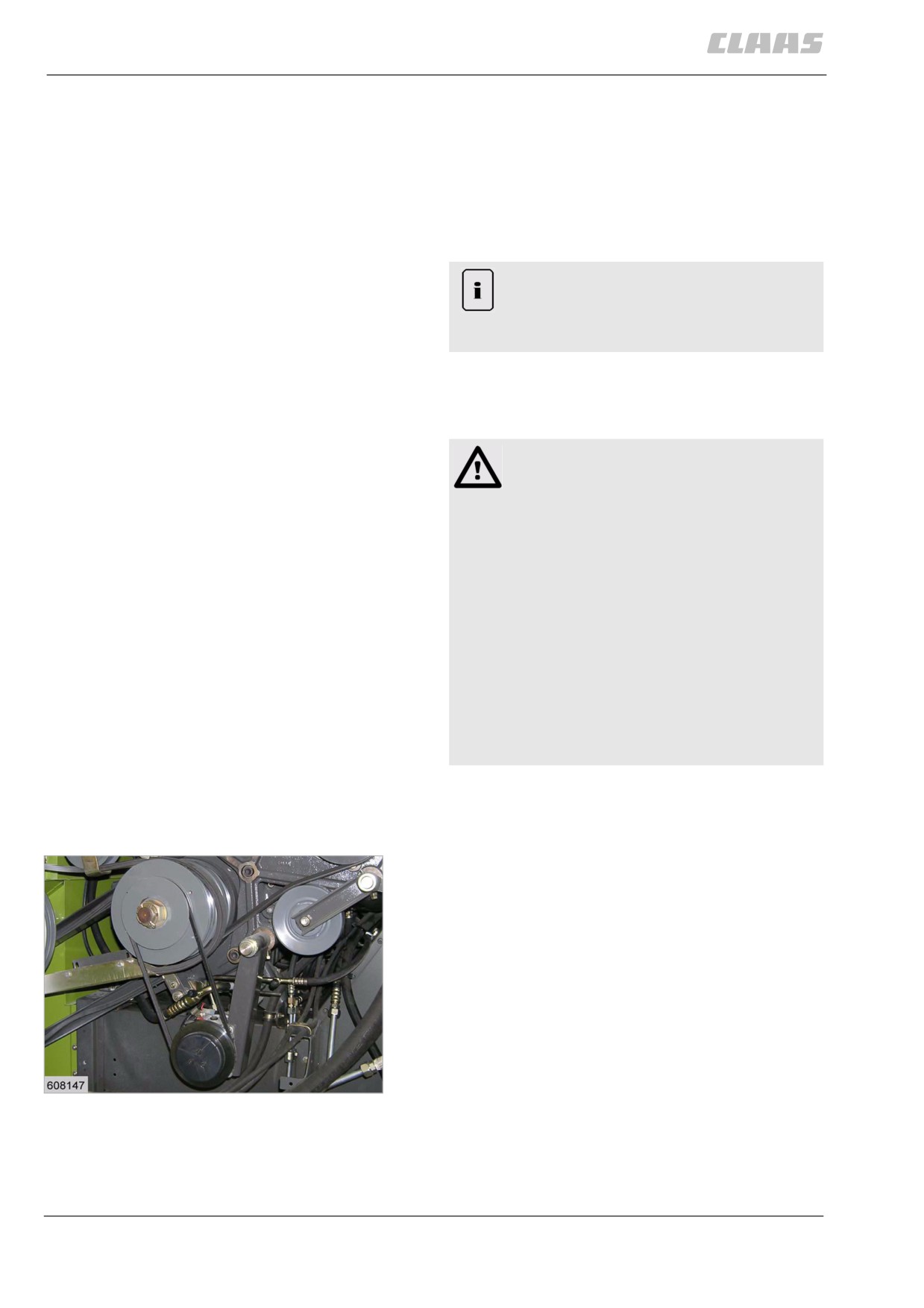
Putting the air conditioner into operation (with
Sanden compressor)
On cabs equipped with a cab heater, open the bypass
flap by moving lever (1) to the down position. Start the
diesel engine. Set the double fan to the desired speed
1 - 3 using switch (4). Turn air conditioner thermostat
switch (5) in clockwise direction to set the desired tem-
perature. The air conditioning system is now turned
on.
Precooled air from inside the cab is drawn in through
recirculating air grille (6) and mixed with filtered out-
19
side air. The blend is further cooled and pushed into
19303
the cab through louvres (8) and (7). The adjustable air
louvres (8) and (7) allow the operator to control the
direction of air flow. Air louvres (7) can be closed, if
required.
120
7 Overview of controls
7.2 Cab / Operator's platform
67083
When the desired temperature is reached, a thermo-
stat switch in conjunction with an electro-magnetic
clutch disengages the compressor.
The compressor is automatically engaged as the tem-
perature rises.
The air conditioner can only work properly if the door
and the windows are closed.
The air conditioner is shut down automatically if a mal-
function occurs:
The air conditioner was shut down via the high-pres-
sure switch.
After the system has cooled down, the air conditioner
is switched on again automatically.
If the air conditioner is shut down very frequently at
very short intervals, it must be checked for any possi-
ble faults.
Possible causes - see Problem, possible cause and
remedy - Air conditioner.
Note!
Differences in temperature between the inside
air and outside air of more than 8 °C to 10 °C
(46 °F to 50 °F) are a danger to your health!
54712
7.2.17 Cab with fan and heater
A hot water heating unit is installed downstream of the
fresh air fan.
The hot water flow rate through the heater coil and
thus the temperature of the heated air can be control-
led by means of turn switch (3).
Putting the heater into operation:
Open the taps on the engine. Close the bypass flap by
moving lever (1) to the up position. Turn switch (3) in
clockwise direction. The further the switch is turned to
the right, the higher the heating capacity. The adjusta-
ble air louvres (7) and (8) allow the operator to control
the direction of air flow (heated air and fresh air).
Clean the filters in the cab roof at regular intervals -
see cleaning the filters.
121
7 Overview of controls
7.2 Cab / Operator's platform
67083
54980
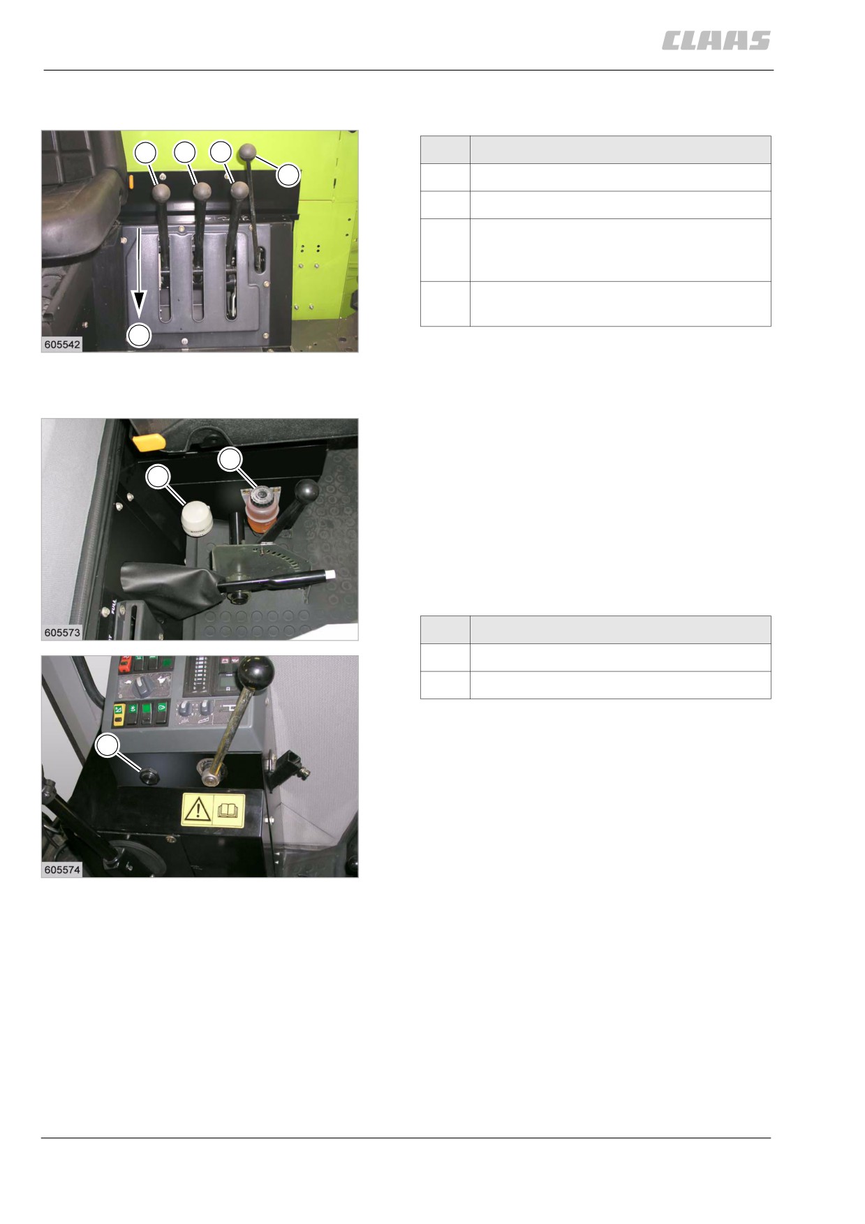
7.2.18 Control levers
1
2
3
Designation
4
1
Switches front attachment on and off
2
Switches threshing mechanism on and off
3
Engaging / disengaging grain tank unload-
ing Swinging the grain tank unloading tube
out / in
4
Swinging the grain tank unloading tube out /
in (DOMINATOR 130)
E
20
19419
54987
7.2.19 Functions monitor
The speed loss monitor monitors the speeds of the
upper feed rake shaft, clean grain and returns eleva-
B
tors, straw walker shafts and of the straw chopper. It
S
also monitors the air filter and the engine oil pressure.
The appropriate red indicator light in the combined
instrument gauge lights up and a buzzer sounds when
shaft speed slows down, when the air filter is soiled
and when the engine oil pressure is too low. The
buzzer (S) located on the right-hand side of the opera-
tor's seat goes on and off intermittently.
21
Designation
DOMINATOR 130
19428
S
Buzzer
B
Brake fluid reservoir
S
22
DOMINATOR 150 / 140
19430
122
7 Overview of controls
7.2 Cab / Operator's platform
67083
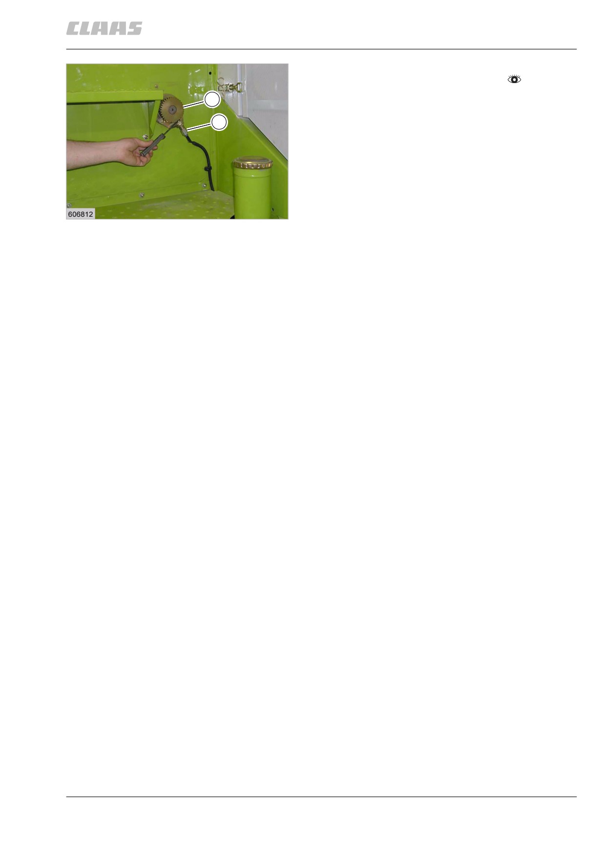
- Observe the general warnings at the beginning of
the "Overview of controls" chapter.
Z
All magnetic pick-ups (J) must be set to a gap of 1 ±
0.5 mm between gear wheels (Z) and the magnetic
J
pick-up.
When the engine is being started, the buzzer sounds
briefly until the engine oil pressure has built up.
The shaft speed-loss monitors are switched on and off
by means of a switch that is activated by the cutterbar
drive control mechanism.
23
19431
123
7 Overview of controls
7.3 Attachment parts / machine body
67083
7.3 Attachment parts / machine body
54990
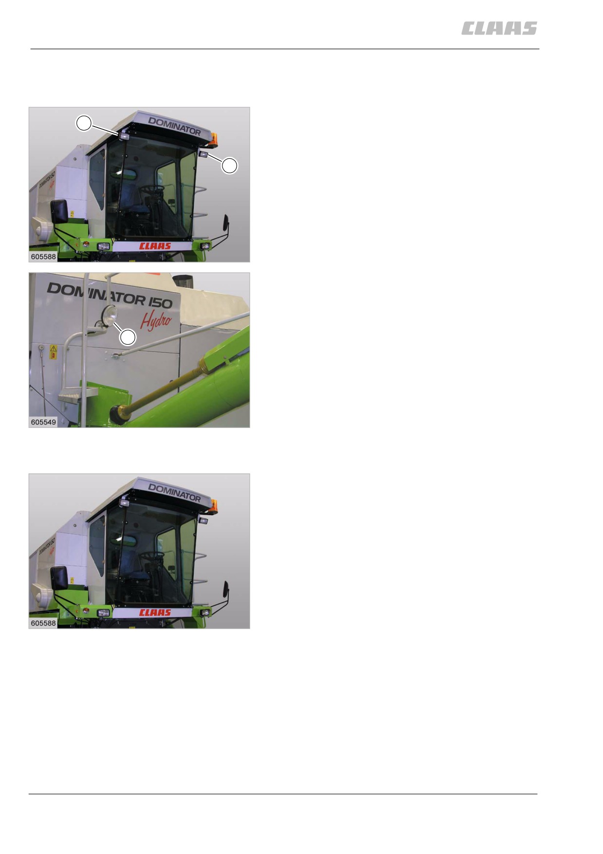
7.3.1 Worklights
Two worklights (A) on the railing of the operator's plat-
A
form or on the front frame of the operator's cab and
one worklight (B) on the left side of the grain tank allow
the combine to be operated even in the dark.
A
24
19433
B
25
19434
54991
7.3.2 Cab
As an option, the machine can be equipped with an
operator's cab in one of four versions.
• Cab with fan
• Cab with fan and heater
• Cab with fan and air conditioner
• Cab with fan, heater, and air conditioner
These variants make operation of the combine far
more comfortable for the operator even under the most
unfavourable weather conditions (dust, heat or cold).
26
19433
124
7 Overview of controls
7.3 Attachment parts / machine body
67083
54992
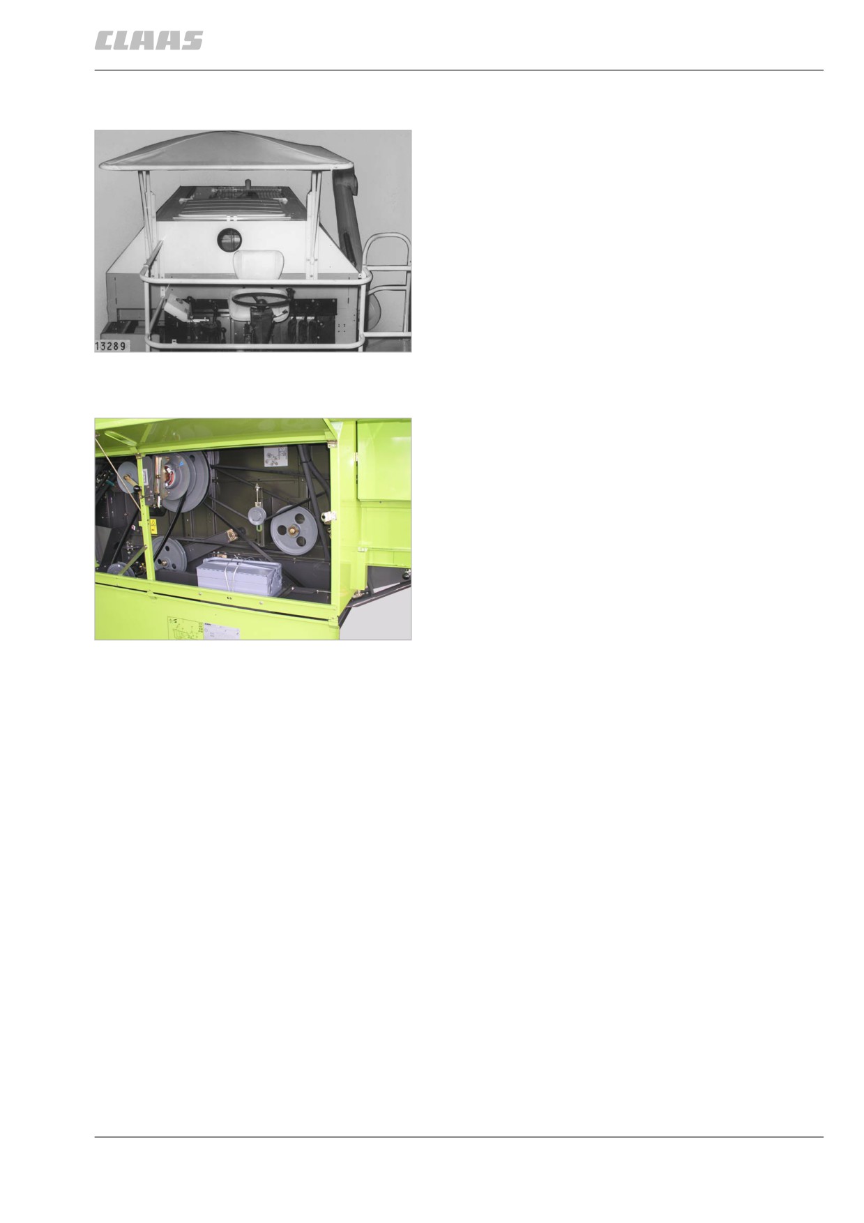
7.3.3 Sun roof
As an option, the machine can be equipped with a sun
roof. The height of the sun roof is adjustable.
27
19435
81986
7.3.4 Tool box
The tool box with on-board tools can be found behind
the doors on the left machine side.
The tool box is secured by a wire rope. The lock is
located at position (1).
28
28347
125
8 Mounting/removing front attachment
8.1 General Information
67084
8 Mounting/removing front attachment
8.1 General Information
38920
8.1.1 General warnings Installing / removing
the front attachment
In the following sections of this chapter, a procedure
instruction refers to the following general warnings.
Danger!
Moving machine parts and / or unexpected
machine movements.
Death or serious injury.
- Advise everyone to leave the hazard
area.
Danger!
The front attachment, reel and feeder unit may
drop uncontrolled.
Death or serious injuries!
- Apply safety locks.
- Keep a safe distance from the hazard
area.
126
8 Mounting/removing front attachment
8.2 Installing the front attachment
67084
8.2 Installing the front attachment
70747
8.2.1 Suspending front attachment
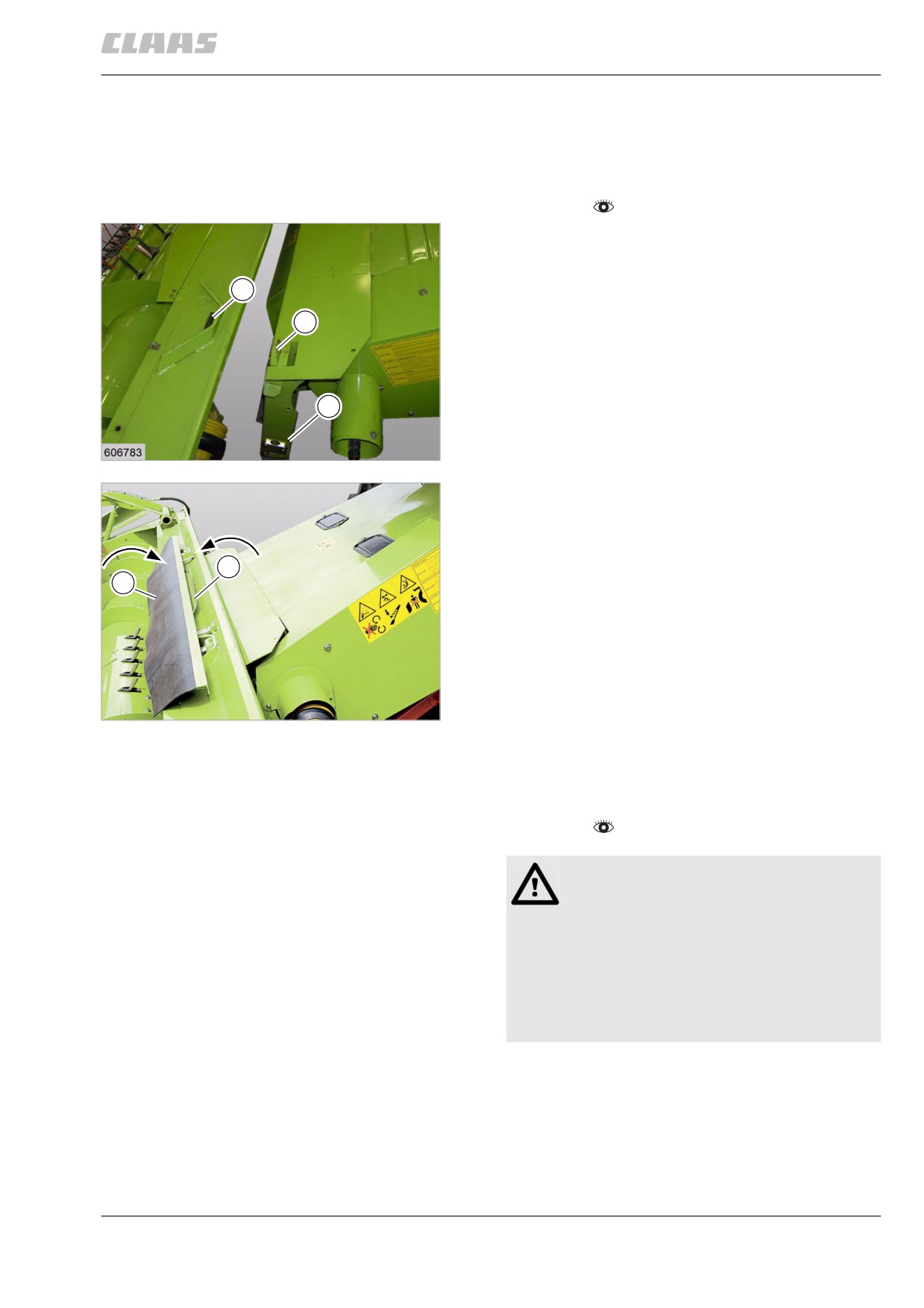
- Observe the general warnings at the beginning of
the Fitting / removing the front attachment
chapter.
- Fitting / adjusting mounting plates (3)
- On machines fitted with AUTO-CONTOUR sys-
tem, align the coupling lug (1) with the front
2
attachment.
- Slowly approach the front attachment with the
1
machine until the coupling lug (1) is positioned
beneath the pockets (2).
- Raise the front attachment with the feed rake
conveyor.
3
- Apply the parking brake of the machine and stop
the engine.
1
19522
- If provided, swing rubber blanket (1) over and
place it on the feed rake conveyor.
- If provided, swing plate (2) over the intake auger.
2
1
2
24848
70751
8.2.2 Interlocking the front attachment
- Observe the general warnings at the beginning of
the Fitting / removing the front attachment
chapter.
DANGER!
The front attachment is not sufficiently
secured.
Death or serious injury.
- Comply precisely with procedure
instructions.
- Check the safe locking of the front
attachment.
127
8 Mounting/removing front attachment
8.2 Installing the front attachment
67084
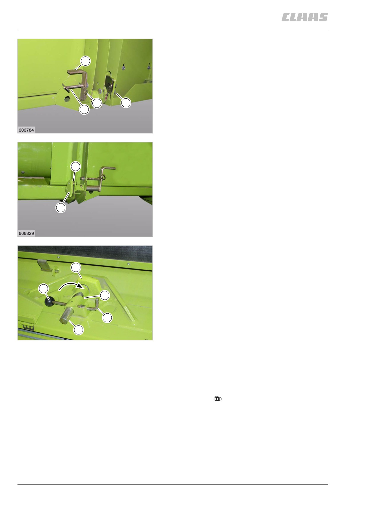
- Pull out cotter pin (1) at (A).
- Slide lock pin (2) up into the opening of the feed
rake conveyor of the machine, using lever (3).
3
- Secure lever (3) in this position, using a cotter
pin (1).
1
2
A
3
19523
- Checking / adjusting stop plates.
- Install shims (1) on both sides between the stop
plates (2) and the cutterbar frame and adjust
1
the stop plates so that there is no lateral tension
on the feed rake conveyor from either side.
2
4
19524
only front attachments and machines equipped
with AUTO-CONTOUR:
4
- Swing lever (1) up to position (A).
- Ensure that locking pin (2) engages in the bore of
peg (4) of the machine.
1
- Ensure that locking pin (2) is secured against
A
twisting by locking pin (3).
3
2
5
24849
- Repeat this procedure on the other side of the
machine.
70765
8.2.3 Installing universal drive shaft
- Observe the general warnings at the beginning of
the Fitting / removing the front attachment
chapter.
128
8 Mounting/removing front attachment
8.2 Installing the front attachment
67084
1
Danger!
Rotating universal drive shafts.
Death or serious injury.
- Check for secure latching of the locks or
locking pins.
- Never operate universal drive shaft with-
2
out protective guard.
- Replace defective protective guards on
the universal drive shaft immediately.
- Observe the recommendations of the
6
DOMINATOR
19526
drive shaft manufacturer.
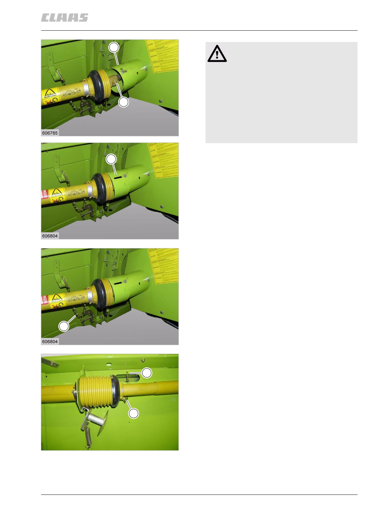
- Push back or swing up protective guard (1),
1
depending on the version.
- Push in the locking pin (2).
Slide universal drive shaft onto the drive pin.
- Pull out or fold down protective guard (1), depend-
ing on the version.
7
DOMINATOR
19527
- Turn universal drive shaft in such a manner that
the chain (1) does not wrap around the universal
drive shaft more than 90°.
If necessary, cut off excess length of the chain (1)
or hang chain (1) so that it is shorter.
1
8
DOMINATOR
19527
- Hang chain (1) on the bracket (2).
- Turn universal drive shaft in such a manner that
2
the chain (1) does not wrap around the universal
drive shaft more than 90°.
If necessary, cut off excess length of the chain (1)
or hang chain (1) so that it is shorter.
1
9
24170
129
8 Mounting/removing front attachment
8.2 Installing the front attachment
67084
70769
8.2.4 Connecting the hydraulic system
- Observe the general warnings at the beginning of
the Fitting / removing the front attachment
chapter.
1
Caution!
Machine operation with polluted utilities.
Machine damage.
- Ensure that no dirt will get into the
removed lines.
- Ensure a clean environment.
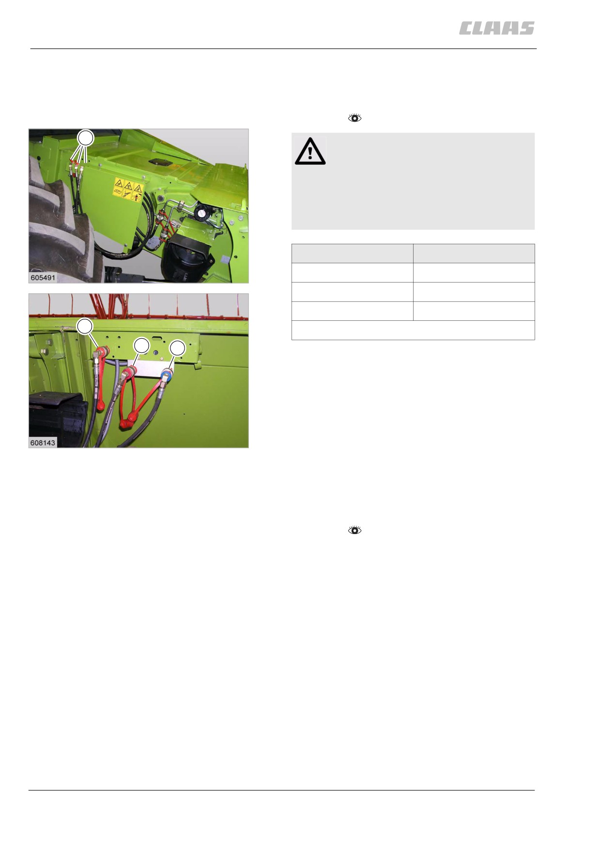
Connection
Colour
A
colourless
10
14540
B *
red
C *
blue
A
* (accessory)
B
C
- Connect the male couplings with a colour
marking (1) to the corresponding female
couplings (A/B/C).
11
19528
70791
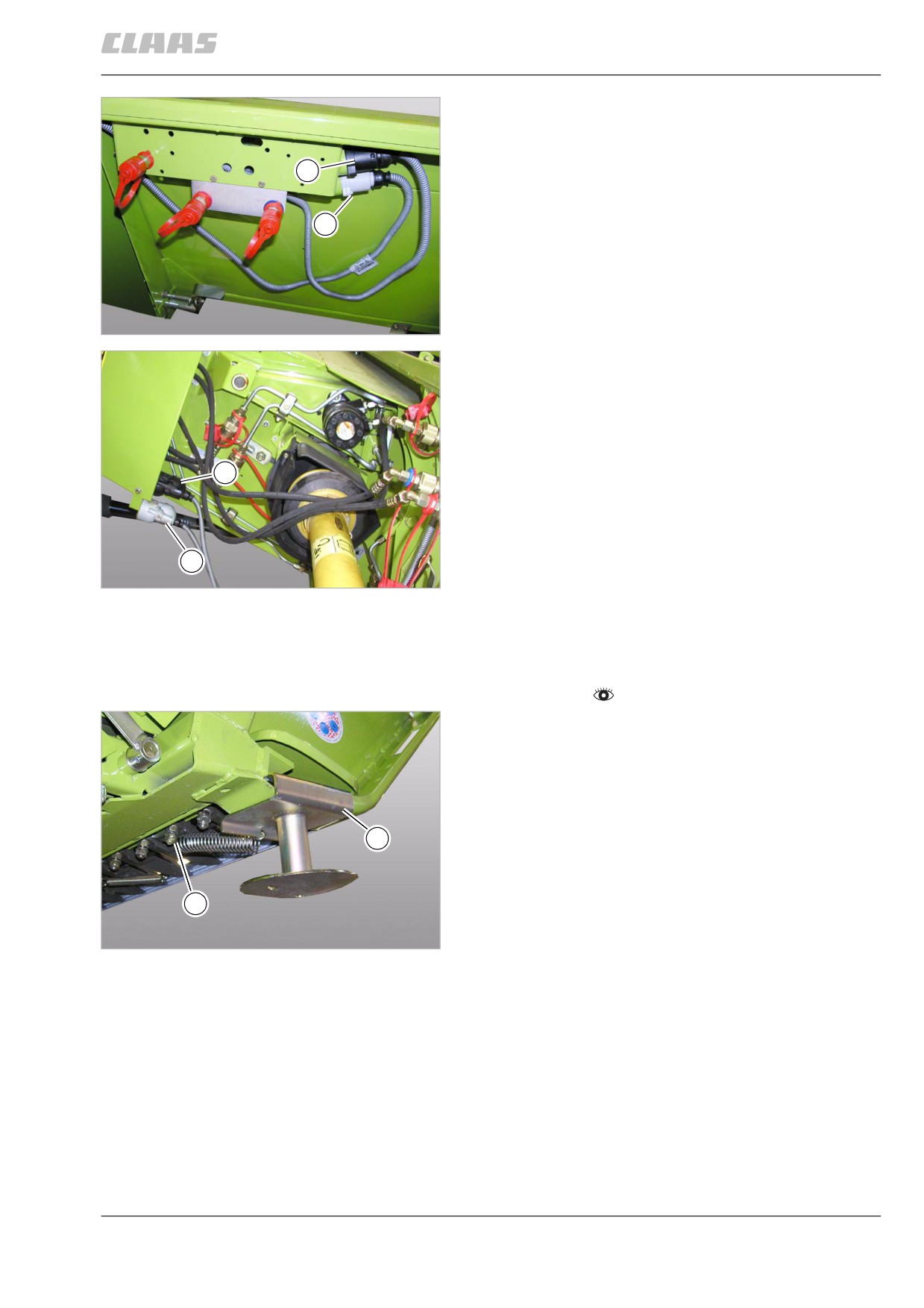
8.2.5 Connecting the electric equipment
(accessory)
- Observe the general warnings at the beginning of
the Fitting / removing the front attachment
chapter.
130
8 Mounting/removing front attachment
8.2 Installing the front attachment
67084
- Plug connector (1) into socket (2).
- Plug connector (3) into socket (4).
1
3
12
24274
2
4
13
24275
71387
8.2.6 Removing the stands
- Observe the general warnings at the beginning of
the Fitting / removing the front attachment
chapter.
- Loosen spring at (1).
- Remove stand (2) from the base frame.
- Repeat this process on the other side of the front
attachment.
2
1
14
17304
131