CLAAS DOMINATOR 150 / 140 / 130. Operator’s Manual - page 6
4 Specifications
4.1 DOMINATOR 150 / 140 / 130
67080
72296
4.1.15 Cleaning unit
Designation
DOMINATOR
Fan
•
•
•
paddle-type cleaning fan
Fan adjustment
•
•
•
mechanical
Preparation floor
•
•
•
removable
3-D cleaning system
•
•
•
(optional equipment)
Sieve separating area
•
•
•
3.00 m2
72299
4.1.16 Grain delivery
Designation
DOMINATOR
Returns
•
•
•
returned to threshing drum
Grain tank capacity
4000 litres (approx. 3.1 metric tons of
•
wheat)
basis for calculation in t = litre weight of 780 g/l
3200 litres (approx. 2.5 metric tons of
•
•
wheat)
72313
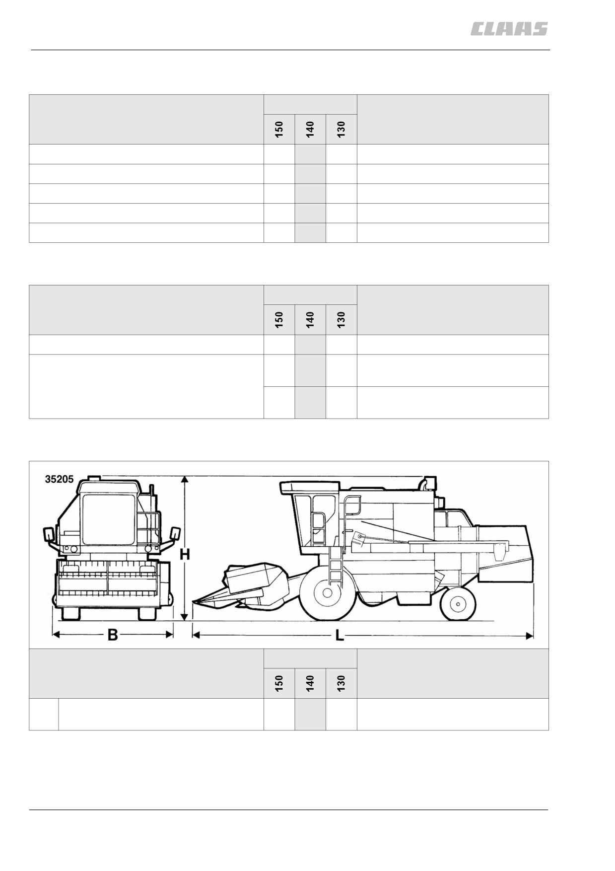
4.1.17 Attachment parts / machine body dimensions
Designation
DOMINATOR
B
Width of the body (machine width with
3000 mm
•
•
•
tyres - see chassis wheel track)
84
4 Specifications
4.1 DOMINATOR 150 / 140 / 130
67080
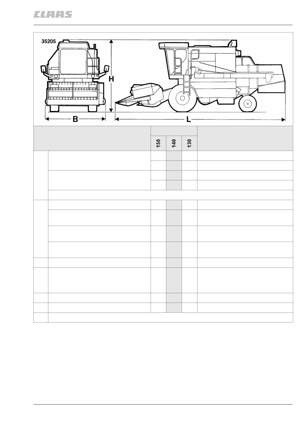
Designation
DOMINATOR
H
Height, up to top edge of air filter suction
•
•
3850 mm*
screen, grain tank closed
•
3840 mm*
Height up to upper edge of grain tank,
•
•
4100 mm*
open
•
4080 mm*
* Height determined with 18.4 - 30 12 PR and 11.5/80 - 15.3 6 PR tyres
L
Length, feed rake conveyor to tailgate
•
•
•
7200 mm**
Length, feed rake conveyor to straw chop-
7400 mm**
•
•
•
per protective cover
Length, feed rake conveyor to straw
8020 mm**
•
•
•
spreader safety frame
Length, feed rake conveyor up to straw
8050 mm**
•
•
•
collector
Wheel base
•
•
•
3335 mm
Ground clearance (up to elevator boot)
435 mm**
•
•
•
Deviations of up to ±50 mm possible,
depending on the tyre manufacturer.
Left turning circle diameter DIN 70020
•
•
•
15150 mm
Right turning circle diameter DIN 70020
•
•
•
15250 mm
** (Height of bottom edge of feed rake conveyor 500 mm)
85

4 Specifications
4.1 DOMINATOR 150 / 140 / 130
67080
72306
4.1.18 Attachment parts / machine body weights
Designation
DOMINATOR
Empty weight *
•
7330 kg
•
•
7250 kg
Chopper weight
•
•
•
+ 290 kg
Straw spreader
•
•
•
+ 97 kg
Straw collector
•
•
•
+ 235 kg
* Empty weight without cutterbar, chopper and chaff spreader, with full fuel tank
86
5 Prior to initial operation
5.1 General Information
67081
5 Prior to initial operation
5.1 General Information
37391
5.1.1 General warnings Prior to initial
operation
In the following sections of this chapter, a procedure
instruction refers to the following general warnings.
Danger!
Always stop the engine before carrying out
any work on the machine.
Moving machine parts and / or unexpected
machine movement.
Death or serious injury.
- Diesel engine OFF.
- Apply parking brake.
- Remove the ignition key.
- Remove key of battery isolating
switch.
- Wait for machine parts which run on have
come to a complete halt.
- Secure machine by wheel chocks.
- Ensure that the machine cannot be
started by any third persons.
Danger!
The front attachment, reel and feeder unit may
drop uncontrolled.
Death or serious injuries!
- Apply safety locks.
- Keep a safe distance from the hazard
area.
79390
5.1.2 Initial operation check list
The following must be done before putting the
machine into operation.
- Complete all necessary items on the checklist for
daily putting the machine into operation.
- Observe instructions for loading and tying down
the machine.
- After sea transport or road transport in winter road
conditions, clean the machine to protect it from
salt damage.
Engine
- Check the correct seat of air filter.
- Check the diesel engine oil level.
- Check the radiator coolant level.
87
5 Prior to initial operation
5.1 General Information
67081
Chassis
- Fit the wheels.
- Check the tyre pressure and correct if necessary.
- Check condition and permissibility of tyres.
- If necessary adjust the rear axles / rear wheel
drive axles from transport position to working
position.
- If necessary adjust the wheel track for the given
tyres.
- Check tightening values of wheel fixing elements
and correct if necessary.
- Check oil level in all gearboxes and refill if
necessary.
Brake
- Check brake fluid level and top up if required.
Drives
- Check all belt tensions and adjust if necessary.
- Check all safety guards and put them into their
correct position, if required.
- Check oil level in all gearboxes and top up if
necessary.
Hydraulic system
- Check hydraulic oil level and tightness of hydrau-
lic system.
Electrical / electronic equipment
- Fill and charge battery, if required.
- Install fan / air conditioner fuse.
- If necessary, install side lights in case of excess
width.
Intake
- Remove the lift eyes.
- Fit mounting plates.
- Check the front attachment float springs.
- Align the coupling lugs (machines without Auto-
Contour)
Separation
- Remove the lift eyes.
Grain delivery
- Close the service aperture on the grain tank
unloading tube.
- Install the grain tank safety device.
- Putting the air conditioner into operation (with
Sanden compressor)
88
5 Prior to initial operation
5.2 Chassis
67081
5.2 Chassis
89352
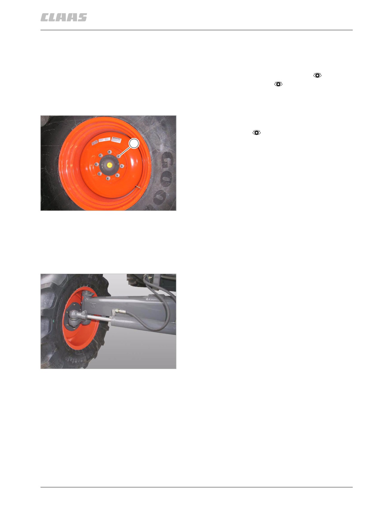
5.2.1 Removing / installing the wheels
- Observe the general warnings at the beginning of
the Prior to initial operation chapter.
- Jack up the machine.
- Remove / install wheel.
Ensure that large tyres cannot tip over, if neces-
sary use a carriage.
- After fitting the wheel, tighten all wheel nuts /
wheel bolts (1) to the specified tightening torque
as instructed.
1
1
9617
79223
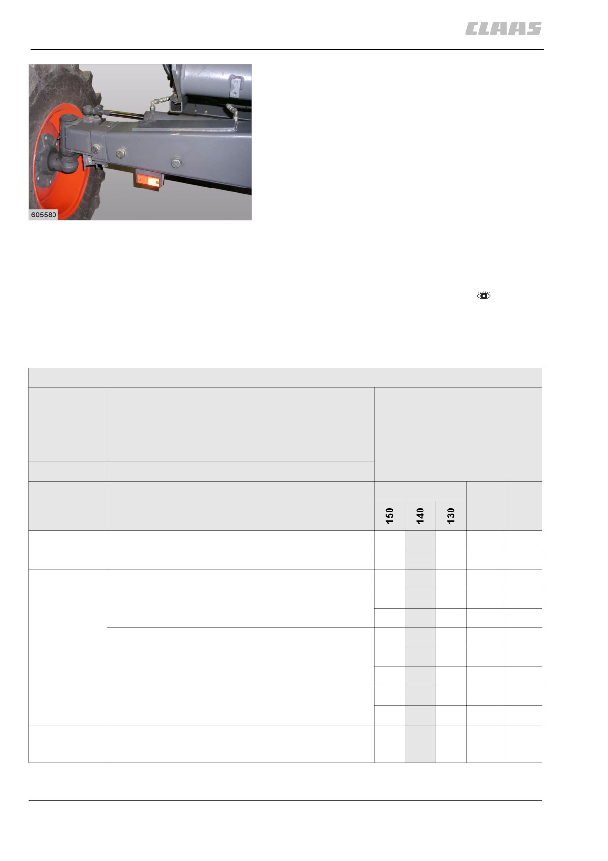
5.2.2 Overview of rear axle
Either one or several different types of rear axles are
available.
The part number for identifying the rear axle is pro-
vided on the identification plate of the axle.
Rear axle
00 0770 350 1
2
27215
89
5 Prior to initial operation
5.2 Chassis
67081
Rear axle
00 0649 950 1
3
19471
79317
5.2.3 Converting the rear axle
from transport to working position
- Observe the general warnings at the beginning of
the Prior to initial operation chapter.
The following installation steps must be carried out,
depending on the tyres used on the rear axles
00 0637 630 2, 00 0649 950 1 and 00 0770 350 1:
See table of rear axle positions.
Rear axle position
LA-P
Rear axle position,
1 = bottom hole,
2 = top hole,
3 = rear axle rise (rice)
FW
Flange width
Tyres
DOMINATOR
LA-P
FW
(mm)
Rear axle
11.5/80-15.3 IMP
•
•
•
1
2040
00 0637 630 2
12.5/80-18 IMP (320/80-18)
•
•
•
2
2040
Rear axle
11.5/80-15.3 IMP
•
•
•
1
2291
00 0649 950 1
•
•
•
1
2491
•
•
•
1
2691
12.5/80-18 IMP (320/80-18)
•
•
•
2
2291
•
•
•
2
2491
•
•
•
2
2691
14.5/75-20 IMP(360/80-20)
•
•
•
2
2291
•
•
•
2
2491
Rear axle
9.5-24 R1
3
2391
•
00 07703501
90
5 Prior to initial operation
5.2 Chassis
67081
WARNING:
The tyres may collide with the vehicle body.
Damage to tyres and vehicle body.
- Adjust track width to the tyres used.
- Adjust the rear axle position of the central
axle pivot pin with the axle. See table of
rear axle positions
Danger!
Jacking up the machine.
Death or serious injury.
- Use jack / jack stand with sufficient
capacity.
- Use reliable jack / jack stand.
- Use jack / jack stand on solid and level
ground.
- Apply the jack / jack stand at the position
of the machine intended for this purpose.
-
Suspend the machine in the lift eyes at the rear
and lift it (see loading and tying down the
2
machine) until the rear axle wheels have only
slight ground contact.
-
Securely underpin axle against lowering and tip-
ping over.
1
-
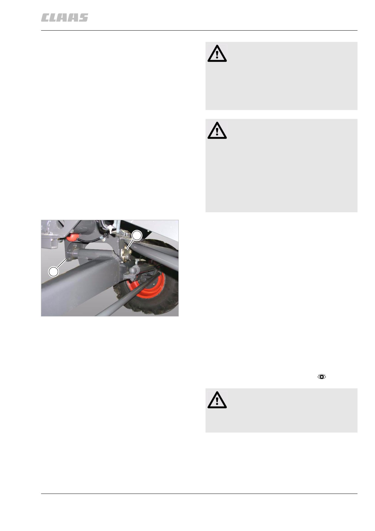
Unscrew flat bar (2) and pull out pin (1).
–
Raise or lower machine.
–
Insert pin (1) into the bottom or top hole and bolt
down flat bar (2). For rear axle rise (rice) see rice
threshing equipment.
4
27234
-
If necessary, adjust rear wheel drive
axle 00 0649 950 1 wheel track.
79261
5.2.4 Rear axle 00 0649 950 1 - Adjusting the
track width
- Observe the general warnings at the beginning of
the Prior to initial operation chapter.
Warning:
The tyres may collide with the vehicle body.
Damage to tyres and vehicle body.
- Adjust track width to the tyres used.
The track width depends on the flange width (F) to be
set and on the tyres.
The axle can be set to three different flange widths.
91
5 Prior to initial operation
5.2 Chassis
67081
Danger!
1
Jacking up the machine.
Death or serious injury.
- Use jack / jack stand with sufficient
3
capacity.
- Use reliable jack / jack stand.
- Use jack / jack stand on solid and level
ground.
2
- Apply the jack / jack stand at the position
of the machine intended for this purpose.
5
19471
-
Jack up the machine a little at the rear until the
rear axle wheels only have slight ground
contact.
-
Remove the right-hand ball joint of the track rod.
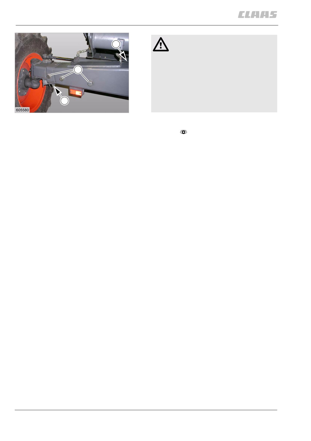
–
Remove steering cylinder mounting bracket (1)
from the axle body.
-
Slacken off the clamping bolts (2) on both sides.
–
Unscrew mounting bolts (3) on both sides.
–
Slide the adjustable axle sections in or out to
obtain the desired track width (2300 mm, 2500
mm, 2700 mm). Install mounting bolts (3), but do
not tighten them at this time.
-
Tighten clamping bolts (2) first, then tighten
mounting bolts (3).
-
Bolt down mounting bracket (1) in the correspond-
ing tapped holes.
-
Set the wheels to zero toe-in by adjusting the
right-hand ball joint on the track rod. In order to
obtain accurate measurements, measure from the
inside edges of the rim, where the beading of the
tyres rests. Secure the track rod. Use new self-
locking nuts. Tightening torque = 140 Nm
92
5 Prior to initial operation
5.3 Hitch
67081
5.3 Hitch
102219
5.3.1 Installing the trailer hitch (accessories)
- Observe the general warnings at the beginning of
the Prior to initial operation chapter.
1
Danger!
Improper mounting of the trailer hitch.
Death or serious injuries!
3
- Note the prescribed tightening torque for
the trailer hitch.
2
4
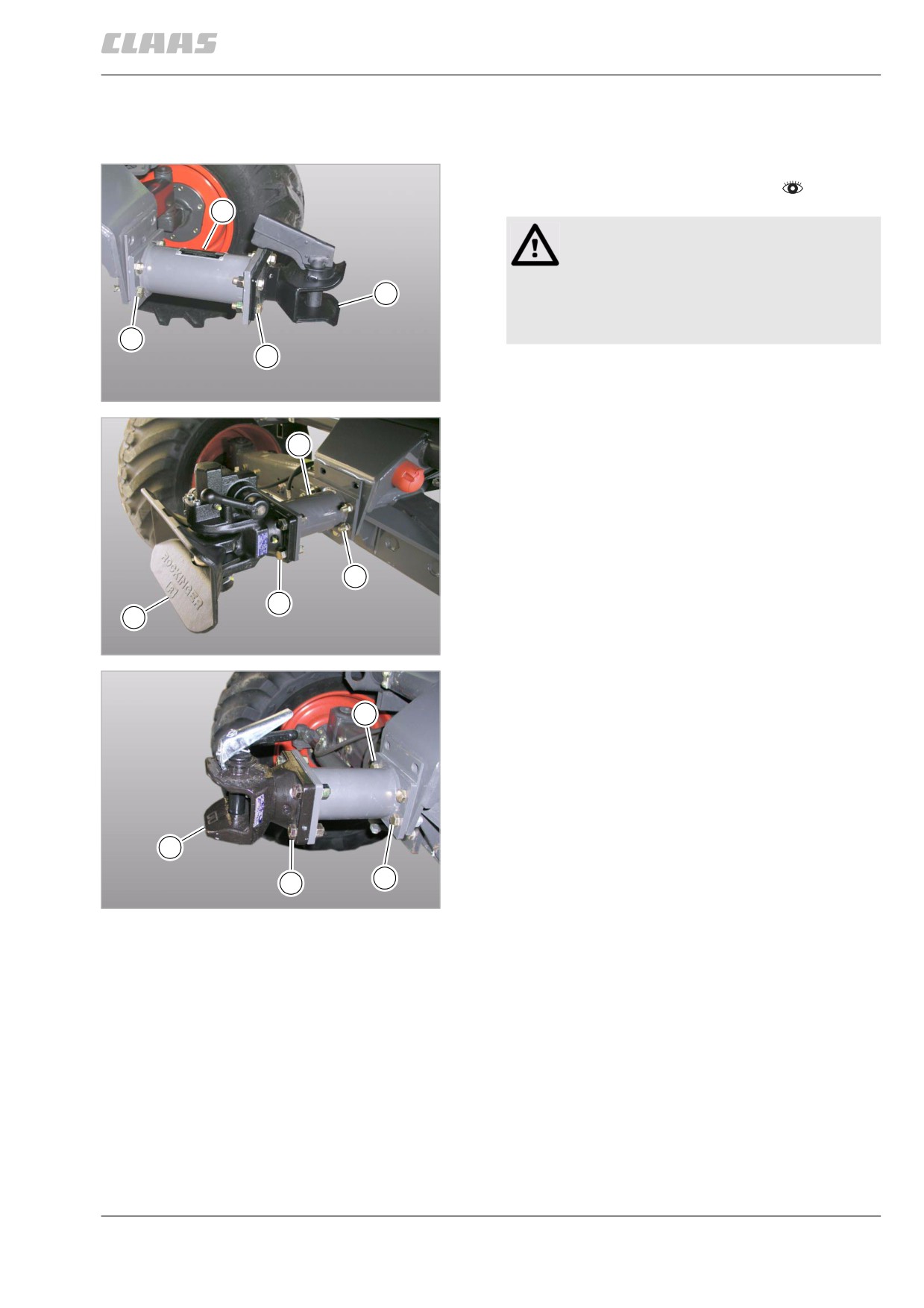
- Bolt down hitch block (1) with bolts (2).
The bolt heads must point to the rear.
6
Trailer hitch type AK 64/1 B ...
24699
Tightening torque M14 = 133 Nm
- Bolt down trailer hitch (3) with bolts (4). The bolt
1
heads point to the rear.
Tightening torque M16 = 207 Nm
- If required, bolt down the bracket for the cutterbar
trailer brake system tear-off cord to bolt (4).
2
4
3
7
Trailer hitch type 841 ...
36440
1
3
2
4
8
Trailer hitch type 810 ...
40022
93
5 Prior to initial operation
5.4 Electrical / electronic equipment
67081
5.4 Electrical / electronic equipment
59400
5.4.1 Installing the fan / air conditioner fuse
The fan / air conditioner fuse is enclosed as a pack
joint (cab) on machines with an air conditioner in order
to prevent compressor damage.
- Install fan / air conditioner fuse.
- Put the air conditioner into operation.
94
5 Prior to initial operation
5.5 Feeder unit
67081
5.5 Feeder unit
79358
5.5.1 Fitting / adjusting the mounting plates
-
Observe the general warnings at the beginning of
the Prior to initial operation chapter.
DANGER!
The front attachment is not sufficiently
secured.
Death or serious injury.
- Comply precisely with procedure
instructions.
- Check the safe locking of the front
attachment.
-
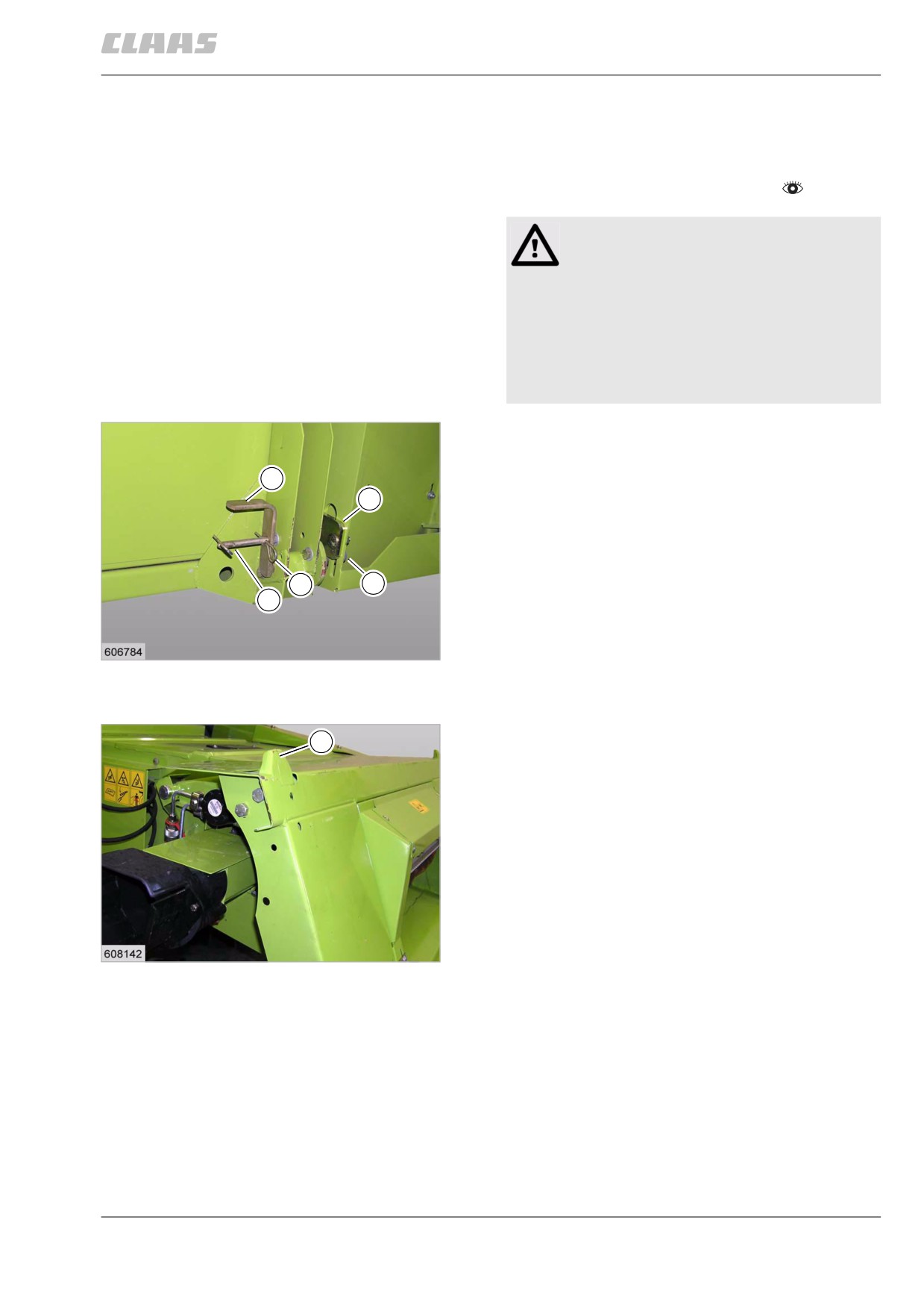
Bolt down mounting plate (4) hand-tight on both
sides of the machine.
-
Fit front attachment.
3
–
Pull out cotter pin at position (A).
4
–
Slide lock pin (2) up into the feeder unit opening of
the machine, using lever (3).
-
Secure lever (3) in position (B), using the cotter
pin.
B
2
-
Slacken off mounting plate (4) and slide it as
A
closely to the lock pin (2) as possible. Bolt down
mounting plate (4).
9
19523
89422
5.5.2 Aligning the coupling pin
The front attachment must be parallel with the drive
F
axle of the machine. To achieve this, the coupling pins
must be aligned.
- Drive the machine with the front attachment fitted
on a flat and level surface.
- Check the alignment. The finger bar must be par-
allel with the ground while the machine stands on
a flat and level surface.
- If necessary, put down the front attachment.
- Slacken off coupling pins (1) and raise or lower
the pins so that the finger bar is parallel with the
10
ground on a flat and level surface.
19525
95
5 Prior to initial operation
5.5 Feeder unit
67081
79492
5.5.3 Checking the front attachment cylinders
- Observe the general warnings at the beginning of
the Prior to initial operation chapter.
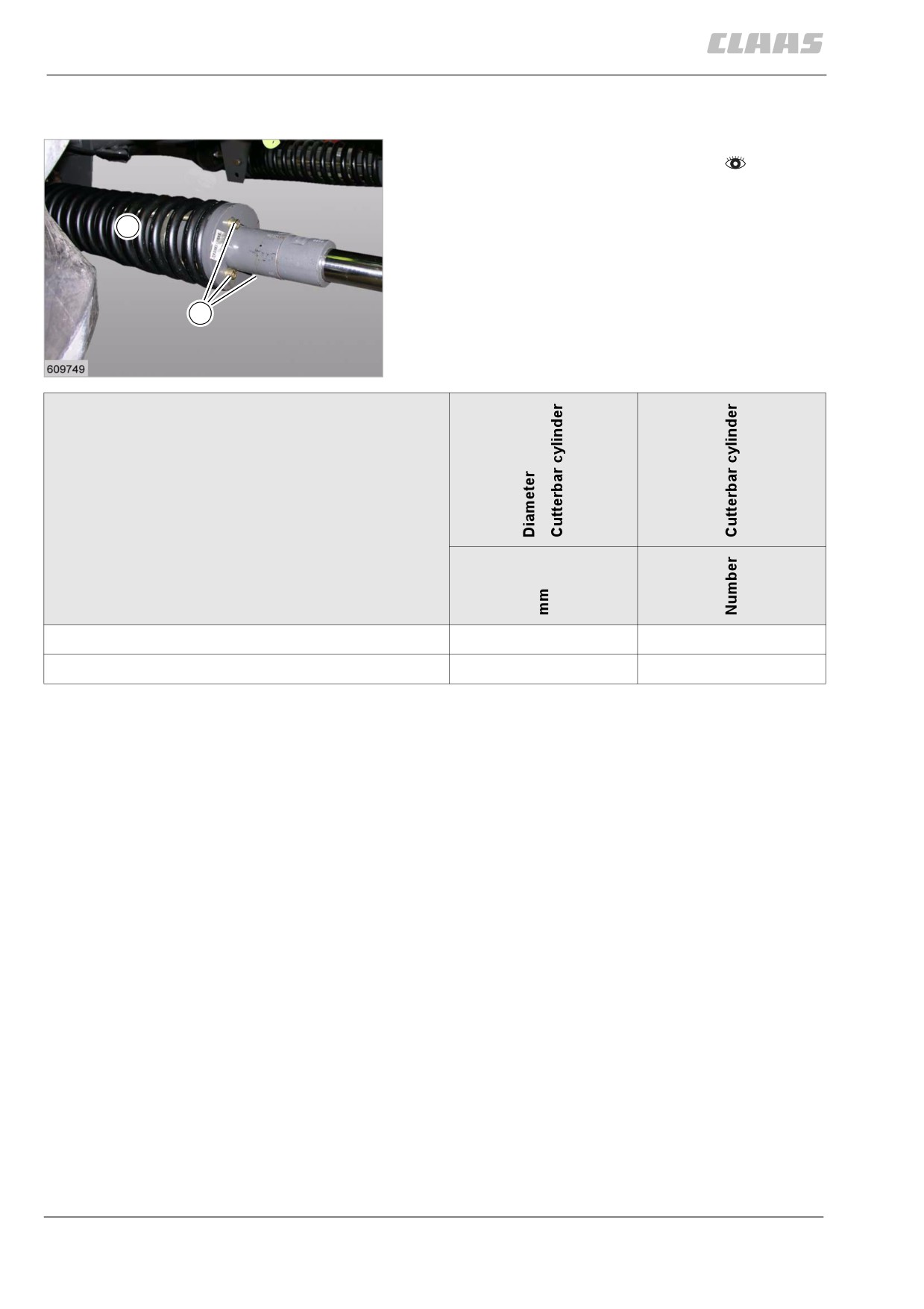
The front attachment cylinders (1) are fitted ex works
to suit the ordered front attachment width. When
1
changing the front attachment width at a later date, the
cylinder diameter must be checked / adapted.
3
11
19598
Number of cutterbar cylinders
Dominator 130 / 140 / 150
Cutterbar 3.05 m - 4.57 m
45
2
Cutterbar 5.18 m - 6.09 m
55
2
96
5 Prior to initial operation
5.5 Feeder unit
67081
73259
5.5.4 Checking the cutterbar float springs
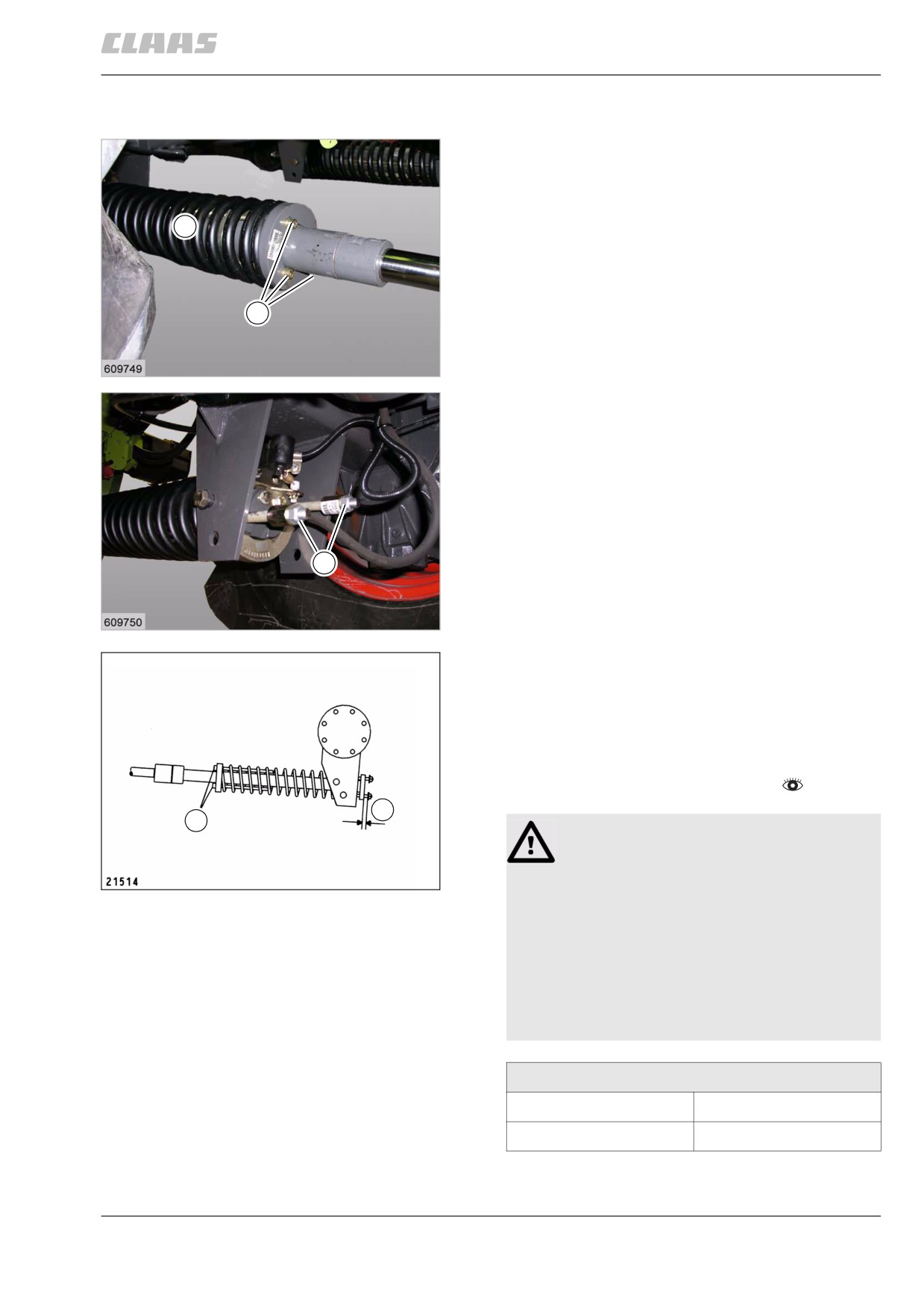
The cutterbar float springs (1) are pre-set ex works.
The cutterbar float springs (1) must be checked and
adjusted with the front attachment fitted.
- Fit the front attachment.
1
- Fit the crop dividers.
- Lower the cutterbar until the skids are about 100
mm above the ground.
3
12
19598
2
13
19599
The distance (Y) between the coupling pin cylinder
plate and the nuts should be 5 mm.
- Adjust the cutterbar float springs if required.
- To do this, adjust the cutterbar float springs
accordingly at the socket head bolts (2).
- Observe the general warnings at the beginning of
the Prior to initial operation chapter.
Y
2
Danger!
Bolts may break when tilting the spring plates.
14
Death or serious injuries!
19600
- Ensure that the tilted position of the
spring plate near the bolt pitch circle
diameter may be 1 mm max.
- Grease bolt threads.
- Now turn the bolts in or out by
3 revolutions each (5 mm) max., one
after the other.
Adjusting the bolts (2):
Increasing the distance
Turn bolts in
Reducing the distance
Turn bolts out
97
5 Prior to initial operation
5.5 Feeder unit
67081
- Check adjustment after changing the front attach-
ment and readjust if required.
98
5 Prior to initial operation
5.6 Grain delivery
67081
5.6 Grain delivery
79443
5.6.1 Closing the service aperture on the grain
tank unloading tube
- Observe the general warnings at the beginning of
the Prior to initial operation chapter.
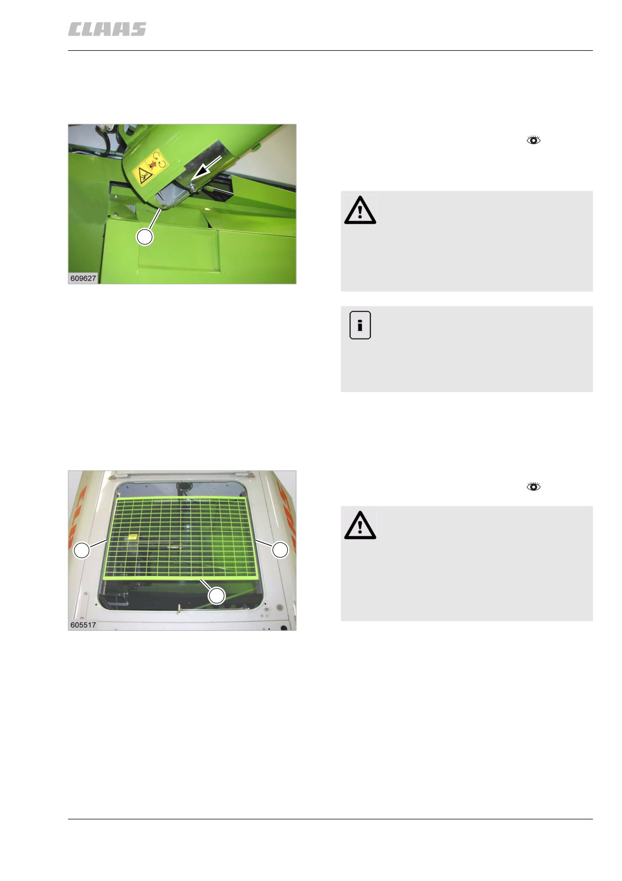
The service aperture on the grain tank unloading tube
serves as a water drain, e.g. for cleaning.
Warning!
Sharp edges and pointed machine parts.
1
Slight injuries.
- Do not touch sharp edges of the auger
flights.
15
- Wear safety gloves.
19660
Note!
Open service aperture.
Trickling losses.
- Close the service aperture and screw in
bolt (1).
- Close the service aperture and screw in bolt (1)
before putting the machine into operation for the
first time.
83027
5.6.2 Installing the grain tank safety device
- Observe the general warnings at the beginning of
the Prior to initial operation chapter.
Danger!
Danger of falling!
2
2
Death or serious injuries!
- Arrange for additional safety precautions.
- Only enter areas protected by railings.
1
- Areas originally without railings must be
protected by additional railings.
16
10456
- Open the grain tank cover and fold it open to the
rear as far as possible.
- Install safety device (1) into the rails (2).
99