Extra 500. Maintenance Manual (2012) - page 17
Table of Contents
73-00-00
GENERAL
3
73-30-00
Indicating
........................................................................................................... 3
Description.......................................................................................................... 3
73-30-01
Fuel Pressure Transducer
................................................................................ 3
Description.......................................................................................................... 3
Removal/Installation
........................................................................................... 3
73-30-02
Low Fuel Pressure Switch
................................................................................ 4
Description.......................................................................................................... 4
Removal/Installation
........................................................................................... 4
Page 2 73
73-00-00
GENERAL
For specific repair and replacement information refer to Rolls-Royce 250-B17F
Series Engine Operation and Maintenance Manual (LOAP 1).
73-30-00
Indicating
Description
The fuel indication consists of fuel pressure and a low fuel pressure warning in
the annunciator panel. The fuel pressure indication is described in 77-40-02
73-30-01
Fuel Pressure Transducer
Description
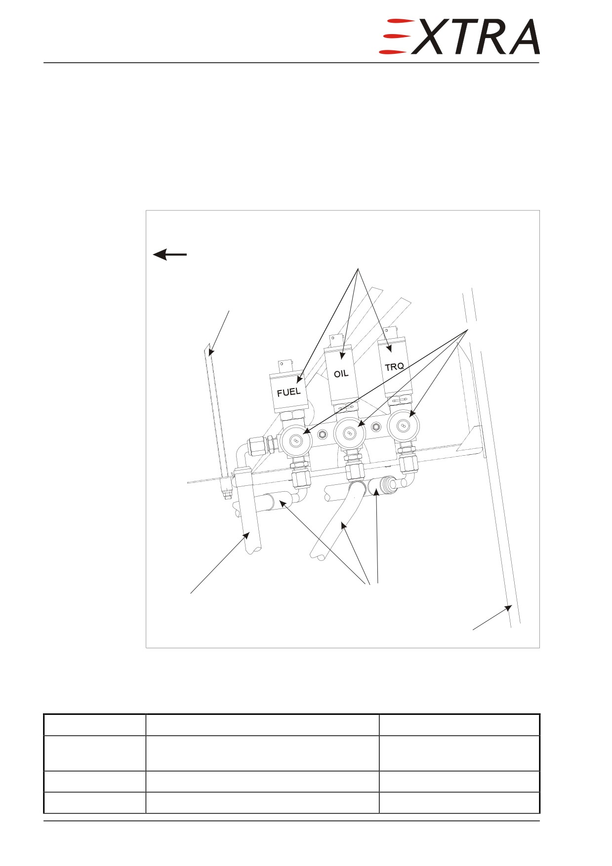
The fuel pressure transducer is located in the engine compartment, in the
sensor block mounted on the LH side of the battery mount, the most forward
upper sensor (refer to Figure 77-1).
Removal/Installation
Detail Steps/Work Items
Key Items
1
Ensure BATT switch is OFF and no external
power connected.
2
Remove LH upper cowling.
Refer to Chapter 71-10-01
3
Disconnect electrical connector.
Fuel may be pressurized (30 psi max). Fuel may spill. Protect yourself
WARNING
and catch spilling fuel in a suitable container.
4
Remove transducer from fuel pressure
manifold.
5
Install in reverse sequence of removal.
Replace O-ring when
necessary.
73 Page 3
73-30-02
Low Fuel Pressure Switch
Description
The low fuel pressure switch is located in the engine compartment, in the
sensor block mounted on the LH side of the battery mount, the most forward
sideward sensor (refer to Figure 79-1).
Removal/Installation
Detail Steps/Work Items
Key Items
1
Ensure BATT switch is OFF and no external
power connected.
2
Remove LH upper cowling.
Refer to Chapter 71-10-01
3
Disconnect electrical connector.
Fuel may be pressurized (30 psi max). Fuel may spill. Protect yourself
WARNING
and catch spilling fuel in a suitable container.
Never force the body of the sensor to turn against friction. It may
CAUTION
change the set-point. Always use a key on the attachment fitting for
removal and installation
4
Remove sensor.
5
Install in reverse sequence of removal.
Page 4 73
Chapter 74
Ignition
74 Page 1
74-00-00
GENERAL
Ignition on the EXTRA 500 is only needed at engine start. For safety reasons it
is also switched on at take-off and landing and in severe weather conditions
(heavy rain, icing etc). The ignition switch is integrated in the start switch
(refer to Chapter 80-00-00).
For specific repair and replacement information refer to Rolls-Royce 250-B17F
Series Engine Operation and Maintenance Manual (LOAP 1).
74 Page 3
Chapter 76
Engine Controls
76 Page 1
Table of Contents
76-00-00
GENERAL
3
Description.......................................................................................................... 3
Rigging Check
.................................................................................................... 3
Figure 76-1
Engine Control Lever Travel Schematic
4
76-10-00
POWER CONTROL
........................................................................................ 5
76-10-01
Engine Control Mounting Bracket
5
Description.......................................................................................................... 5
Removal/Installation
........................................................................................... 5
Figure 76-2
Engine Control Mounting Bracket
6
76-10-02
Throttle Quadrant
............................................................................................ 7
Description.......................................................................................................... 7
Removal
.............................................................................................................. 7
Installation
.......................................................................................................... 8
76-10-03
Power Lever Bowden Cable............................................................................. 8
Description.......................................................................................................... 8
Removal
.............................................................................................................. 8
Installation
.......................................................................................................... 9
76-10-04
Condition Lever Bowden Cable
.................................................................... 10
Description........................................................................................................ 10
Removal
............................................................................................................ 10
Installation
........................................................................................................ 10
Page 2 76
76-00-00
GENERAL
For specific repair and replacement information refer to Rolls-Royce 250-B17F
Series Engine Operation and Maintenance Manual (LOAP 1).
Description
The EXTRA 500 engine is controlled with two levers located in the middle
console: The power lever and the condition lever. Two Bowden cables are
routed through the firewall to the engine coordinator.
On the engine control mounting bracket, two microswitches are mounted. The
upper microswitch signals that the engine fuel is shut-off and has the function
to shut-off the bleed air when the engine is shut down. The lower is connected
to the LOW PITCH caution light on the annunciator panel.
Rigging Check
Detail Steps/Work Items
Key Items
1
Remove LH upper cowling.
Refer to Chapter 71-10-01
2
Perform engine manufacturer prepared
Refer to Rolls-Royce 250-
rigging check.
B17F Series Engine
Operation and Maintenance
Manual (LOAP 1), Chapter
76-00-00, page 201.
3
Check that the upper microswitch switches
Adjust by bending the
2-3 mm before the cut-off position is
microswitch arm
reached.
4
Check that the lower microswitch switches
Adjust by bending the
the LOW PITCH caution light on at 37°-39°
microswitch arm
(as indicated on the engine coordinator)
moving to a lesser angle.
76 Page 3
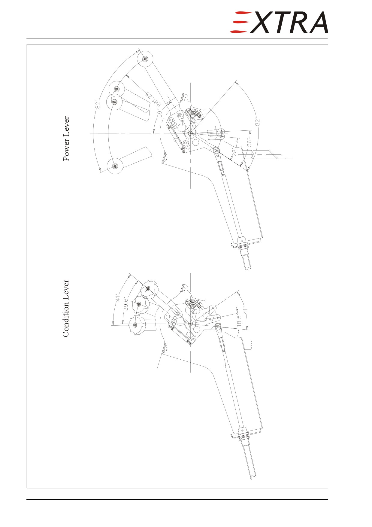
Figure 76-1
Engine Control Lever Travel Schematic
Page 4 76
76-10-00
POWER CONTROL
76-10-01
Engine Control Mounting Bracket
Description
The engine control mounting bracket is installed on the engine coordinator and
holds both engine control Bowden cables and 2 microswitches (refer to Figure
76-2).
Removal/Installation
Detail Steps/Work Items
Key Items
1
Remove LH upper cowling.
Refer to Chapter 71-10-01
2
Disconnect electrical wiring of the
microswitches.
3
Remove the Bowden cable rod ends from
the engine control levers.
4
Remove Bowden cables from bracket
flange.
5
Remove the two side supports of the
2 screws
bracket.
6
Remove the bracket.
2 screws
7
Install in reverse sequence of removal.
8
Perform engine control rigging check.
Refer to Subject 76-00-00
76 Page 5
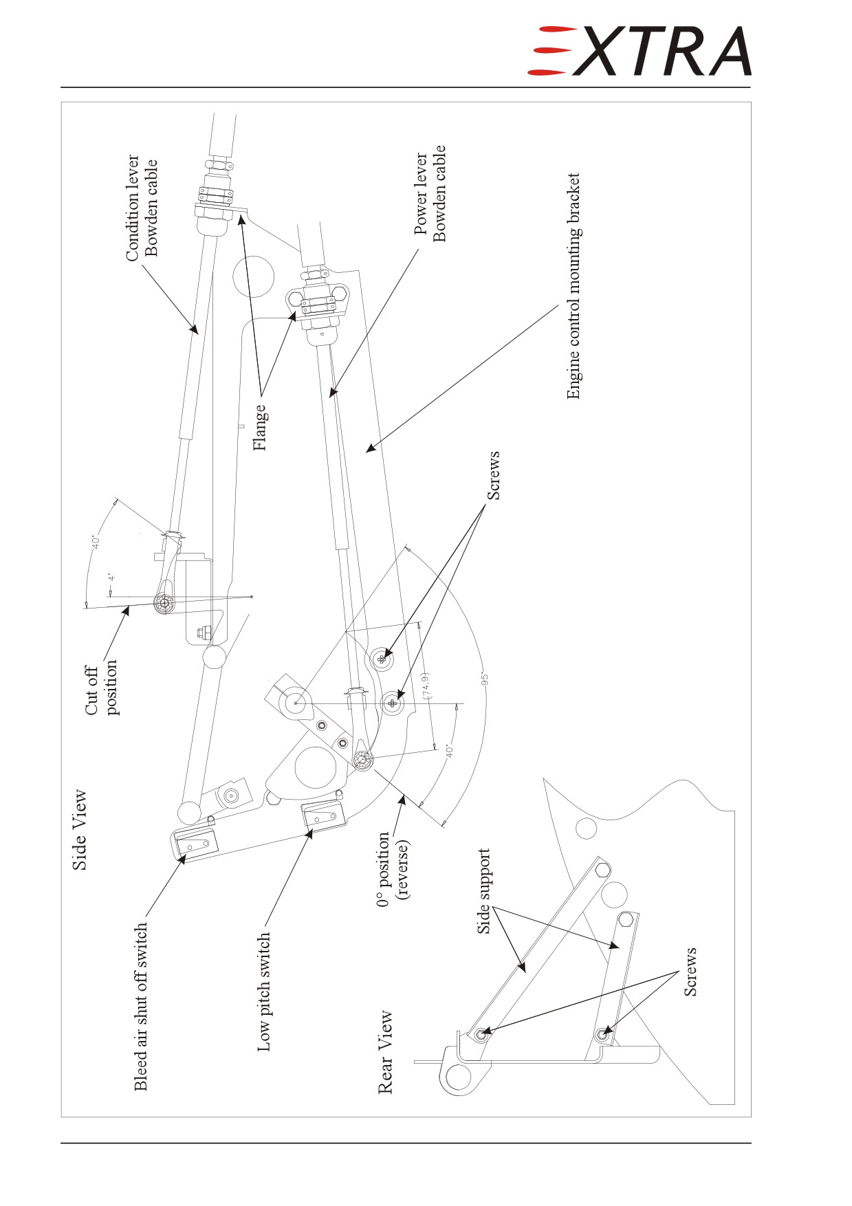
Figure 76-2
Engine Control Mounting Bracket
Page 6 76
76-10-02
Throttle Quadrant
Description
The throttle quadrant is installed in the cockpit middle console. It includes the
power and condition levers as well as the pitch trim wheel and indicator.
Removal
Detail Steps/Work Items
Key Items
1
Remove the trim wheel.
2
Remove the power lever handle.
3
Remove the condition lever handle.
4
Remove the upper part of the middle
Refer to Chapter 25-10-26
console paneling.
5
Remove the both Bowden cable rod-ends
and flanges from the quadrant
6
Remove static pressure hoses and cabin
pressure sensors from support rod.
7
Remove 4 screws on top of the quadrant
cover.
Do not bend or dent the trim tubing. Bending or denting it will increase
CAUTION
pitch trim friction to an unacceptable level.
8
Detach the trim controller.
9
Remove support tube.
10
Remove quadrant.
76 Page 7
Installation
Detail Steps/Work Items
Key Items
1
Reverse sequence of removal.
PR 1750 accelerator contains harmful vapors and is readily absorbed
WARNING
through the skin.
Avoid all contact with the skin and ingestion.
Always wash hands before eating or smoking.
Use adequate ventilation, hand protection and chemical-type goggles
when working with this product.
If accelerator contacts skin, flush area with warm water. Obtain medical
attention in cases of extreme exposure or ingestion.
PR 1750 sealant contains solvents.
WARNING
Use adequate ventilation or air-supplied respirators during application.
Avoid repeated or prolonged breathing of vapors.
In case of extreme vapor exposure, remove affected personnel to fresh
air immediately and obtain medical attention.
For complete health and safety information, a material safety data sheet
is available from the manufacturer.
2
If the lower bolts of the support tube have
been loosened or removed seal it with
PR1750.
3
Perform an engine control rigging check.
Refer to Subject 76-00-00
4
Check the function of the back-up
microphone.
76-10-03
Power Lever Bowden Cable
Description
The Power lever Bowden cable connects the power lever in the cabin with the
input power lever of the engine coordinator.
Removal
Detail Steps/Work Items
Key Items
1
Remove LH upper cowling.
Refer to Chapter 71-10-01
2
Remove upper part of the middle console
Refer to Chapter 25-10-26
paneling.
3
Remove the power Bowden cable (LH) rod-
ends and flanges from the quadrant.
Page 8 76
Detail Steps/Work Items
Key Items
4
Remove the Bowden cable rod-ends and
flanges from the input power lever of the
engine coordinator and engine control
mounting bracket.
5
With a firm pull, remove the Bowden cable
from the firewall.
Installation
Detail Steps/Work Items
Key Items
1
Reverse sequence of removal.
Refer to Product Label and Material Safety Data Sheet for health and
WARNING
safety information before using PR812.
2
Seal the Bowden cable firewall
breakthrough with PR812 from the engine
compartment side.
PR 1750 accelerator contains harmful vapors and is readily absorbed
WARNING
through the skin.
Avoid all contact with the skin and ingestion.
Always wash hands before eating or smoking.
Use adequate ventilation, hand protection and chemical-type goggles
when working with this product.
If accelerator contacts skin, flush area with warm water. Obtain medical
attention in cases of extreme exposure or ingestion.
PR 1750 sealant contains solvents.
WARNING
Use adequate ventilation or air-supplied respirators during application.
Avoid repeated or prolonged breathing of vapors.
In case of extreme vapor exposure, remove affected personnel to fresh
air immediately and obtain medical attention.
For complete health and safety information, a material safety data sheet
is available from the manufacturer.
3
Seal the Bowden cable firewall
breakthrough with PR1750 from the cabin
side.
4
Perform an engine control rigging check.
Refer to Subject 76-00-00
5
Check the function of the back-up
microphone.
76 Page 9
76-10-04
Condition Lever Bowden Cable
Description
The condition lever Bowden cable connects the condition lever in the cabin
with the condition lever of the engine coordinator.
Removal
Detail Steps/Work Items
Key Items
1
Remove LH upper cowling.
Refer to Chapter 71-10-01
2
Remove upper part of the middle console
Refer to Chapter 25-10-26
paneling.
3
Remove the condition Bowden cable (RH)
rod-ends and flanges from the quadrant.
4
Remove the Bowden cable rod-ends and
flanges from the condition lever of the
engine coordinator and engine control
mounting bracket.
5
With a firm pull, remove the Bowden cable
from the firewall.
Installation
Detail Steps/Work Items
Key Items
1
Reverse sequence of removal.
Refer to Product Label and Material Safety Data Sheet for health and
WARNING
safety information before using PR812.
2
Seal the Bowden cable firewall
breakthrough with PR812 from the engine
compartment side.
PR 1750 accelerator contains harmful vapors and is readily absorbed
WARNING
through the skin.
Avoid all contact with the skin and ingestion.
Always wash hands before eating or smoking.
Use adequate ventilation, hand protection and chemical-type goggles
when working with this product.
If accelerator contacts skin, flush area with warm water. Obtain medical
attention in cases of extreme exposure or ingestion.
Page 10 76
Detail Steps/Work Items
Key Items
PR 1750 sealant contains solvents.
WARNING
Use adequate ventilation or air-supplied respirators during application.
Avoid repeated or prolonged breathing of vapors.
In case of extreme vapor exposure, remove affected personnel to fresh
air immediately and obtain medical attention.
For complete health and safety information, refer to Le Joint Francais
material safety data sheet PR 1750 (LOAP 41).
3
Seal the Bowden cable firewall
For mixing and application of
breakthrough with PR1750 from the cabin
PR 1750 sealant refer to
side.
manufacturer's instructions.
4
Perform an engine control rigging check.
Refer to Subject 76-00-00
5
Check the function of the back-up
microphone.
76 Page 11
Chapter 77
Engine Indicating
77 Page 1
Table of Contents
77-00-00
GENERAL
3
Description.......................................................................................................... 3
Engine Indication Check
4
Normal Ground Idle Engine Indication
.............................................................. 4
77-00-01
Gas Generator Turbine Tachometer (N1)...................................................... 4
Removal
.............................................................................................................. 4
Installation
.......................................................................................................... 5
77-10-00
POWER
............................................................................................................. 6
77-10-01
Torque Transducer........................................................................................... 6
Figure 77-1
Engine Indication Transducers and Switches
6
Removal
.............................................................................................................. 6
Installation
.......................................................................................................... 7
77-10-02
Torque Switch
................................................................................................... 7
Removal/Installation
........................................................................................... 7
77-10-03
Propeller/Power Turbine RPM Sensor (N2)
.................................................. 7
Removal
.............................................................................................................. 7
Installation
.......................................................................................................... 8
77-20-00
TEMPERATURE
............................................................................................. 9
77-20-01
Thermocouple Wiring
...................................................................................... 9
77-20-02
Thermocouple Terminal Block........................................................................ 9
77-40-00
INTEGRATED ENGINE INSTRUMENT SYSTEMS
............................... 10
77-40-01
Analog Engine Indicator Cluster
.................................................................. 10
Removal/Installation
......................................................................................... 10
77-40-02
Digital Engine Indicator Cluster
................................................................... 10
Removal/Installation
......................................................................................... 10
Page 2 77
77-00-00
GENERAL
For specific repair and replacement information refer to Rolls-Royce 250-B17F
Series Engine Operation and Maintenance Manual (LOAP 1).
Description
The indication of engine parameters is presented on two integrated engine
instruments in the LH instrument panel. The upper unit is an analog-digital unit
which displays:
•
TRQ in percent
•
TOT in degree Celcius
•
N1 (compressor) in percent
•
N2 (propeller) in RPM
•
Oil pressure in psig
•
Oil temperature in degree Celcius
Although these parameters are displayed in one unit, they all have their
separate modules and are independent of each other. The same is valid for the
lower display unit which displays digital values only:
•
Bus voltage
•
Generator current in ampere
•
Battery current in ampere
•
Indicated outside air temperature in degree Celcius
•
Fuel temperature in degree Celcius
•
Fuel pressure in psig
77 Page 3
Engine Indication Check
The engine indication check consists of a engine run test in which the
plausibility of the indications are checked apart from obvious things like oil
system leakage if the oil pressure sensor has been exchanged.
Detail Steps/Work Items
Key Items
1
Before the engine run, check that all
pressure and RPM indications are zero and
temperature indications in line with the
OAT.
2
Start the engine.
Follow EXTRA 500 Pilot’s
Operating Handbook
procedures.
3
Set in ground idle.
4
Check engine indication is around the values
Refer to Normal Ground Idle
given in the following table.
Engine Indication table
Normal Ground Idle Engine Indication
TRQ
~10%
TOT
~540°C
N1
~65%
N2
~1750 RPM
OP
~90 psig
OT
In green area
FP
>10 psig
77-00-01
Gas Generator Turbine Tachometer (N1)
The gas generator turbine tachometer is installed on the LH forward engine
gearbox.
Removal
Detail Steps/Work Items
Key Items
1
Ensure BATT switch is OFF and no external
power connected.
2
Remove LH upper cowling.
Refer to Chapter 71-10-01
3
Disconnect electrical connector.
Page 4 77
Detail Steps/Work Items
Key Items
4
Remove tachometer
Installation
Detail Steps/Work Items
Key Items
1
Reverse sequence of removal.
Apply some engine oil to the
drive-spline before installing.
2
Perform engine indication check.
Refer to Subject 77-00-00
77 Page 5
77-10-00
POWER
77-10-01
Torque Transducer
The torque transducer is located in the engine compartment, on the LH side of
the battery, the aft sensor.
Side View
fwd
Transducers
Battery attachment frame
Switches
Sensing lines
To accumulator
Firewall
Figure 77-1
Engine Indication Transducers and Switches
Removal
Detail Steps/Work Items
Key Items
1
Ensure BATT switch is OFF and no external
power connected.
2
Remove LH upper cowling.
Refer to Chapter 71-10-01
3
Disconnect electrical connector.
Page 6 77
Detail Steps/Work Items
Key Items
4
Remove lock-wire.
5
Remove torque transducer
Installation
Detail Steps/Work Items
Key Items
1
Reverse sequence of removal.
Replace o-ring when
necessary.
2
Perform engine indication check.
Refer to Subject 77-00-00
77-10-02
Torque Switch
The torque switch is located in the engine compartment, on the LH side of the
battery, the aft sideward sensor (refer to Figure 79-1).
Removal/Installation
Detail Steps/Work Items
Key Items
1
Remove LH upper cowling.
Refer to Chapter 71-10-01
2
Disconnect electrical connector.
Never force the body of the sensor to turn against friction. It may change the
CAUTION
set-point. Always use a wrench on the spanner flats of the attachment fitting
for removal and installation.
3
Remove torque switch.
4
Reverse sequence of removal.
Apply Loctite 577 to torque
switch thread
77-10-03
Propeller/Power Turbine RPM Sensor (N2)
The propeller tachometer is installed on the RH forward engine gearbox.
Removal
Detail Steps/Work Items
Key Items
1
Ensure BATT switch is OFF and no external
power connected.
2
Remove upper cowlings.
Refer to Ch. 71-10-01/02
3
Disconnect electrical connector.
77 Page 7
Detail Steps/Work Items
Key Items
4
Remove tachometer.
Installation
Detail Steps/Work Items
Key Items
1
Reverse sequence of removal.
Apply some engine oil to the
drive-spline before installing.
2
Perform engine indication check.
Refer to Subject 77-00-00
Page 8 77
77-20-00
TEMPERATURE
Engine temperature is measured using K-type thermocouples and indicated as
TOT to the pilot.
77-20-01
Thermocouple Wiring
The thermocouple wiring from the terminal block (77-20-02) to the indicator is
Chromel - Alumel for the entire length, including connector pins. If any of this
wiring is to be replaced, wiring of the same material shall be used. Perform
engine indication check as per Subject 77-00-00.
77-20-02
Thermocouple Terminal Block
Engine thermocouple wiring and aircraft thermocouple wiring is connected at
the thermocouple terminal block. It is installed in the engine compartment on
the RH engine fire-shield.
It is crucial that the Chromel and Alumel wires from the engine are correctly
connected to those of the aircraft. Observe the following table:
Material
Aircraft wiring
Engine wiring
Chromel
Pos (+)
Yellow
White
Small diameter stud
Alumel
Neg (-)
Red
Green
Large diameter stud
77 Page 9
77-40-00
INTEGRATED ENGINE INSTRUMENT SYSTEMS
77-40-01
Analog Engine Indicator Cluster
The analog engine indicator cluster is installed in the LH instrument panel.
Removal/Installation
Detail Steps/Work Items
Key Items
1
Ensure BATT switch is OFF and no external
power connected.
2
Remove the RH and LH IFD.
Refer to Chapter 31-60-01
3
Disconnect both electrical connectors
4
Remove indicator cluster.
5
Install in reverse sequence of removal.
6
Perform engine indication check.
Refer to Subject 77-00-00
77-40-02
Digital Engine Indicator Cluster
The digital engine indicator cluster is installed in the LH instrument panel just
below the analog engine indicator cluster.
Removal/Installation
Detail Steps/Work Items
Key Items
1
Ensure BATT switch is OFF and no external
power connected.
2
Remove the RH and LH IFD.
Refer to Chapter 31-60-01
3
Disconnect electrical connector.
4
Remove 4 bolts
Use a ratchet with adequate
prolongation for holding nuts
in place.
5
Remove indicator.
6
Install in reverse sequence of removal.
7
Perform engine indication check.
Refer to Subject 77-00-00
Page 10 77
Chapter 78
Exhaust
78 Page 1
Table of Contents
78-00-00
GENERAL
3
Description
3
78-00-01
LH Exhaust Stack
3
Removal/Installation
3
78-00-02
RH Exhaust Stack
3
Removal/Installation
3
Page 2 78
78-00-00
GENERAL
Description
The exhaust system of the EXTRA 500 consists of two exhaust stacks, which
flanged to the engine with a V-band clamp.
Repair of the exhaust stacks is allowed only at EXTRA.
78-00-01
LH Exhaust Stack
Removal/Installation
Detail Steps/Work Items
Key Items
1
Remove the LH and RH upper cowlings.
Refer to Chapter 71-10-01/02
2
Remove the lower cowling.
Refer to Chapter 71-10-03
3
Remove engine anti-ice Bowden cable
Refer to Chapter 30-20-01/02
(from exhaust stack only) and micro switch.
4
Remove the V-band clamp.
5
Remove engine gear box vent line from
exhaust stack.
6
Unscrew the LH exhaust stack from the
helical metal hose.
7
Install in reverse sequence of removal.
Observe the following hint.
IMPORTANT
Make sure while setting the length of the helical metallic hose that the
forces on the engine flange while attaching the exhaust stack must be
minimal. Screw in the helical metallic hose minimum one full turn on
each side. Maximum two full turns each side are possible.
78-00-02
RH Exhaust Stack
Removal/Installation
Detail Steps/Work Items
Key Items
1
Remove the LH and RH upper cowlings.
Refer to Chapter 71-10-01/02
2
Remove the lower cowling.
Refer to Chapter 71-10-03
3
Remove the V-band clamp.
4
Unscrew the RH exhaust stack from the
helical metal hose.
Page Date:
78 Page 3
Detail Steps/Work Items
Key Items
5
Install in reverse sequence of removal.
Observe the following hint.
IMPORTANT
Make sure while setting the length of the helical metallic hose that the
forces on the engine flange while attaching the exhaust stack must be
minimal. Screw in the helical metallic hose minimum one full turn on
each side. Maximum two full turns each side are possible.
Page 4 78
Chapter 79
Oil
79 Page 1
Table of Contents
79-00-00
GENERAL
3
Description
3
Troubleshooting
3
Oil System Draining
3
79-10-00
STORAGE
4
Description
4
79-10-01
Engine Oil Supply Tank
4
Draining
4
Removal/Installation
4
79-10-02
Overpressure Valve
5
Removal
5
Installation
5
79-20-00
DISTRIBUTION
6
79-20-01
External Scavenge Oil Filter
6
Filter Element Replacement
6
Removal/Installation
6
79-20-02
Engine Oil Cooler
7
Draining
7
Removal/Installation
7
79-20-03
Oil Thermostat
7
Removal/Installation
8
79-20-04
Oil Lines
8
Draining
8
79-20-05
Fire Protection Box
8
Removal/Installation
8
79-30-00
INDICATION
10
79-30-01
Oil Pressure Transducer
10
Removal
10
Installation
11
79-30-02
Oil Temperature Sensor
11
Removal
11
Installation
11
79-30-03
Oil Pressure Switch
11
Removal
11
Installation
12
Page 2 79
Page Date