Extra 500. Maintenance Manual (2012) - page 18
79-00-00
GENERAL
For specific repair and replacement information refer to Rolls-Royce 250-B17F
Series Engine Operation and Maintenance Manual (LOAP 1).
Description
The EXTRA 500 oil system includes the following external components that
do not belong to the engine.
• Engine oil supply tank
• Oil vent system
• External scavenge oil filter
• Engine oil cooler
Troubleshooting
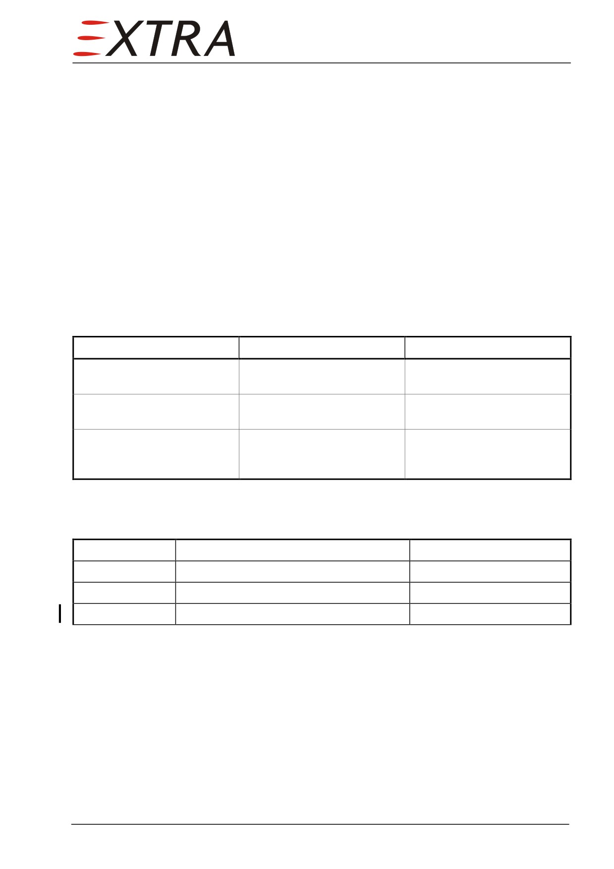
Complaint
Possible Cause
Remedy
Oil pressure at high altitude
Oil tank not pressurized
Check oil vent system,
too low
Refer to Subject 79-10-00
Excessive oil consumption
3 psi overpressure vent valve
Replace valve,
open
Refer to Subject 79-10-02
External oil filter pin popped
External oil filter element
Exchange external oil filter
clogged
element,
Refer to Subject 79-20-01
Oil System Draining
The complete oil system can be drained using the following procedure.
Detail Steps/Work Items
Key Items
1
Drain engine oil supply tank.
Refer to Subject 79-10-01
2
Drain engine oil cooler.
Refer to Subject 79-20-02
3
Replace external scavenge oil filter element.
Refer to Subject 79-20-01
Page Date:9. August 2013
79 Page 3
79-10-00
STORAGE
Description
The engine oil supply tank is located in the engine compartment, mounted on
the RH engine mount.
The oil supply tank is vented to the engine gearbox over a 2 psid overpressure
valve. In case this valve fails to open, the tank is vented overboard through a
3 psid overpressure valve. The reason for the oil tank pressurization is to
prevent too low oil pressure in high altitude.
Both overpressure valves are installed in the engine compartment on the RH
side of the engine mount ring. They are directly connected to the vent line T-
fitting.
79-10-01
Engine Oil Supply Tank
Draining
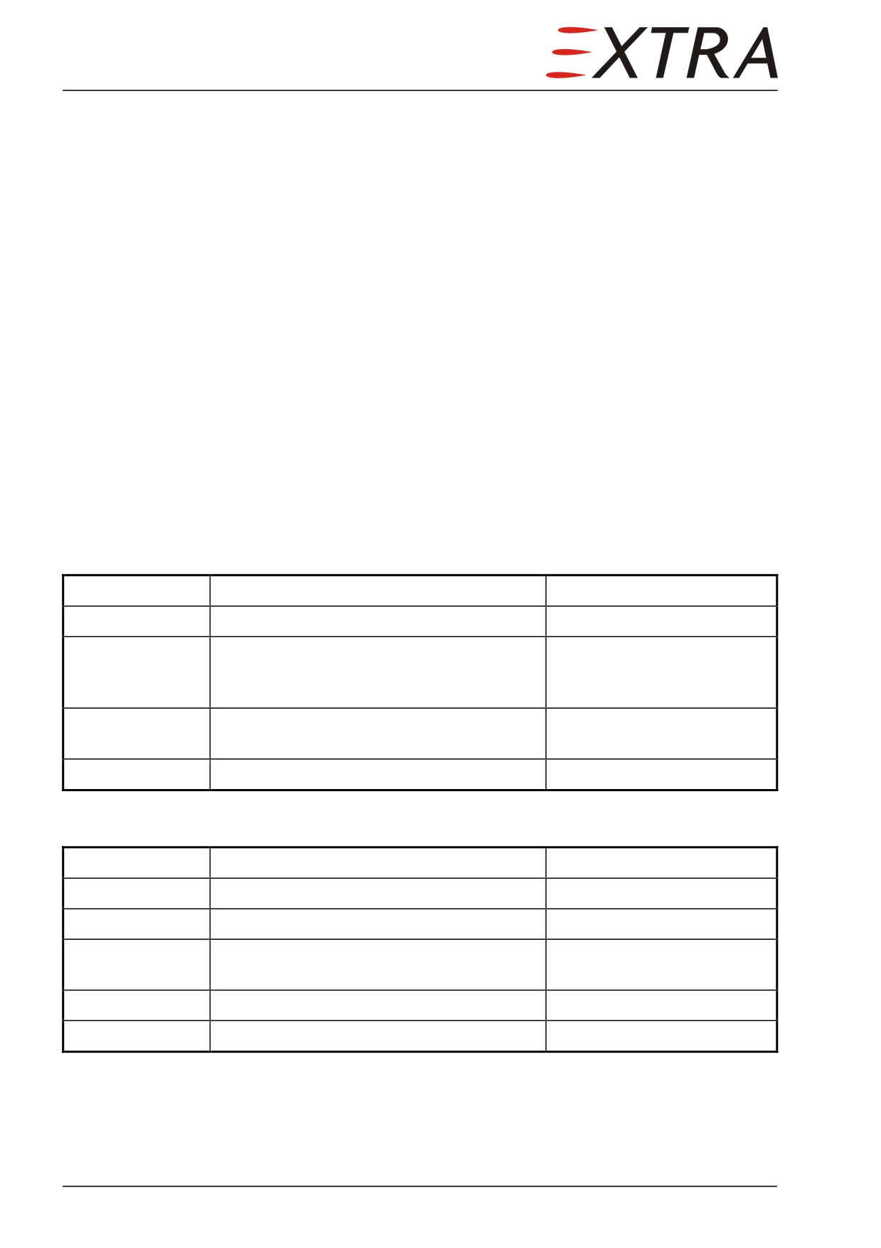
Detail Steps/Work Items
Key Items
1
Remove upper cowlings.
Refer to Chapter 71-10-01/02
2
Place an ‘oil slide’ under the lower engine
oil supply tank fitting to an appropriate
canister.
3
Disconnect the engine oil supply tank outlet
fitting and drain the oil from the tank.
4
Drain hose if applicable.
Refer to Subject 79-20-04
Removal/Installation
Detail Steps/Work Items
Key Items
1
Drain oil supply tank.
Refer to Draining Paragraph
2
Disconnect upper hoses. Plug hose fittings.
2 hoses
3
Remove oil supply tank.
2 worm drive hose clamps
and 1 bolt
4
Install in reverse sequence of removal.
5
Re-fill tank with oil to the appropriate level.
Refer to Chapter 12-10-04
Page 4 79
79-10-02
Overpressure Valve
Removal
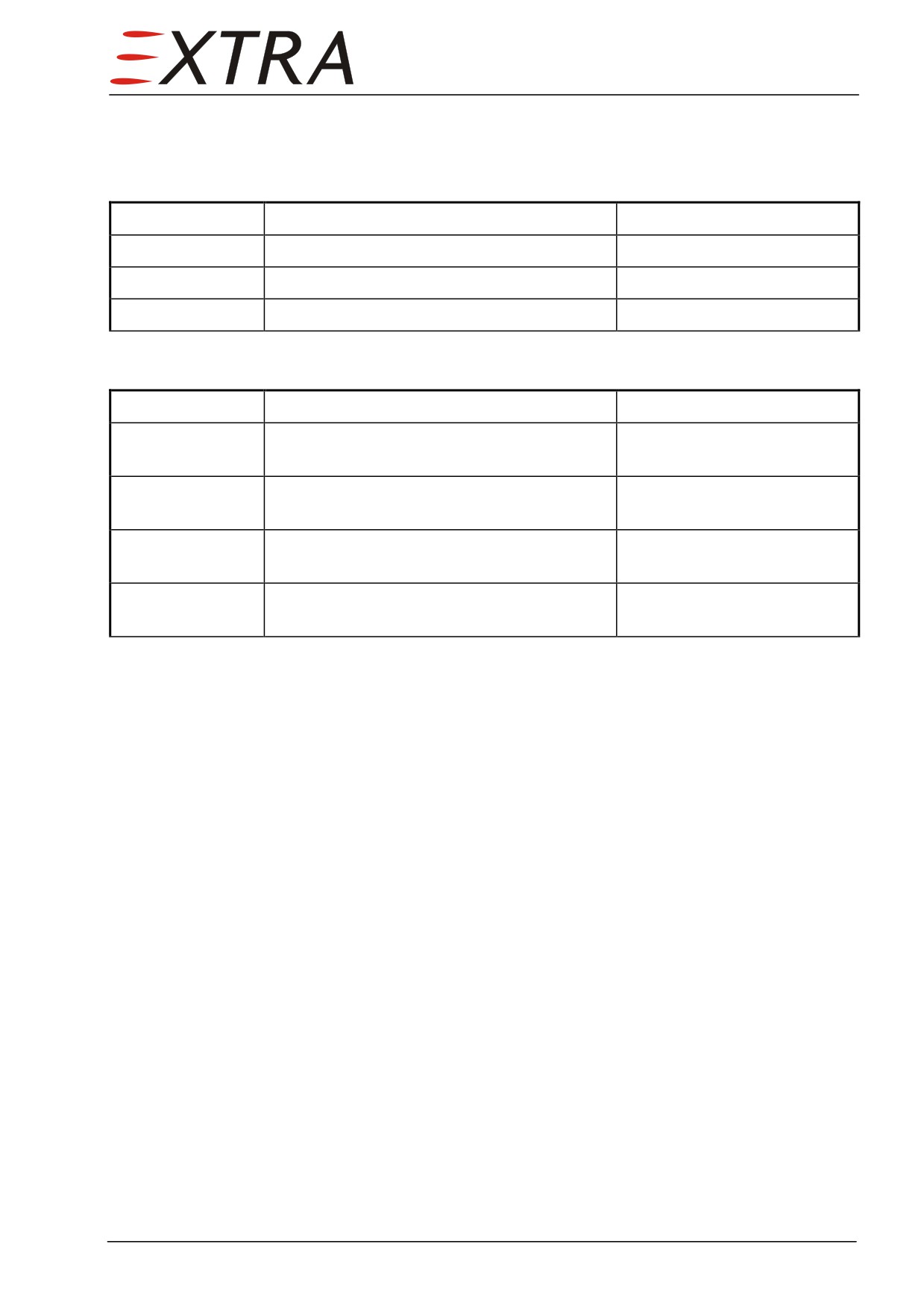
Detail Steps/Work Items
Key Items
1
Remove upper cowlings.
Refer to Chapter 71-10-01/02
2
Disconnect hose from overpressure valve.
3
Unscrew valve from T-fitting.
Installation
Detail Steps/Work Items
Key Items
1
Reverse sequence of removal.
Replace O-ring when
necessary.
2
Check the 2 psi valve is connected to the
hose routed to the engine gearbox.
3
Check the 3 psi valve is connected to the
hose routed overboard.
4
Check the arrows on both valves point away
from the T-fitting.
79 Page 5
79-20-00
DISTRIBUTION
79-20-01
External Scavenge Oil Filter
The external oil filter is located in the engine compartment, on the lower mount
pad of the engine. It is housed in a fire protection box and accessible after
removal of its cover. Refer to Figure 79-1.
Filter Element Replacement
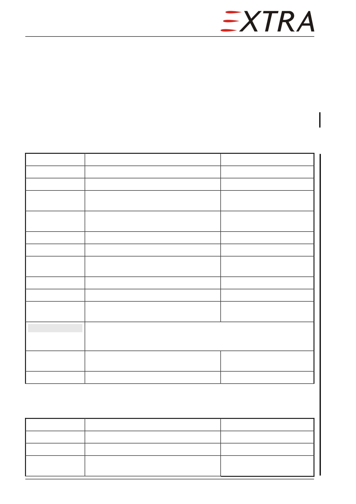
Detail Steps/Work Items
Key Items
1
Remove upper cowlings.
Refer to Chapter 71-10-01/02
2
Remove lower cowling.
Refer to Chapter 71-10-03
3
Remove fire protection box cover.
23 Phillips screws (2, Figure
79-1)
4
Place a suitable container under the oil filter
element.
5
Remove lock-wire and unscrew filter bowl.
6
Remove dirty element.
7
Remove O-ring and Back-up ring from filter
head.
8
Install new seal kit.
Purolator P/N 1741125
9
Install new element.
Purolator P/N 038088-08
10
Hand tighten filter bowl until tight against
head and lockwire.
NOTE
Only Purolator approved replacement parts may be used to maintain
warranty. Differential pressure bypass indicators and bowls are
matched assemblies and are not field replaceable.
11
Install fire protection box cover.
23 Phillips screws and clip
nuts (2 + 3, Figure 79-1)
12
Install cowlings
Refer to Chapter 71
Removal/Installation
Refer to Figure 79-1.
Detail Steps/Work Items
Key Items
1
Remove upper cowlings.
Refer to Chapter 71-10-01/02
2
Remove lower cowling.
Refer to Chapter 71-10-03
3
Remove fire protection box cover.
23 Phillips screws and clip
nuts (2 + 3, Figure 79-1)
Page 6 79
Page Date:
Detail Steps/Work Items
Key Items
4
Disconnect oil lines from external oil filter.
Use a funnel to collect oil
Plug ends.
from lines in a suitable
container.
5
Remove oil filter.
2 bolts (9, Figure 79-1)
6
Install in reverse sequence of removal.
7
Refill tank with oil to the appropriate level.
79-20-02
Engine Oil Cooler
The oil cooler is installed in the engine compartment on the RH side
Draining
Detail Steps/Work Items
Key Items
1
Remove upper cowlings.
Refer to Chapter 71-10-01/02
2
Remove lower cowling.
Refer to Chapter 71-10-03
3
Place an “oil slide” under the lower engine
oil cooler fitting to an appropriate canister.
4
Disconnect the lower engine oil cooler
fitting and drain the oil from the oil cooler.
5
Drain hose if applicable.
Refer to Subject 79-20-04
Removal/Installation
Detail Steps/Work Items
Key Items
1
Drain engine oil cooler.
Refer to Draining Paragraph
2
Disconnect upper hose.
3
Remove forward air duct.
4
Remove cooler from aft airduct.
The aft airduct can be
removed from the structure to
gain better access to the aft
airduct to cooler mounting
bolts.
5
Install in reverse sequence of removal.
79-20-03
Oil Thermostat
The oil thermostat is mounted in the oil cooler housing at outlet to oil tank.
Page Date:9. August 2013
79 Page 7
Removal/Installation
Detail Steps/Work Items
Key Items
1
Remove upper cowlings.
Refer to Chapter 71-10-01/02
2
Remove oil cooler.
From serial N 1003
Refer to Subject 79-20-02
3
Remove lock-wire.
4
Unscrew oil thermostat.
5
Install in reverse sequence of removal.
79-20-04
Oil Lines
Draining
Detail Steps/Work Items
Key Items
1
Remove upper cowlings.
Refer to Chapter 71-10-01/02
2
Remove lower cowling.
Refer to Chapter 71-10-03
3
Place suitable “oil slides” and/or canisters
under the lower oil line fittings.
4
Disconnect hoses or tubes on lower fittings
Hold open hose end
and drain.
downward where necessary.
79-20-05
Fire Protection Box
A fire protection box is installed to house the external oil filter. Refer to Figure
79-1.
Removal/Installation
Detail Steps/Work Items
Key Items
1
Remove external oil filter.
Refer to Subject 79-00-01
2
Disconnect air hose from fire protection box
(4).
3
Remove carrier (7) and fire protection box
3 bolts (8)
(4).
4
Remove bracket (6) if applicable.
3 bolts (5)
5
Install in reverse sequence of removal.
Page 8 79
Page Date:
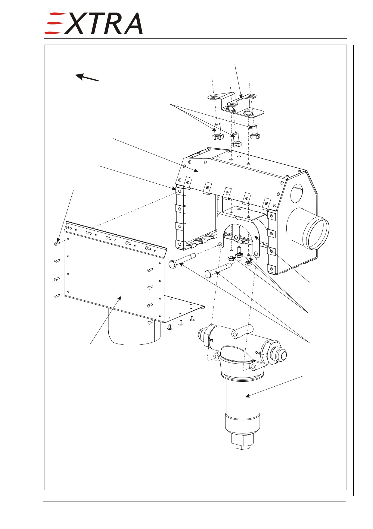
6
fwd
5
4
3
2
7
8
9
1
10
Legend:
1
cover
2
Phillips screw (x23)
3
clip nut (x23)
4
fire protection box
5
bolt
6
bracket
7
carrier
8
bolt
9
bolt
10 oil filter
Figure 79-1
Fire Protection Oil Filter
Page Date:
79 Page 9
79-30-00
INDICATION
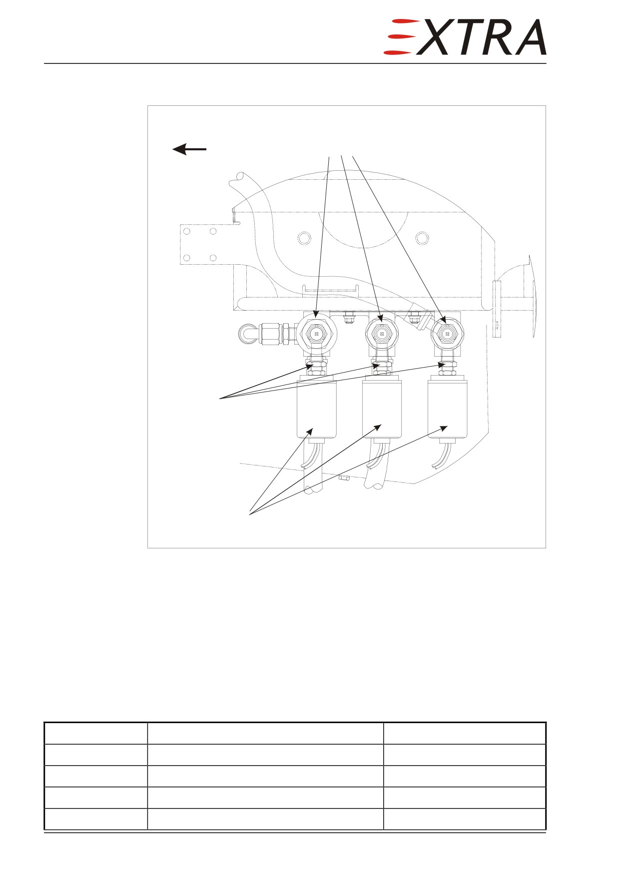
Top View
fwd
Transducers
Spanner flats
FUEL
OIL
TRQ
Switches
Figure 79-2
Engine Indication Transducers and Switches
79-30-01
Oil Pressure Transducer
The oil pressure transducer is located in the engine compartment, on the LH
side of the battery, the middle sensor on top (refer to Figure 77-1 and 79-1).
Removal
Detail Steps/Work Items
Key Items
1
Remove LH upper cowling.
Refer to Chapter 71-10-01
2
Disconnect electrical connector.
3
Remove lock-wire.
4
Remove oil pressure transducer.
Page 10 79
Page Date:
Installation
Detail Steps/Work Items
Key Items
1
Reverse sequence of removal.
Replace o-ring when
necessary.
2
Perform engine indication check.
Refer to Chapter 77-00-01
79-30-02
Oil Temperature Sensor
The oil temperature sensor is installed in the engine compartment on the LH
forward engine gearbox, at oil-in-connection fitting.
Removal
Detail Steps/Work Items
Key Items
1
Remove LH upper cowling.
Refer to Chapter 71-10-01
2
Disconnect electrical connector.
3
Remove lock-wire.
4
Remove oil temperature sensor from fitting.
Use a funnel to collect oil
from line in a suitable
container.
5
Plug oil temperature sensor fitting.
Installation
Detail Steps/Work Items
Key Items
1
Reverse sequence of removal.
Replace o-ring when
necessary.
2
Perform engine indication check
Refer to Chapter 77-00-01
79-30-03
Oil Pressure Switch
The oil pressure switch is located in the engine compartment, on the LH side of
the battery, the middle sideward sensor (refer to Figure 79-1).
Removal
Detail Steps/Work Items
Key Items
1
Remove LH upper cowling.
Refer to Chapter 71-10-01
2
Disconnect electrical connector.
Page Date:
79 Page 11
Detail Steps/Work Items
Key Items
Never force the body of the sensor to turn against friction. It may
CAUTION
change the set-point. Always use a wrench on the spanner flats of the
attachment fitting for removal and installation.
3
Remove oil pressure switch.
Installation
Detail Steps/Work Items
Key Items
1
Reverse sequence of removal.
Apply Loctite 577 to pressure
switch thread
2
Perform engine indication check
Refer to Chapter 77-00-01
Page 12 79
Page Date:
Chapter 80
Starting
80 Page 1
Table of Contents
80-00-00
GENERAL
3
Description
3
80-10-00
CRANKING
4
Motoring
4
Page 2 80
80-00-00
GENERAL
For specific repair and replacement information refer to Rolls-Royce 250-B17F
Series Engine Operation and Maintenance Manual (LOAP 1).
Description
The ENGINE START switch is located on the instrument panel and has three
positions:
• START
• IGN
• IGN OFF
Engine starting on the EXTRA 500 is semi-automatic. The start switch is
shortly set at START and automatically falls back in the IGN setting. This will
initiate the start cycle directed by the Generator Control Unit and performed by
the starter generator. The condition lever must be set during the cycle to add
fuel. See EXTRA 500 Pilot’s Operating Handbook for exact procedure. When
the engine has reached a certain RPM (N1), the starter will automatically
switch off. Ignition must be switched off manually to prevent excessive spark
plug wear.
80 Page 3
80-10-00
CRANKING
Cranking may be accomplished with the ENGINE MOTORING switch, located
next to the ENGINE START switch. The ENGINE MOTORING switch has three
positions:
• MOTORING
• ABORT
• NORMAL
NOTE
For a normal engine start, the ENGINE MOTORING switch MUST be in the
NORMAL position. Always return the switch in the NORMAL position.
The ABORT position is to abort a normal engine start. It will immediately
switch off the electrical starter and ignition. It does not cut the fuel.
Motoring
Do not motor the engine while aircraft jacked.
CAUTION
Motoring may be used for maintenance and to cool down the engine prior to
engine start to prevent a hot start. Normally, a TOT of below 100°C and a good
battery will produce a start within limits.
Detail Steps/Work Items
Key Items
1
Secure aircraft with wheel chocks.
2
Perform Before Starting Engine procedure.
Refer to EXTRA 500
Pilot’s Operating Handbook,
Section 4
3
Check condition lever in CUT OFF.
During motoring the propeller will turn and exhaust gasses will be hot.
WARNING
Make sure no one or nothing can be struck by a propeller blade or is in
the propeller/exhaust jet stream.
Motoring is the same as starting for the starter generator. Apply the
CAUTION
normal starter limits to motoring also: Three times 30 seconds max.
with a 60 second cool down period. After the third time, wait at least one
half hour.
4
Switch and hold MOTORING.
5
Check oil pressure indication.
6
Return the switch to ABORT.
7
After motoring switch to NORMAL.
Page 4 80
Chapter 91
Charts
91 Page 1
Table of Contents
EA-9B213.30A
Cabin Pressure Control, HP
up to serial N° 1002
EA-9B213.30B
Cabin Pressure Control, HP
from serial N° 1003
EA-9B215.10B
Air Condition, HB
EA-9B215.20A
Bleed Air System
up to serial N° 1002
EA-9B215.20B
Bleed Air System
from serial N° 1003
EA-9B235.17
MKR / Audio, RM
EA-9B243.10A
DC Generation I, PP
up to serial N° 1002
EA-9B243.10B
DC Generation I, PP
from serial N° 1003
EA-9B243.20A
DC Generation II, PR
up to serial N° 1002
EA-9B243.20B
DC Generation II, PR
from serial N° 1003
EA-9B243.40A
E-Box
EA-9B243.41A
PCB Board E-Box
EA-9B244.10A
External Power, PD
up to serial N° 1002
EA-9B244.10B
External Power, PD
from serial N° 1003
EA-9B244.20
Battery charge, PL
EA-9B246.10A
DC Distribution
EA-9B246.10B
DC Distribution
from serial N° 1003
EA-9B252.10A
12V Power receptacle (Cigar Lighter), MM
EA-9B252.11A
12V Sockets,TH
EA-9B256.11
ELT ARTEX ME 406, DA
EA-9B271.17B
AutoPilot-STEC-55X, CA
EA-9B271.18A
Yoke (Control stick) Left, Right
EA-9B273.30A
Stall Warning, WH
up to serial N° 1002
EA-9B273.30B
Stall Warning, WH
from serial N° 1003
EA-9B275.20A
Flap-System, CG
up to serial N° 1002
EA-9B275.20B
Flap-System, CG
from serial N° 1003
EA-9B276.10A
Prop Overspeed, ES
EA-9B284.10A
Fuel QTY Indication, QX
EA-9B284.13A
PCB-Board 1
EA-9B284.30
Low Fuel Warning, WW
up to serial N° 1002
EA-9B284.30A
Low Fuel Warning, WW
from serial N° 1003
EA-9B303.10A
Pitot-Static-Stall-Heat, HG
up to serial N° 1002
EA-9B303.10B
Pitot-Static-Stall-Heat, HG
from serial N° 1003
EA-9B304.10A
Anti ICE Intake, HM
up to serial N° 1002
EA-9B304.10B
Anti ICE Intake, HM
from serial N° 1003
EA-9B304.20A
Windshield Heat, HF
up to serial N° 1002
EA-9B304.20B
Windshield Heat, HF
from serial N° 1003
EA-9B310.10A
Boots, HH
up to serial N° 1002
EA-9B310.10B
Boots, HH
from serial N° 1003
EA-9B314.30B
Airspeed Warning, WV
EA-9B315.80B
Annunciator Panel, WW
up to serial N° 1002
EA-9B315.80C
Annunciator Panel, WW
from serial N° 1003
EA-9B315.81
PCB-Board Warning/Annunciator
up to serial N° 1002
EA-9B315.90B
Low Voltage Monitor, WL
up to serial N° 1002
EA-9B315.90C
Low Voltage Monitor, WL
from serial N° 1003
EA-9B316.40A
Digital Instrument Package, EY
EA-9B316.50A
Engine Instrument Package, EZ
EA-9B317.10A
Engine Warning, LW
up to serial N° 1002
EA-9B317.10B
Engine Warning, LW
from serial N° 1003
Page 2 91
Page Date:
11. July 2012
EA-9B323.10A-1
Landing Gear Control, GA
up to serial N° 1002
EA-9B323.10C
Landing Gear Control, GA
from serial N° 1003
EA-9B323.20A
Gear Warning, GA
up to serial N° 1002
EA-9B323.20B
Gear Warning, GA
from serial N° 1003
EA-9B334.10A
Strobe Light, LB
EA-9B334.20A
NAV Light, LC
EA-9B334.35A
Landing Light, LA
up to serial N° 1002
EA-9B334.35B
Landing Light, LA
from serial N° 1003
EA-9B334.40A
Cabin-Dome-MAP Light, LJ
EA-9B334.50A
Courtesy Light, LY
EA-9B334.55A
Ice Light, LN
EA-9B334.60A
Recognition Lights, LF
up to serial N° 1002
EA-9B334.60B
Recognition Lights, LF
from serial N° 1003
EA-9B334.75A
Glare Light
EA-9B334.81A
Luminiszenz-Backlighting
EA-9B334.90A
Dimming, LH
EA-9B334.91A
Dimming
EA-9B342.65
IFD LH, FG
up to serial N° 1002
EA-9B342.65A
IFD LH, FG
from serial N° 1003
EA-9B342.66
IFD RH, FG
up to serial N° 1002
EA-9B342.66A
IFD RH, FG
from serial N° 1003
EA-9B342.67
Keypad, FG
EA-9B342.73
Attitude Gyro, FM
EA-9B344.14
Weather Detec TWX-670, SS
EA-9B344.15
Traffic System TAS-610, SD
EA-9B344.16
Broadcast MLB-700, TL
EA-9B344.17
Datalink 2-way MLX-770, TS
EA-9B345.47
DME KDM 706A, SN
EA-9B345.58
ATC BXP6402-1R, SH
up to serial N° 1002
EA-9B345.58A
ATC BXP6402-1R, SH
from serial N° 1003
EA-9B360.11
Prop Heat, HI
EA-9B360.11A
Prop Heat, HI
from serial N° 1003
EA-9B411.70A_1
PCB Annunciator
from serial N° 1003
EA-9B411.70A_2
PCB Annunciator
from serial N° 1003
EA-9B527.10
Door Warning
up to serial N° 1002
EA-9B527.10A
Door Warning
from serial N° 1003
EA-9B731.10A
Fuel Pump / Filter, QB
up to serial N° 1002
EA-9B731.10B
Fuel Pump / Filter, QB
from serial N° 1003
EA-9B731.30A
Fuel Trans, QF
up to serial N° 1002
EA-9B731.30B
Fuel Trans, QF
from serial N° 1003
EA-9B731.40A
Fuel Flow, QY
EA-9B743.10A
Start / Ignition, JB
up to serial N° 1002
EA-9B743.10B
Start / Ignition, JB
from serial N° 1003
EA-9B752.15A
Panel Fan, HK
Page Date:
11. July 2012
91 Page 3