Extra 500. Maintenance Manual (2012) - page 16
Detail Steps/Work Items
Key Items
8
Apply Ottoseal S72 to the window in the
area of the frame as outlined on Figure 56-4.
9
Install frame.
10
Install the window attachment bolts and
tighten nuts to 3 thru 3.5 Nm (26 thru 31
in.lbs).
11
Complete Ottoseal S72 where necessary and
For curing time and
flatten with low surface tension water.
conditions refer to Ottoseal
S72 data sheet.
12
Apply 1 layer 92110 glass fiber to build new
Refer to Chapter 51
cover, if applicable.
13
Apply paint, if applicable.
Refer to Chapter 51
14
Install paneling,
Refer to Chapter 25 or 52
Page Date:9. August 2013
56 Page 13
Chapter 57
Wings
57 Page 1
TABLE OF CONTENTS
57-00-00
GENERAL
3
Description.......................................................................................................... 3
57-10-00
CENTER WING
............................................................................................... 4
Description.......................................................................................................... 4
Removal
.............................................................................................................. 4
Installation
.......................................................................................................... 6
Figure 57-1
Hoisting the Wing
............................................................................................... 6
Figure 57-2
Wing to Fuselage Attachment
............................................................................. 7
57-30-00
WING TIPS
....................................................................................................... 8
Description.......................................................................................................... 8
57-50-00
TRAILING EDGE AND TRAILING EDGE DEVICES.............................. 9
57-50-01
Flaps
................................................................................................................... 9
Description.......................................................................................................... 9
Removal/Installation
........................................................................................... 9
Figure 57-3
Inner Flap Structure
......................................................................................... 10
Figure 57-4
Outer Flap Structure
11
57-60-00
AILERONS
..................................................................................................... 12
Description........................................................................................................ 12
Removal/Installation
......................................................................................... 12
Figure 57-5
Aileron Structure
.............................................................................................. 13
Page 2 57
Page Date:
57-00-00
GENERAL
Description
The EXTRA 500 features a straight tapered all composite cantilever wing. The
one piece wing consists of a CFRP wing-box serving as structure for the
bending and torsional loads. The GFRP nose section equipped with the de-ice
boots
(=> ref. to Chapter 30) is part of the aerodynamic wing section and carries
shear due to aerodynamic lift forces into the wing box structure. To achieve
minimum drag natural laminar flow wing sections have been designed
specially for the EXTRA 500. Wing relative thickness is 16,5% at the root
section gradually changing into the 12% wing section used at the tip. Wing
twist distribution is selected to keep the wing sections within the low drag
bucket in cruise flight.
Wing-Structure
Spars: The wing uses 1 double cell front spar at 22.6% chord and 1 single
cell rear spar at 68.6% chord (carry-thru) to 60% chord (tip). Caps and webs
are made of CFRP with PMI foam core. The tiplets are not part of the primary
wing structure.
Skin: The wing skin is a composite sandwich structure with CFRP facing
layers and honeycomb core.
Ribs: In the torsion wing box 7 CFRP ribs are used each side: structural root
and fuel tank rib at Y±550, slosh rib with flapper valves at Y±800, slosh rib at
Y±1550, structural and fuel tank rib at Y±2550, fuel tank end rib (long range)
at Y±4300, structural rib at Y±4400 and the structural tip rip at Y±5500, which
extends to the nose section.
In addition 5 GFRP ribs are used in the D-nose section each side at Y± 550,
Y±1550, Y±2550, Y±3400, Y±3600, Y±4400.
Fuel tank:
The wing fuel tank is an integral part of the wingbox between
the main spars, the root rib at Y±550 and Y±4300.
Flaps:
=> refer to section 57-50
Ailerons:
=> refer to section 57-60
Nose section:
The nose skin is a composite sandwich structure with GFRP
facing layers and honeycomb core. It incorporates the pneumatic de-icing
boots.
57 Page 3
57-10-00
CENTER WING
Description
The wing fuselage attachment fittings are a conventional steel design. Two
fittings are bolted to a forward fuselage frame , another two fittings are bolted
to an aft fuselage frame providing four wing attachment lugs. These lugs match
four bushings, two in the main spar and two in the aft spar of the wing. The
connection is completed by four high strength corrosion resistant steel bolts
installed against flight direction. The lugs of the fuselage fittings feature a high
quality thermoplastic liner for bolt surface protection. The design satisfies fail
safe requirements, any single bolt may fail.
Removal
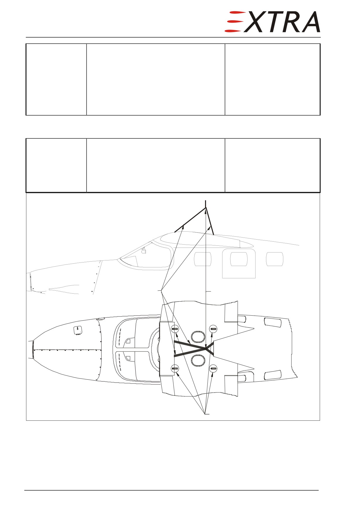
Refer to Figure 57-1 and Figure 57-2. Wing removal is done by hoisting the
wing, removing the fuselage beneath it and lowering the wing on suitable
supports. The weight of the (dry) wing including flaps and ailerons is less than
300kg. Be sure that your hoist assembly and lifting straps provide enough load
bearing capacity.
Special tools required for wing removal:
EA-15001.2w
(bolt extractor, drawing or tool itself available from EXTRA)
Detail Steps/Work Items
Key Items
1
Ensure BATT switch is OFF and no external
power connected.
2
Drain all fuel
3
Remove two avionic bay access panels, the
Refer to Chapter 51-00-01
wing center fairing. and the fuel sump
access panels.
4
Remove all screws attaching the fuselage
Don’t forget the two screws
skin to the wing.
underneath the flaps.
5
Disconnect all electric connectors in the
Required tools are available
avionic bay and center wing nose section.
at a standard avionic shop.
6
Disconnect the main bonding connection in
Hex nut on stud bolt
the left forward section of the avionic bay
7
Disconnect tubing for pitot static system and
de-ice boots, protect open lines against
FOD.
8
Disconnect aileron control cables.
Three turnbuckles in wing
nose section
refer to Chapter 27
9
Disconnect all fuel supply lines (one on
Refer to Chapter 28-20-06
each side).
Page 4 57
Page Date:
10
Disconnect fuel lines running from and to
Accessible after removal of
the jet pumps.
avionic bay access panels
11
Carefully separate the silicone sealing
between fuselage and wing with a sharp
knife.
12
Sling two industrial hoisting straps (at least
It is helpful to use specially
2” wide) around the wing center section.
bended welding wire or
similar to get the straps
through the gap between
wing and fuselage.
13
Install the hoisting assembly and relieve the
wing fuselage connection. Take care of the
attachment flange of the center panel when
loading the straps, use wooden blocks or
similar to protect the flange. Be sure to
attach the hoisting assembly above the
wings center of gravity to avoid a nose or
tail heavy condition when lifting it. The
wing weight is approx. 250 kg (551 lbs). Be
sure to provide a lifting force appropriate to
this weight to avoid damage to the remai-
ning attachment points by uncontrolled wing
movement. This is likely to occur when the
attachment bolts are fix, but the wing
connections are not fix in all directions any
more.
14
Remove safety plates at main spar bolts
(also removes electric bonding strips) and
safety wire at rear spar securing bolts.
Remove rear spar securing washers and
bolts (concentric bolt M10)
NOTE
Be sure to have at least one person on suitable supports at each wing tip
before extracting the second bolt to counteract any undesirable
movement of the wing.
NOTE
It is advisable to begin with both bolts on one side to get a feel for the
proper relief tension of the hoist assembly while the wing is able to
swivel around the remaining bolts.
15
Extract the attachment bolts with special
Extracting tool EA-15001.2w
tool.
required
(See Chapter 01-00-02)
16
Slowly lift the wing from the fuselage and
take care of the electric wiring.
57 Page 5
17
As soon as the wing is completely free
remove the fuselage underneath the wing
and lower the wing on suitable supports
with protective lining. (Foam, carpet or
similar). The wing should be supported
underneath structural ribs, preferably the
ribs in front of the gap between the inner
and outer flap.
Installation
Install in reverse order of removal
Install wing attachment bolts with grease.
Aeroshell Grease 22c
Observe special torque values for:
Refer to chapter 20-10-04
Securing bolt rear bolts (Bolt M10)
retaining sheets front bolts (two Bolts M5)
Side view
Wing hoisting straps
approximate location of CG for lifting wing
Top view
wing attachment bolts
Figure 57-1
Hoisting the Wing
Page 6 57
Page Date:
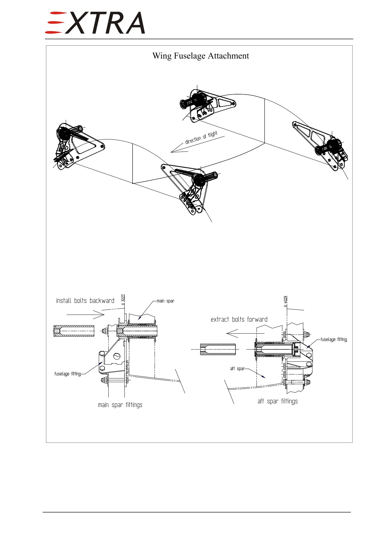
Figure 57-2
Wing to Fuselage Attachment
57 Page 7
57-30-00
WING TIPS
Description
The wing tips are non structural CFRP parts attached to a flange along the wing
tip rib. Removing the wing tips gives access to the outer compartment of the
wing between the main and aft spar. A transparent polycarbonate cover at the
leading edge of the wing tip aerodynamically integrates the Navigation Strobe-
Light Combination. The wing tips are lightning protected by an outer CFRP
layer incorporating a metallic mesh.
Page 8 57
Page Date:
57-50-00
TRAILING EDGE AND TRAILING EDGE DEVICES
57-50-01
Flaps
Description
Refer to Figure 57-3 and Figure 57-4.The flaps are of one spar dual torsion box
all-CFRP-composite construction. For structural reason each flap is divided in
two parts. The inboard part extends from Y ± 550 to Y ± 2550, the outboard
from Y ± 2550 to Y ± 4400.
For adjustment of flap actuation, guidance and position indicating refer to
Chapter 27.
Removal/Installation
Move flaps to 30° position (wing flap position switch at right main panel).
Perform the following steps for LH and RH side flaps each.
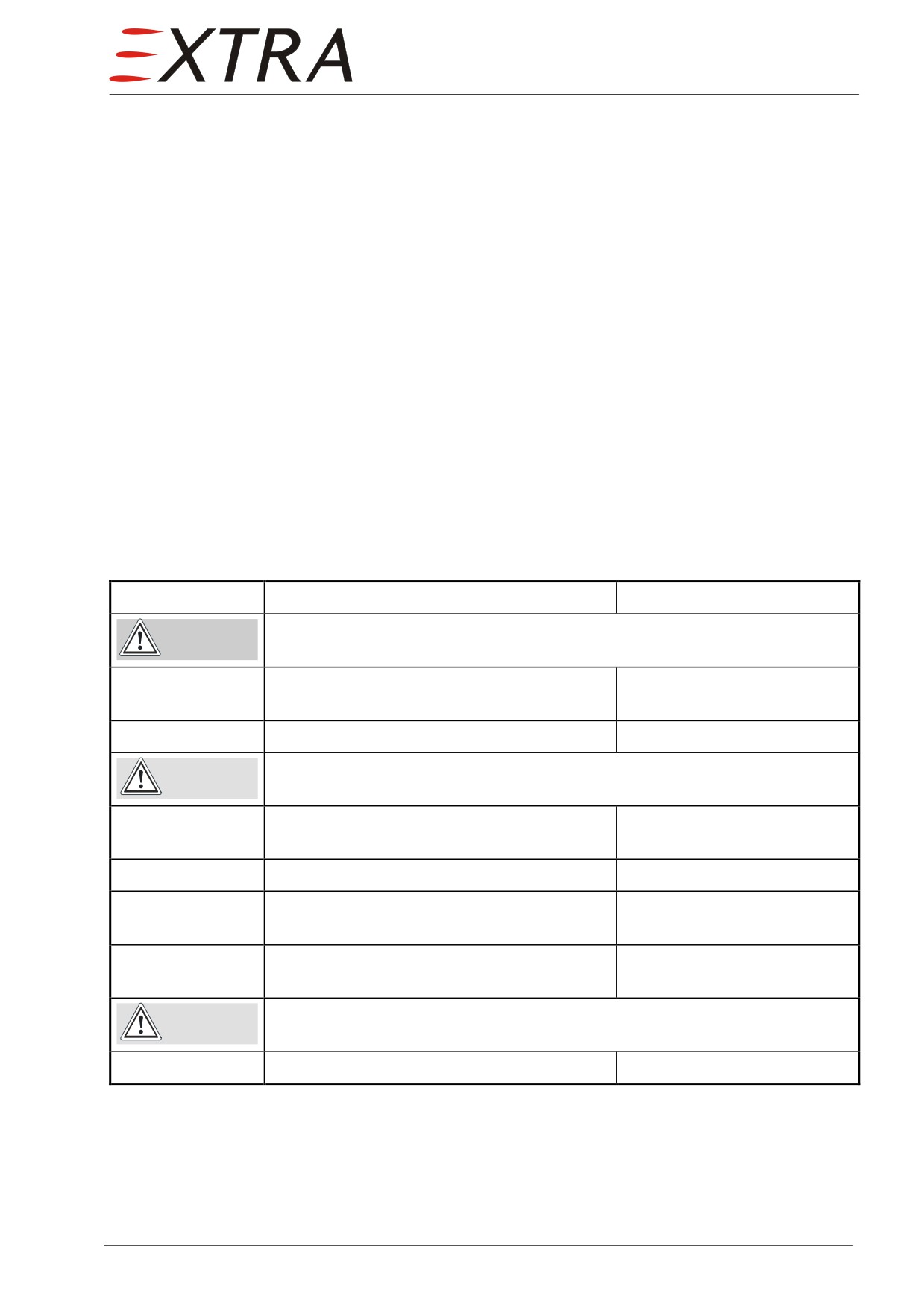
Detail Steps/Work Items
Key Items
Pull circuit breakers FLAP and FLAP CTRL at left side circuit breaker
WARNING
panel
1
Remove safety wire from ball at connection
rod to watchdog potentiometer
2
Disconnect ball from connecting rod
Take care not to move or loosen arm from shaft. Otherwise
CAUTION
readjustment will be required as per Ch. 27-50-00
3
Disconnect bolts connecting inner and outer
1 hex bolt each
transmission rod to flap bracket
4
Disconnect 2 hex bolts at middle flap track
5
Remove inner flap segment from inboard
It is recommended to get
guidance keyway
some assistance
6
Remove outer flap segment from outboard
It is recommended to get
guidance keyway
some assistance
Before re-installation, perform flap track adjustment as per
CAUTION
Ch. 27-50-00
Install in reverse sequence of removal
57 Page 9
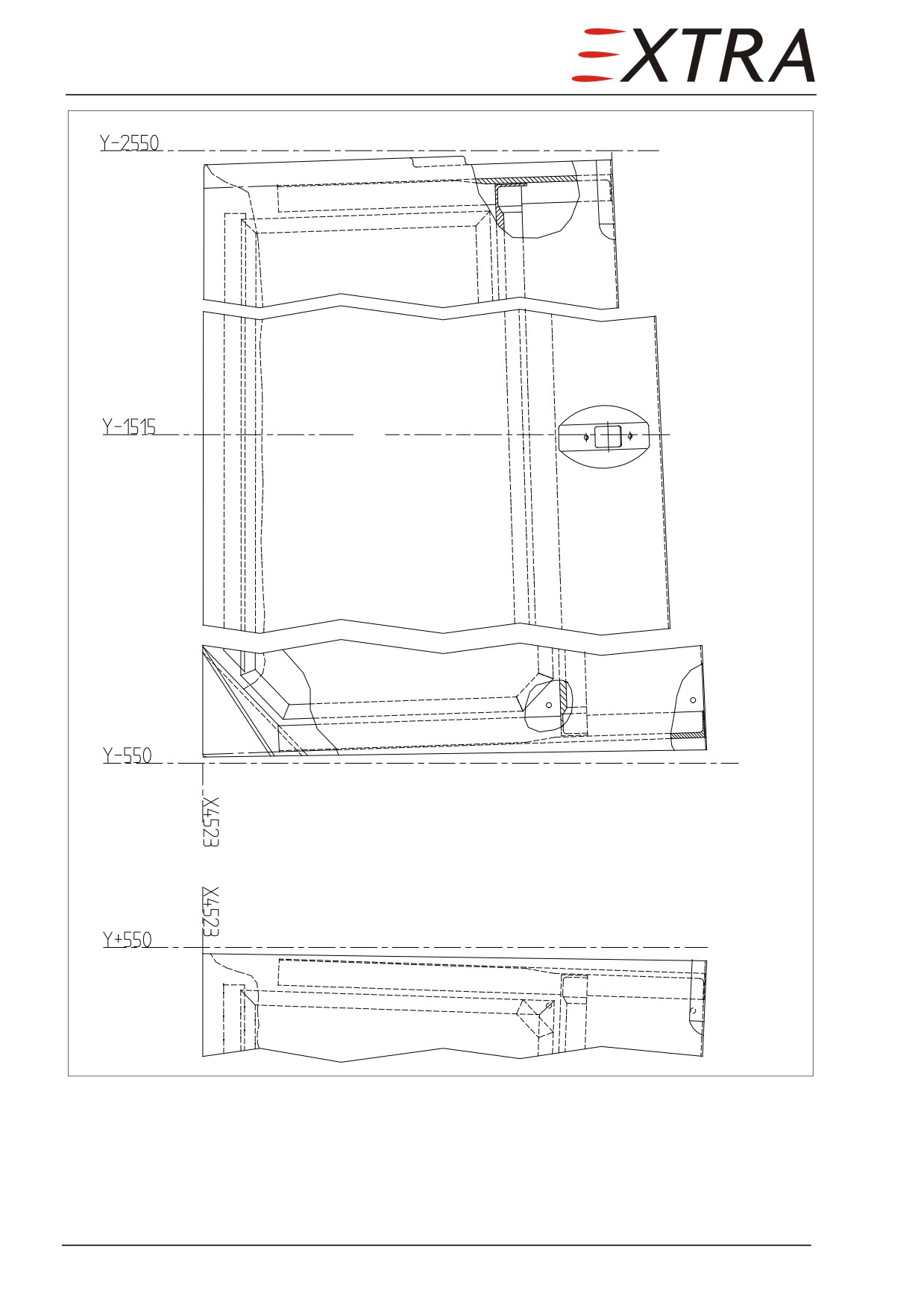
Figure 57-3
Inner Flap Structure
Page 10 57
Page Date:
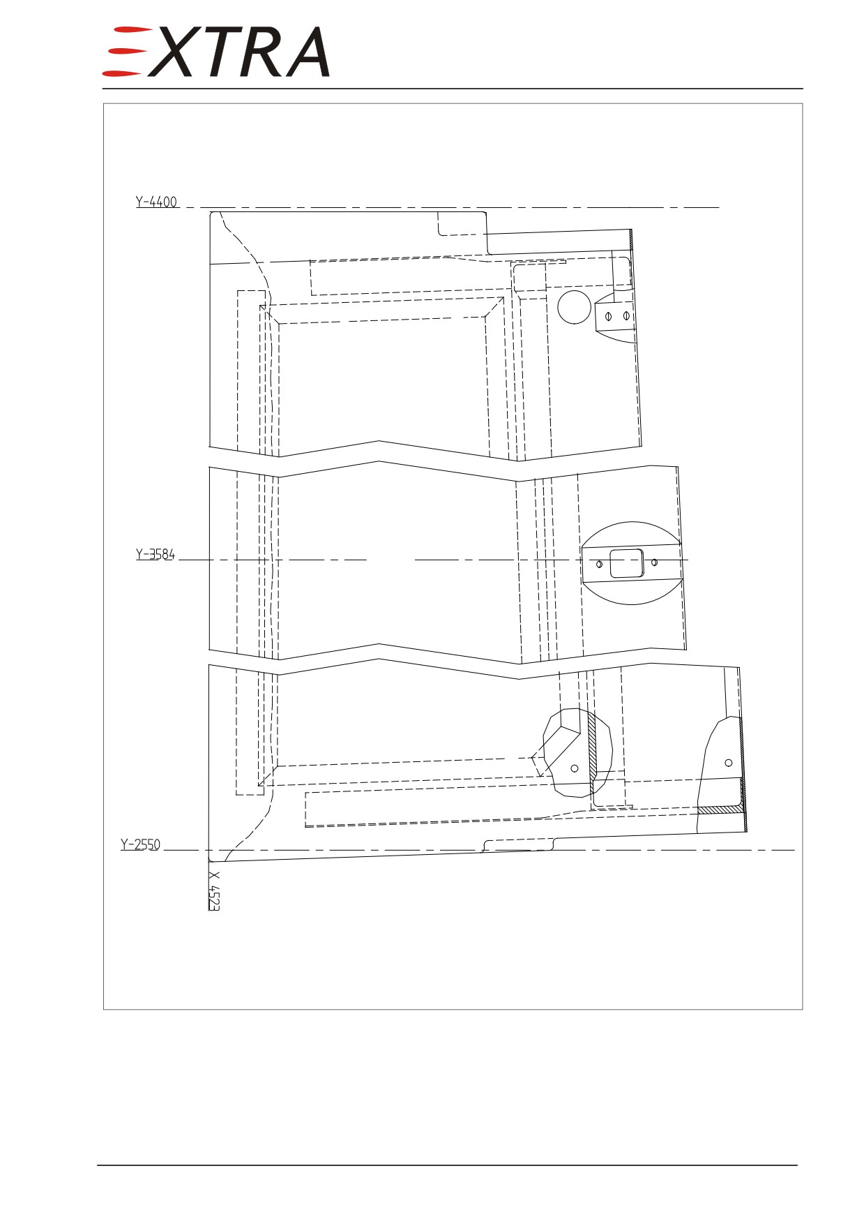
Figure 57-4
Outer Flap Structure
57 Page 11
57-60-00
AILERONS
Description
Refer to Figure 57-5. The ailerons are of one spar dual torsion box all-CFRP-
composite construction. The aileron hinge line is positioned 70% of the wing
chord. To prevent flutter they are mass balanced in the overhanging leading
edge.
Removal/Installation
For removal and installation refer to Chapter 27
Page 12 57
Page Date
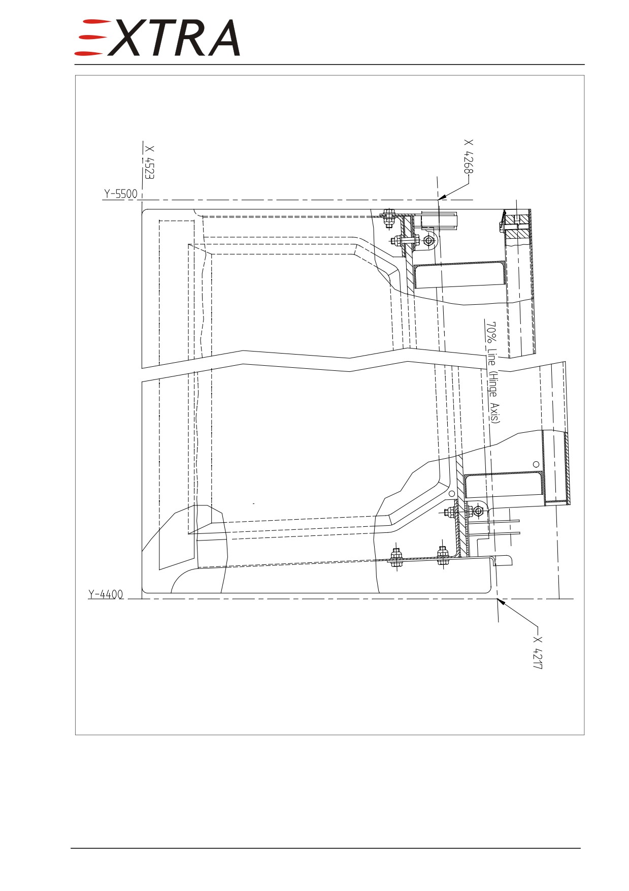
Figure 57-5
Aileron Structure
57 Page 13
Chapter 61
Propeller
61 Page 1
Table of Contents
61-00-00
GENERAL
3
Description
3
Troubleshooting
4
Page 2 61
61-00-00
GENERAL
Description
The EXTRA 500 is equipped with a MTV-5-1-D-C-F-R(A)/CFR210-56
5-blade propeller. The MTV-propeller has a laminated wood composite
structure encased by an epoxy-fiber glass cover with metal tipping.
The governor regulates the blade pitch for a constant RPM.
Internal springs and counter-weights push the blades in high pitch (feather
position). Oil pressure pushes them in low pitch and reverse position. Thus in
case of an engine failure the propeller will be in feather position (low drag
configuration).
The propeller is equipped with electrically heated de-icers, bonded to the
blades. The electric power is provided by slip rings and a stationary brush
assembly.
Refer to Chapter 30-60 for further information concerning propeller icing
protection.
Control, operation and maintenance of the propeller is described in the MT -
Propeller Operation and Installation Manual E-610 (LOAP 3). Some of the
control aspects and rigging
(propeller beta control, propeller blade angle
adjust) are described in the Rolls-Royce 250-B17F Series Engine Operation
and Maintenance Manual (LOAP 1), Chapters 76-00-00 and 76-10-02.
The parts and overhaul works are listed and described in the MT - Propeller
Overhaul and Parts List E-220 (LOAP 5).
For more information consult the propeller manufacturer.
For dynamically balancing the propeller refer to Rolls-Royce 250-B17F Series
Engine Operation and Maintenance Manual (LOAP 1), Chapter 72-00-00,
Page 503.
Page Date:
61 Page 3
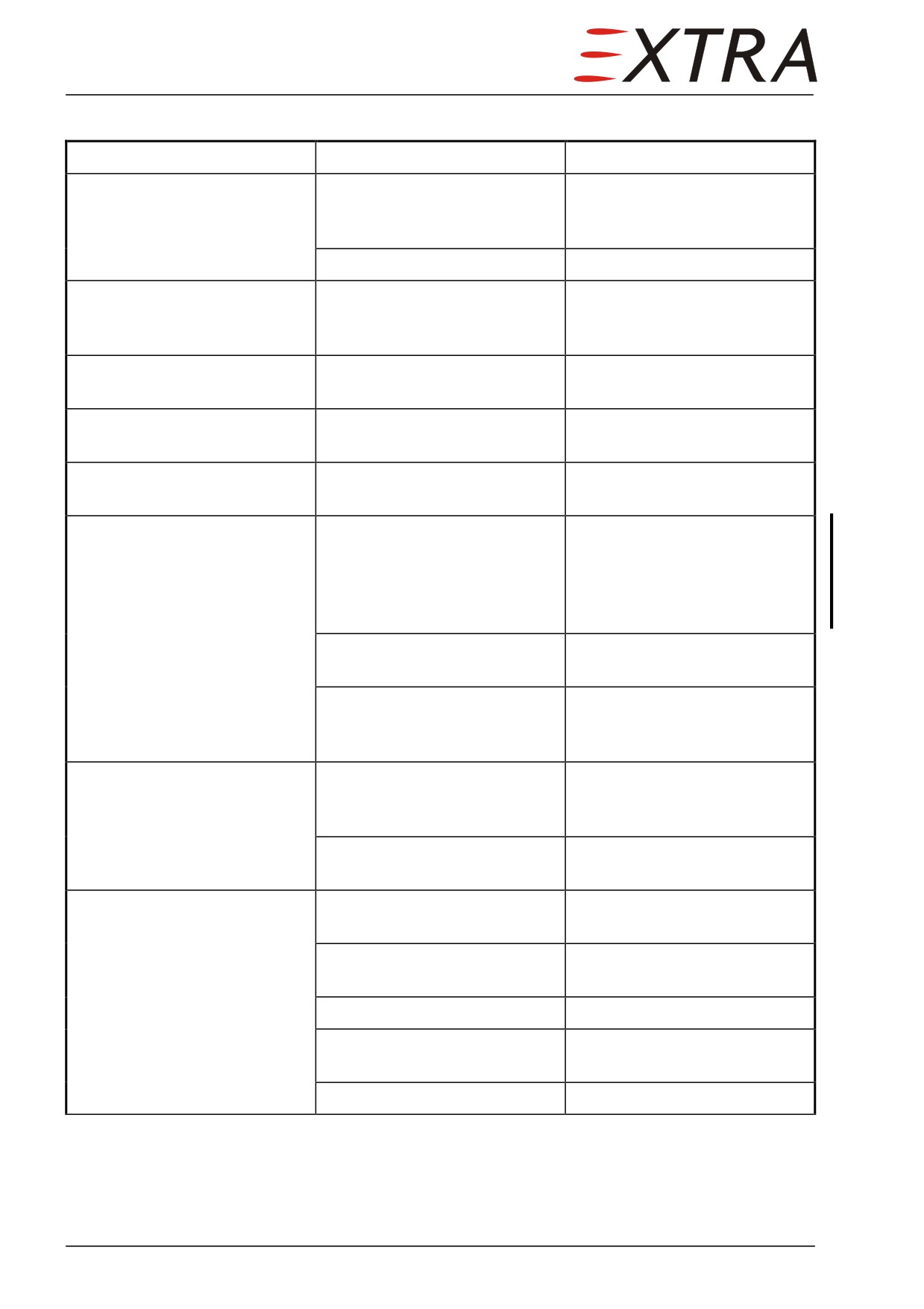
Troubleshooting
Complaint
Possible Cause
Remedy
Excessive vibration, rough
Propeller unbalanced
Dynamically balance propeller
running
according to engine
manufacturer’s information
Icing
Switch on propeller de-icing
Blade damage
Foreign object damage
Repair or replace propeller
according to propeller
manufacturer’s instruction
Spinner or backplate damage
Foreign object or handling
Replace by airworthy parts
damage
Blade play
Blade bearing loose
Refer to propeller
manufacturer’s instruction
Hub damage
Propeller loose on crankshaft
Refer to engine and propeller
manufacturer’s instruction
Improper RPM
Propeller pitch setting out of
Adjust propeller governor
limits
speed stop acc. to engine
manufacturer's instruction
(LOAP 1), Chapter 73-20-01,
Page 203.
Governor setting out of limits
Refer to engine
manufacturer’s instruction
Malfunctioning propeller
Replace governor, for
governor
adjustment see engine
manufacturer’s instruction
Sluggish RPM change
Cold oil
Run engine until normal
operating oil temperature is
reached
Propeller pitch control
Refer to propeller
mechanism defective on
manufacturer’s instruction
Surging RPM
Trapped air in propeller piston
Cycle propeller control to
bleed trapped air
Engine power surge
Refer to engine section,
chapter 72
Abrupt control movement
Move controls carefully
Propeller pitch control
Refer to propeller
mechanism defective
manufacturer’s instruction
Governor defective
Replace governor
Page 4 61
Page Date:
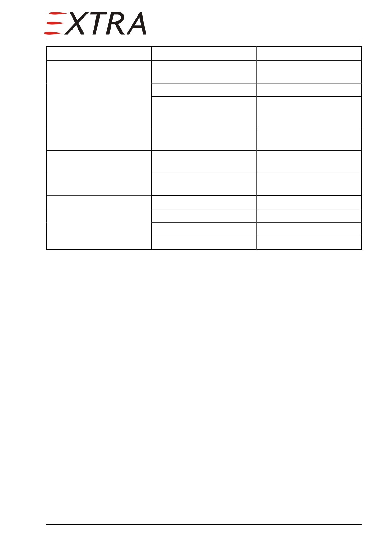
Complaint
Possible Cause
Remedy
RPM changes at constant
Excessive hub friction
Refer to propeller
propeller setting
manufacturer’s instruction
Excessive governor friction
Replace governor
Oil leakage or hot oil
Check for leaks, replace
gasket, decrease oil
temperature
Propeller pitch control
Refer to propeller
mechanism defective
manufacturer’s instruction
Oil leakage
Damaged gasket
Replace gasket or repair
propeller
Loss of blade bearing grease
Refer to propeller
manufacturer’s instruction
No effect of condition lever
Connection detached
Restore connection
control
RPM control bracket defective
Restore or replace bracket
Bowden cable broken
Replace Bowden cable
Bowden cable binding
Replace Bowden cable
61 Page 5
Chapter 71
Power Plant
71 Page 1
Table of Contents
71-00-00
GENERAL
3
Troubleshooting
.................................................................................................. 3
71-10-01
Engine
................................................................................................................ 3
Removal
.............................................................................................................. 3
Installation
.......................................................................................................... 5
71-10-00
Cowling
.............................................................................................................. 6
71-10-01
Upper Left Cowling
.......................................................................................... 6
Removal
.............................................................................................................. 6
Installation
.......................................................................................................... 6
71-10-02
Upper Right Cowling........................................................................................ 7
Removal
.............................................................................................................. 7
Installation
.......................................................................................................... 7
71-10-03
Lower Cowling
.................................................................................................. 7
Removal/Installation
........................................................................................... 7
71-20-00
ENGINE MOUNT
............................................................................................ 8
Description.......................................................................................................... 8
71-20-01
Shock-Mount
..................................................................................................... 8
Removal
.............................................................................................................. 8
Installation
.......................................................................................................... 9
71-60-00
AIR INTAKES
................................................................................................ 10
Description........................................................................................................ 10
71-60-01
Engine Inlet
..................................................................................................... 10
Removal/Installation
......................................................................................... 10
71-70-00
ENGINE DRAINS
.......................................................................................... 11
Description........................................................................................................ 11
71-70-01
Engine Fire-Shield Drains.............................................................................. 11
Description........................................................................................................ 11
Removal/Installation
......................................................................................... 11
71-70-02
Engine Combustion Chamber Drain
............................................................ 11
Description........................................................................................................ 11
Removal/Installation
......................................................................................... 11
71-70-03
Engine Drain Manifold
12
Description........................................................................................................ 12
Removal/Installation
......................................................................................... 12
71-70-04
Overboard Line............................................................................................... 12
Description........................................................................................................ 12
Removal/Installation
......................................................................................... 12
Page 2 71
71-00-00
GENERAL
For specific repair and replacement information refer to Rolls-Royce 250-B17F
Series Engine Operation and Maintenance Manual (LOAP 1).
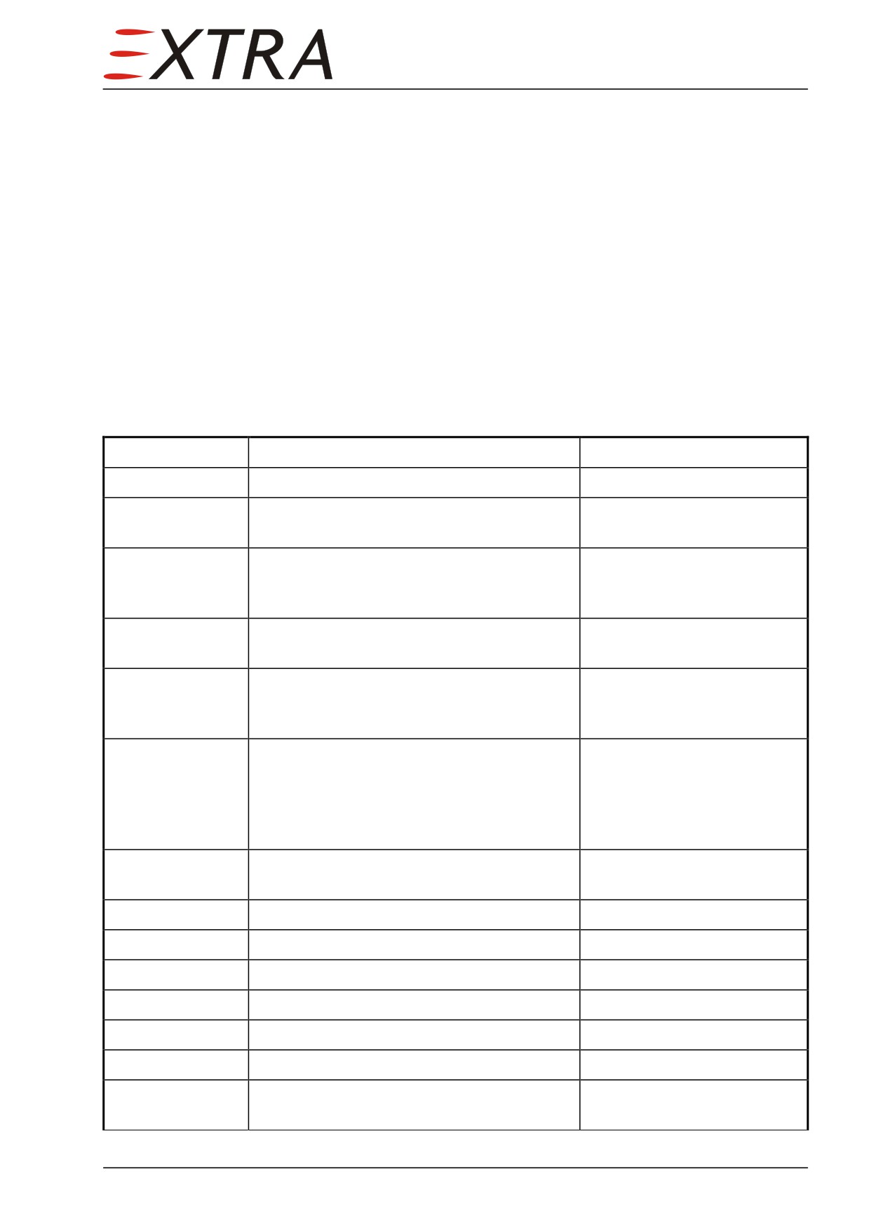
Troubleshooting
For troubleshooting refer to Table 101 of the above-mentioned Manual.
71-10-01
Engine
Removal
Detail Steps/Work Items
Key Items
1
Set FUEL SELECTOR VALVE to OFF.
2
Switch off all electrical power, disconnect
battery.
3
As the balance of the aircraft will
dramatically change, put a support under the
tail.
4
Remove upper and lower cowlings.
Refer to subjects 71-10-01, -
02, -03
5
Remove propeller.
Refer to MT - Propeller
Operation and Installation
Manual E-610 (LOAP 3)
6
Remove beta-valve.
Refer to Rolls-Royce 250-
B17F Series Engine
Operation and Maintenance
Manual (LOAP 1), Chapter
76-10-02
7
Remove brush-block including mounting
from engine.
8
Remove engine inlet.
Refer to Subject 71-60-01
9
Remove exhaust stacks.
Refer to Ch. 78-00-01/02
10
Remove bleed air hoses.
11
Remove two sonic venturis. Plug holes.
12
Remove starter generator.
Refer to Chapter 24-30-10
13
Disconnect power line ignition.
14
Disconnect the bonding braid on the ignition
exciter attachment bolt.
71 Page 3
Detail Steps/Work Items
Key Items
15
Disconnect the electrical wiring from the
chip detection sensors.
Fuel may be pressurized (30 psi max). Fuel may spill. Protect yourself
WARNING
and catch spilling fuel in a suitable container.
16
Disconnect fuel hose at engine fuel inlet.
Plug hole and line.
17
Remove fuel manifold from aft engine fire-
shield.
18
Disconnect the fuel pressure sense line and
fitting. Plug hole and line.
19
Remove fuel drain lines from engine fire-
shield.
20
Remove fuel drain hose from combustion
chamber. Plug fitting.
21
Remove engine control mounting bracket
Refer to Chapter 76-10-01
22
Remove gearbox vent line and fitting from
engine. Plug hole and line.
23
Disconnect thermocouple wiring from
Refer to Chapter 77-20-01
terminal block on RH engine fire-shield.
24
Remove terminal block from RH engine
Refer to Chapter 77-20-02
fire-shield.
25
Remove oil vent line and fitting from
engine. Plug hole and line.
26
Remove oil vent ‘check valve T’ and
connecting hoses.
27
Remove TRQ sense line and fitting. Plug
RH forward gearbox
hole and line.
28
Remove oil pressure sense line and fitting.
LH forward gearbox
Plug hole and line.
29
Drain oil system.
Refer to Chapter 79-00-00
30
Remove ‘oil in’ hose.
31
Disconnect electrical connector oil
temperature sensor.
32
Loosen counter nut of ‘oil in’ fitting,
remove fitting. Plug hole and line.
33
Remove ‘oil out’ tube and fitting. Plug
check valve and line.
34
Remove external scavenge oil filter.
Refer to Chapter 79-20-01
35
Disconnect electrical connectors of engine
above engine fire-shield
anti-ice and propeller overspeed test.
Page 4 71
Detail Steps/Work Items
Key Items
36
Disconnect electrical wiring standby
alternator.
37
Disconnect lightning cable and bonding
braid from standby alternator RH
attachment stud.
38
Check engine is fully disconnected except
main attachment points.
39
Remove upper main attachment bolt.
Mark bolts and nuts as used.
40
Hoist engine slightly though upper shock-
Hoisting structure must be
mount bolt hole.
able to carry at least 150 kg
(300 lbs). Align hoist exactly
above shock-mount.
41
Support the engine at the combustion
chamber.
42
Remove both side main attachment bolts.
Mark bolts and nuts as used.
43
Lower engine 5-10cm (2-4 inch) and pull
the engine out straight forward.
44
Remove the side shock-mounts.
Refer to Subject 71-20-01
45
Perform preservation and storage
Refer to Rolls-Royce 250-
precautions.
B17F Series Engine
Operation and Maintenance
Manual (LOAP 1)
46
Remove upper shock-mount when engine is
Refer to Subject 71-20-01
securely stored.
47
Remove standby alternator from engine
Refer to Chapter 24-30-20
48
Remove gas generator turbine tachometer
Refer to Chapter 77-00-01
49
Remove propeller/power turbine RPM
Refer to Chapter 77-10-02
sensor.
Installation
Detail Steps/Work Items
Key Items
1
Remove engine from container.
Refer to Engine Maintenance
Manual
2
Install in reverse sequence of removal.
Observe the following steps.
3
Torque main attachment bolts 32 Nm
(283 lbs-inch), use new bolts and nuts
4
Use new packings where necessary.
5
Perform engine control rigging check
Refer to Chapter 76-00-00
71 Page 5
Detail Steps/Work Items
Key Items
NOTE
The propeller must be dynamically balanced if a new engine or new
propeller is installed. Refer to Rolls-Royce
250-B17F Series Engine
Operation and Maintenance Manual (LOAP 1)
6
Perform applicable engine run tests.
Refer to Rolls-Royce 250-
B17F Series Engine
Operation and Maintenance
Manual (LOAP 1), Chapter
72-00-00
7
Perform engine indication check (TOT only)
Refer to Chapter 77-00-00
71-10-00
Cowling
The EXTRA 500 cowling consists of three parts:
• Upper left cowling
• Upper right cowling
• Lower cowling
The upper cowlings are attached by means of cam-locks. The lower cowling is
attached with bolts.
71-10-01
Upper Left Cowling
Removal
Detail Steps/Work Items
Key Items
1
Unlock all cam-locks.
24 cam-locks
2
Raise and remove cowling.
Installation
Detail Steps/Work Items
Key Items
1
Set cowling aircraft.
2
Fasten all cam-locks.
3
Check all cam-locks are engaged by firmly
hitting the cowling near attachments.
Page 6 71
71-10-02
Upper Right Cowling
Removal
Detail Steps/Work Items
Key Items
1
Remove upper left cowling first.
2
Remove all cam-locks.
14 cam-locks
3
Raise and remove cowling
Installation
Detail Steps/Work Items
Key Items
1
Set cowling aircraft.
2
Fasten all cam-locks.
14 cam-locks
3
Check all cam-locks are engaged by firmly
hitting the cowling near attachments.
71-10-03
Lower Cowling
Removal/Installation
Detail Steps/Work Items
Key Items
1
Remove upper cowlings first.
Refer to Subj. 71-10-01/02
2
Disconnect landing light bulkhead
connector.
3
Remove bridge tube on forward part of
4 bolts
cowling.
4
Remove lower cowling aft attaching bolts.
7 bolts
5
Remove lower cowling as one piece.
6
Disassemble lower cowling if applicable.
4 bolts
7
Install in reverse order of removal.
Make sure that all rubber
seals fit properly at intake.
71 Page 7
71-20-00
ENGINE MOUNT
Description
The steel tube designed engine mount supports the engine and attaches it to the
airframe. It is mounted to the airframe at six points with mount supports, using
bolts, washers and self-locking type nuts.
71-20-01
Shock-Mount
The engine is attached to the engine mount at three points. Each point
incorporates a vibration isolator type shock mount assembly capable of
sustaining operational loads and providing absorption of engine vibrations.
They use the upper and side mounting pads of the engine.
For humidity & corrosion prevention MASTINOX is applied to the lower
shock-mount surface (contact area to the engine mounting pad).
Removal
It is assumed that the engine is not installed in the aircraft (otherwise refer to
Subject 71-00-01).
Never remove a shock-mount while the engine is installed.
CAUTION
Detail Steps/Work Items
Key Items
MASTINOX is highly flammable, toxic and dangerous for the
WARNING
environment. It may cause cancer and is harmful by inhalation, in
contact with skin and if swallowed. Toxic to aquatic organisms, may
cause long-term adverse effects in the aquatic environment.
Use applicable gloves and respirator mask.
1
Remove lock-wire.
2
Unscrew bolts.
3 bolts
3
Remove shock-mount.
Page 8 71
Installation
Detail Steps/Work Items
Key Items
MASTINOX is highly flammable, toxic and dangerous for the
WARNING
environment. May cause cancer. Harmful by inhalation, in contact with
skin and if swallowed. Toxic to aquatic organisms, may cause long-term
adverse effects in the aquatic environment.
Use applicable gloves and respirator mask.
1
Apply MASTINOX on the lower surface of
the shock-mount.
2
Place the shock-mount in position, hand
3 bolts
tighten bolts.
3
Torque all three bolts
11.9- 13.0 Nm
(105-115 lbs-inch)
4
Lock-wire bolts against each other.
71 Page 9
71-60-00
AIR INTAKES
Description
The EXTRA 500 has an exhaust heated engine air inlet. It is mounted on the
engine compressor flange.
71-60-01
Engine Inlet
Removal/Installation
Detail Steps/Work Items
Key Items
1
Remove the RH exhaust stack.
Refer to Chapter 78-00-02.
2
Unscrew the RH helical metal hose from the
inlet.
3
Remove inlet.
12 bolts
4
Unscrew the inlet from the LH helical metal
hose.
5
Install in reverse sequence of removal.
Observe the following hint.
IMPORTANT
Make sure while setting the length of the helical metallic hose that the
forces on the engine flange while attaching the exhaust stack must be
minimal. Screw in the helical metallic hose minimum one full turn on
each side. Maximum two full turns each side are possible.
Page 10 71
71-70-00
ENGINE DRAINS
Description
The EXTRA 500 engine has 5 drain fittings. Fuel, oil or other fluids are
collected in the engine manifold and drained overboard.
71-70-01
Engine Fire-Shield Drains
Description
The engine fire-shield drains are located on the left and right side (two each) of
the engine fire-shield. They are connected by aluminum tubing and connected
to the drain manifold by hoses.
Removal/Installation
Detail Steps/Work Items
Key Items
1
Remove LH and RH upper cowling.
Refer to Chapter 71-10-01/02
2
Disconnect hoses from drain manifold.
3
Disconnect drain lines from engine fire-
shield.
4
Install in reverse sequence of removal.
Make sure all lines are clean
71-70-02
Engine Combustion Chamber Drain
Description
In case of a false engine start, fuel may collect at the bottom of the combustion
chamber. This fuel will be drained through the combustion chamber drain hose
to the drain manifold.
Removal/Installation
Detail Steps/Work Items
Key Items
1
Remove LH upper cowling.
Refer to Chapter 71-10-01
2
Disconnect fittings of the combustion
chamber drain hose. Plug fitting.
3
Install in reverse sequence of removal.
71 Page 11
71-70-03
Engine Drain Manifold
Description
The engine drain manifold is installed at the bottom of the cowling, left
forward of the nose gear firewall.
Removal/Installation
Detail Steps/Work Items
Key Items
1
Remove LH upper cowling.
Refer to Chapter 71-10-01
2
Disconnect all hoses from engine drain
manifold.
3
Disconnect engine drain manifold from
overboard line and remove.
4
Install in reverse sequence of removal.
71-70-04
Overboard Line
Description
The overboard line is installed to the left side of the nose gear firewall.
Removal/Installation
Detail Steps/Work Items
Key Items
1
Remove LH upper cowling.
Refer to Chapter 71-10-01
2
Disconnect overboard line from engine
drain manifold.
3
Remove the two hose clamps at the nose
wheel bay firewall LH side.
4
Remove overboard line.
5
Install in reverse sequence of removal.
Observe the following
Refer to Product Label and Material Safety Data Sheet for health and
WARNING
safety information before using PR812.
6
Seal any opening in the firewall with
PR812.
Page 12 71
Chapter 73
Engine Fuel and Control
73 Page 1