Extra 500. Maintenance Manual (2012) - page 15
52-20-00
EMERGENCY EXIT
Description
In emergency case the upper door can be opened even with wing flaps down.
The upper door shall then be strongly pressed against the wing flap edge,
which will bend and thus increasing the upper door opening angle. This allows
deploying the lower part.
The middle RH side window opposite to the passenger entry door is built as an
emergency exit window. For opening the emergency exit window from outside
remove the clear plastic cover, turn the handle clockwise as marked and then
push window inside and down. For opening the emergency exit window from
inside swivel up the handle, turn the handle counterclockwise as marked and
then pull window inside and down.
52-20-01
Emergency Exit Seal
Removal/Installation
Detail Steps/Work Items
Key Items
1
Remove emergency exit.
2
Remove seal frame.
11 screws
3
Remove seal from frame.
4
Install in reverse sequence of removal.
5
Install safety wire to emergency exit handle.
Cu/Cu 0.25 x 0.25
Page 18 52
Page Date:
Chapter 55
Stabilizers
55 Page 1
Table of Contents
55-00-00
GENERAL
3
Description
3
55-10-00
HORIZONTAL STABILIZER
4
Description
4
Figure 55-1
Overview Horizontal Stabilizer
5
Removal
6
Installation
6
Figure 55-2
Trim Control Box
8
55-10-01
Horizontal Stabilizer Main Bolts
9
Inspection
9
55-20-00
ELEVATOR
10
Description
10
Figure 55-3
Elevator Control Surface (LH)
11
Figure 55-4
Elevator Control Surface (RH)
12
Figure 55-5
Elevator Trim Tab, (on RH elev. only)
13
55-30-00
VERTICAL STABILIZER
14
Description
14
55-30-01
Fin Tip
14
Removal/Installation
14
Figure 55-6
Fin Tip
15
55-40-00
RUDDER
16
Description
16
Figure 55-7
Overview Rudder Mounting
17
Figure 55-8
Bottom Rudder Mounting (including bell crank and centering device)
18
Figure 55-9
Middle and Upper Rudder Mounting
18
Page 2 55
Page Date: 9. August 2013
55-00-00
GENERAL
Description
The empennage is the element which controls the aircraft around the pitch and
yaw axis. It is a T-tail design with extended fin and fixed straight main
elements. The empennage is composed of the following elements:
• Horizontal stabilizer
• Elevator
• Vertical stabilizer
• Rudder
55 Page 3
55-10-00
HORIZONTAL STABILIZER
Description
The fixed straight tapered horizontal stabilizer has 2° anhedral. The NACA
0012 airfoil section is chosen for the horizontal stabilizer.
The elevator hinge line is positioned at 62% of the horizontal stabilizer chord.
The entire horizontal stabilizer structure is of CFRP sandwich construction
with two CFRP spars.
The horizontal stabilizer is attached to both vertical stabilizer front and rear
spar.
Page 4 55
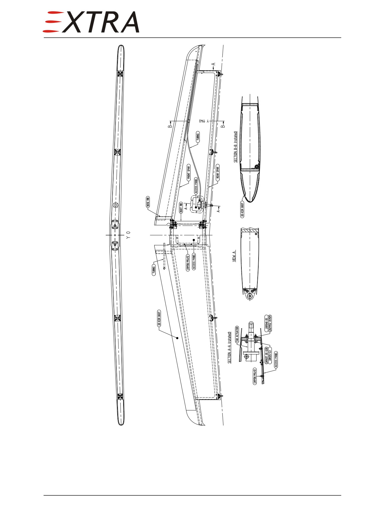
Figure 55-1
Overview Horizontal Stabilizer
55 Page 5
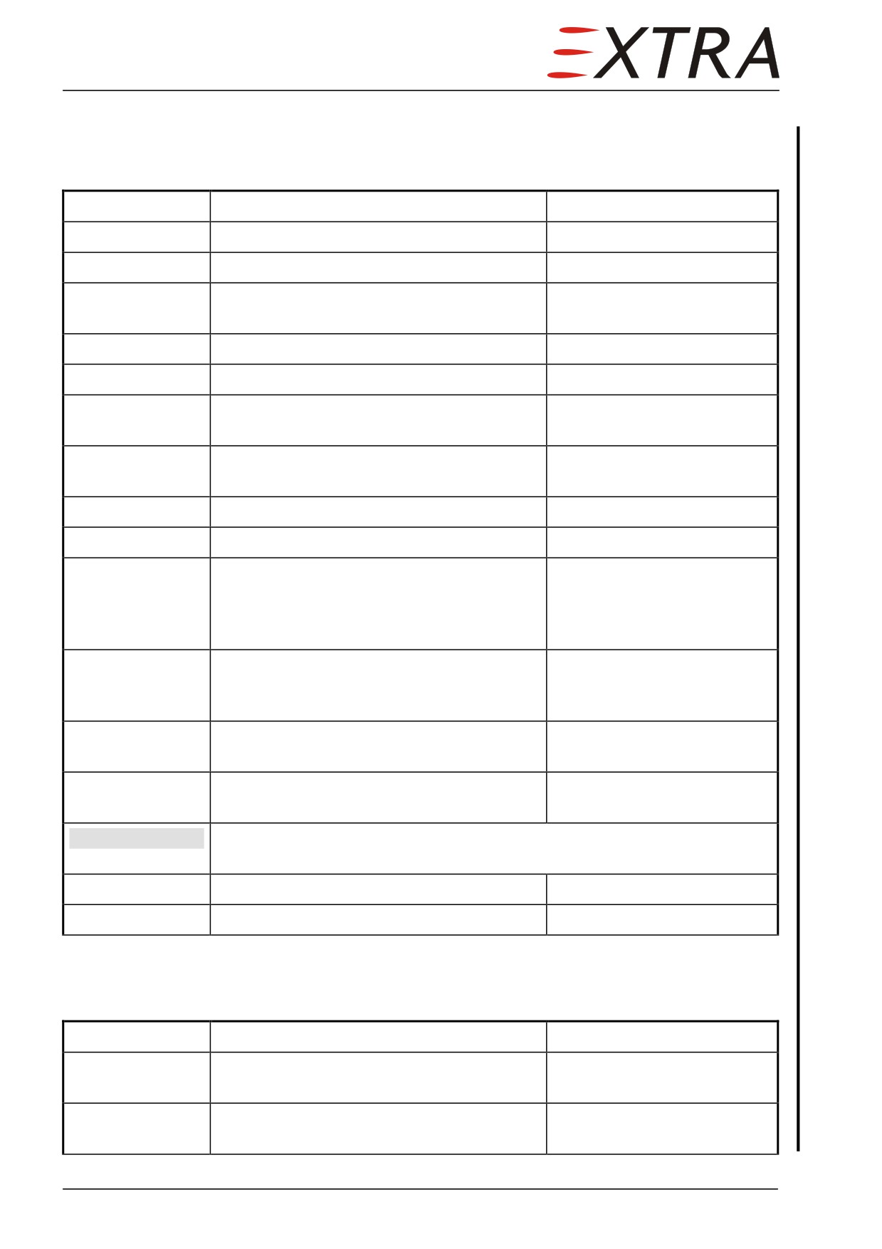
Removal
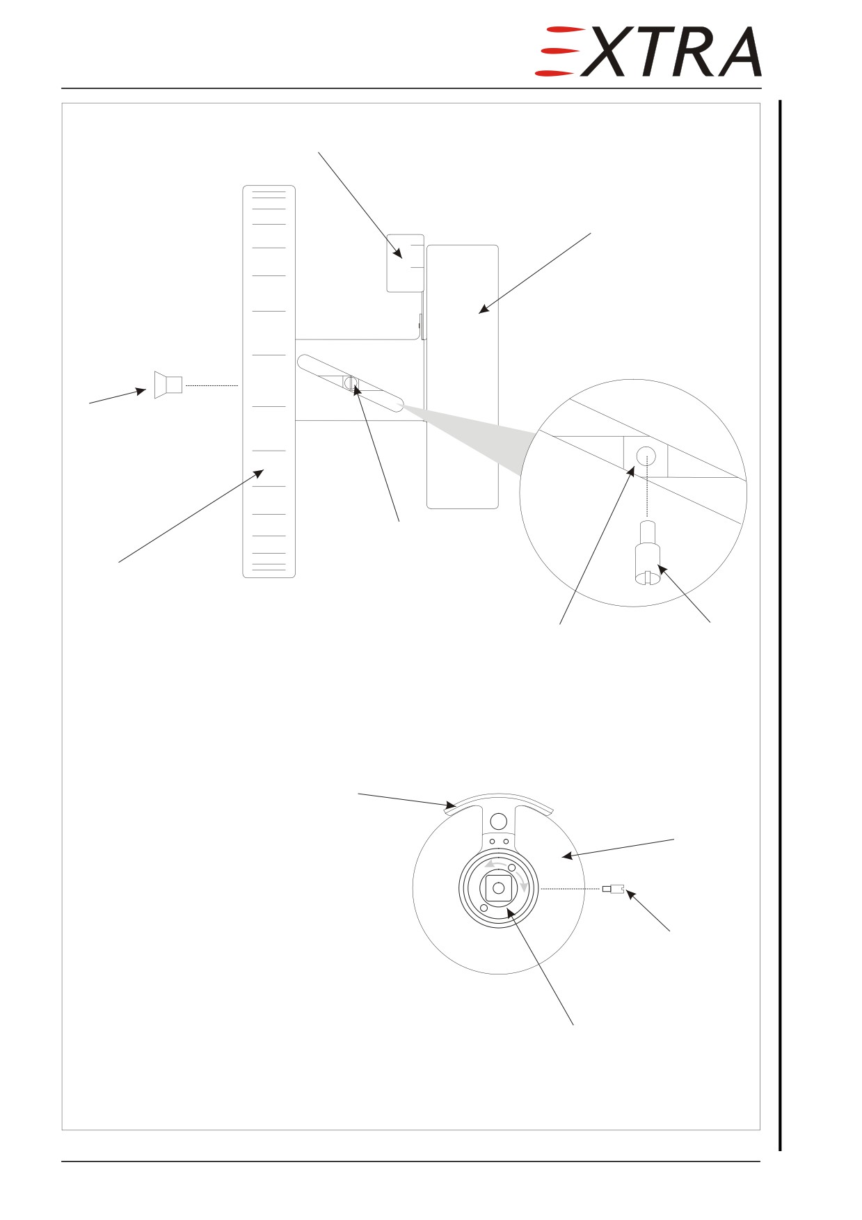
Refer to Figure 55-2.
Detail Steps/Work Items
Key Items
1
Remove fin tip.
Refer to Chapter 55-30-01
2
Remove elevator.
Refer to Chapter 27-30-00
3
Remove central horizontal stabilizer access
Refer to Chapter 51-00-01
panel
4
Remove pitch trim access panel
Refer to Chapter 51-00-01
5
Adjust pitch trim to N-position.
6
Remove upper part of middle console
Refer to Chapter 25-10-26
paneling.
7
Mark N-position of pitch trim indicator (6)
on the pitch trim control box (1) with tape.
8
Remove set screw (2).
9
Reinstall trim wheel (4) and screw (5).
10
Rotate trim wheel to the nose down
Observe movement of trim
direction until trim cable core is
tab actuator.
disconnected from the trim tab actuator in
the horizontal stabilizer.
11
Rotate a half turn further (to make sure trim
cable end is inside the trim cable flex
casing).
12
Disconnect trim cable flex casing from
actuator. Plug openings.
13
Disconnect de-icing boot pressure lines.
Plug holes.
CAUTION
Risk of main bolt thread ends damage due to hammer stroke.
Drive out main bolts using a short steel tube.
14
Remove horizontal stabilizer main bolts.
4 bolts, washers and nuts
15
Remove horizontal stabilizer.
Weight approx. 20 kg
Installation
Refer to Figure 55-2.
Detail Steps/Work Items
Key Items
1
Position horizontal stabilizer on the top of
the vertical stabilizer.
2
Install main bolts with MIL-PRF-81322.
Secure with safety wire.
Page 6 55
Page Date: 9. August 2013
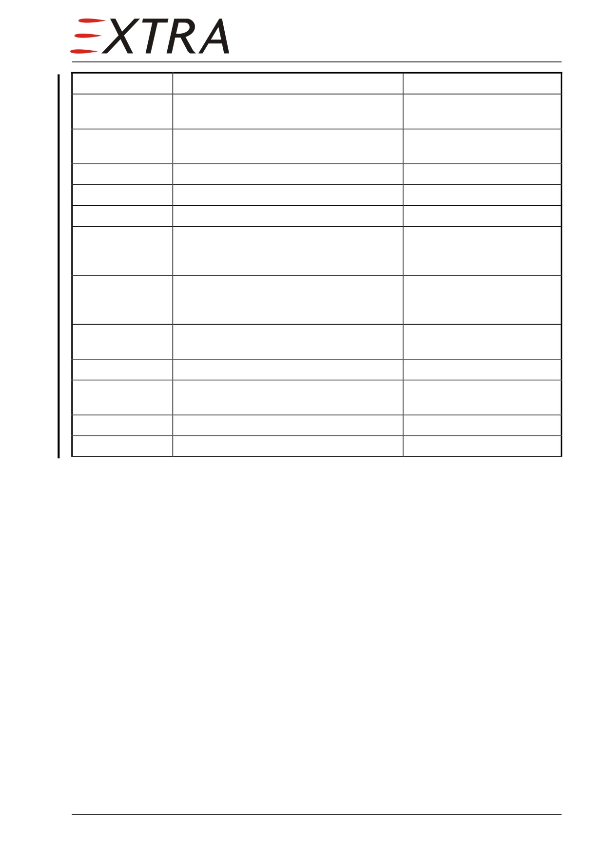
Detail Steps/Work Items
Key Items
3
Connect trim cable flex casing to actuator.
Secure with safety wire.
4
Install central horizontal stabilizer access
Refer to Chapter 51-00-01
panel
5
Connect de-icing boot pressure lines.
6
Install elevator.
Refer to Chapter 27-30-00
7
Adjust elevator to neutral.
8
Rotate trim wheel to the nose up direction
until trim tab is in straight line with elevator
and horizontal stabilizer.
9
Adjust trim indicator (6) until the N-position
match the mark on the pitch trim control box
(1).
10
Rotate round nut (3) until thread hole is
visible in the guide slot.
11
Install set screw (2) with Loctite 243.
12
Install upper part of middle console
Refer to Chapter 25-10-26
paneling.
13
Install pitch trim access panel
Refer to Chapter 51-00-01
14
Install fin tip.
Refer to Chapter 55-30-01
Page Date:9. August 2013
55 Page 7
Aft View
6
1
5
2
4
3
2
Side View (without trim wheel)
6
1
2
Legend:
1
Pitch trim control box
2
Set screw
3
Round nut
4
Trim wheel
3
5
Screw
6
Pitch trim indicator
Figure 55-2
Trim Control Box
Page 8 55
Page Date: 9. August 2013
55-10-01
Horizontal Stabilizer Main Bolts
Inspection
Detail Steps/Work Items
Key Items
1
Remove fin tip.
Refer to Chapter 55-30-01
2
Remove central horizontal stabilizer access
Refer to Chapter 51-00-01
panel
CAUTION
Risk of main bolt thread ends damage due to hammer stroke.
Drive out main bolts using a short steel tube.
3
Remove one main bolt.
4
Inspect bolt shanks for cracks, wear,
Replace if necessary
corrosion and insecurity.
5
Reinstall main bolt.
6
Follow steps 3 thru 5 for the other bolts.
7
Reinstall central horizontal stabilizer access
Refer to Chapter 51-00-01
panel.
8
Reinstall fin tip.
Refer to Chapter 55-30-01
Page Date:
55 Page 9
55-20-00
ELEVATOR
Description
Elevator
The elevator is divided in the LH & RH elevator control surface due to the
anhedral of the horizontal stabilizer and sweep back angle of the elevator hinge
line. Each elevator control surface is attached separately to the rear spar of the
horizontal stabilizer at three points. All attachment points incorporate spherical
bearings. For aerodynamical reasons the elevator control surface itself features
an shielded horn balance at the tip which incorporates the necessary mass
balance to prevent flutter. Each elevator control surface is actuated by a push
pull rod which is connected to the central cable quadrant mounted at the front
spar of the vertical stabilizer.
For elevator deflection refer to Chapter 06-10-08.
Each entire elevator control surface structure is of one spar dual torsion box
all-CFRP-composite construction.
Elevator Tab
The elevator trim is achieved by an elevator trim tab attached to the inboard
trailing edge of the right elevator with a full length piano-type hinge. The trim
tab is actuated by a fail safe push pull rod which is attached to a jack screw
type actuator in the horizontal stabilizer.
For elevator trim tab deflection refer to Chapter 06-10-08.
Page 10 55
Page Date: 9. August 2013
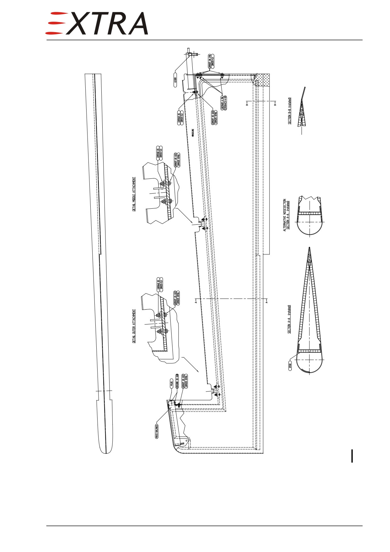
Figure 55-3
Elevator Control Surface (LH)
Page Date:
55 Page 11
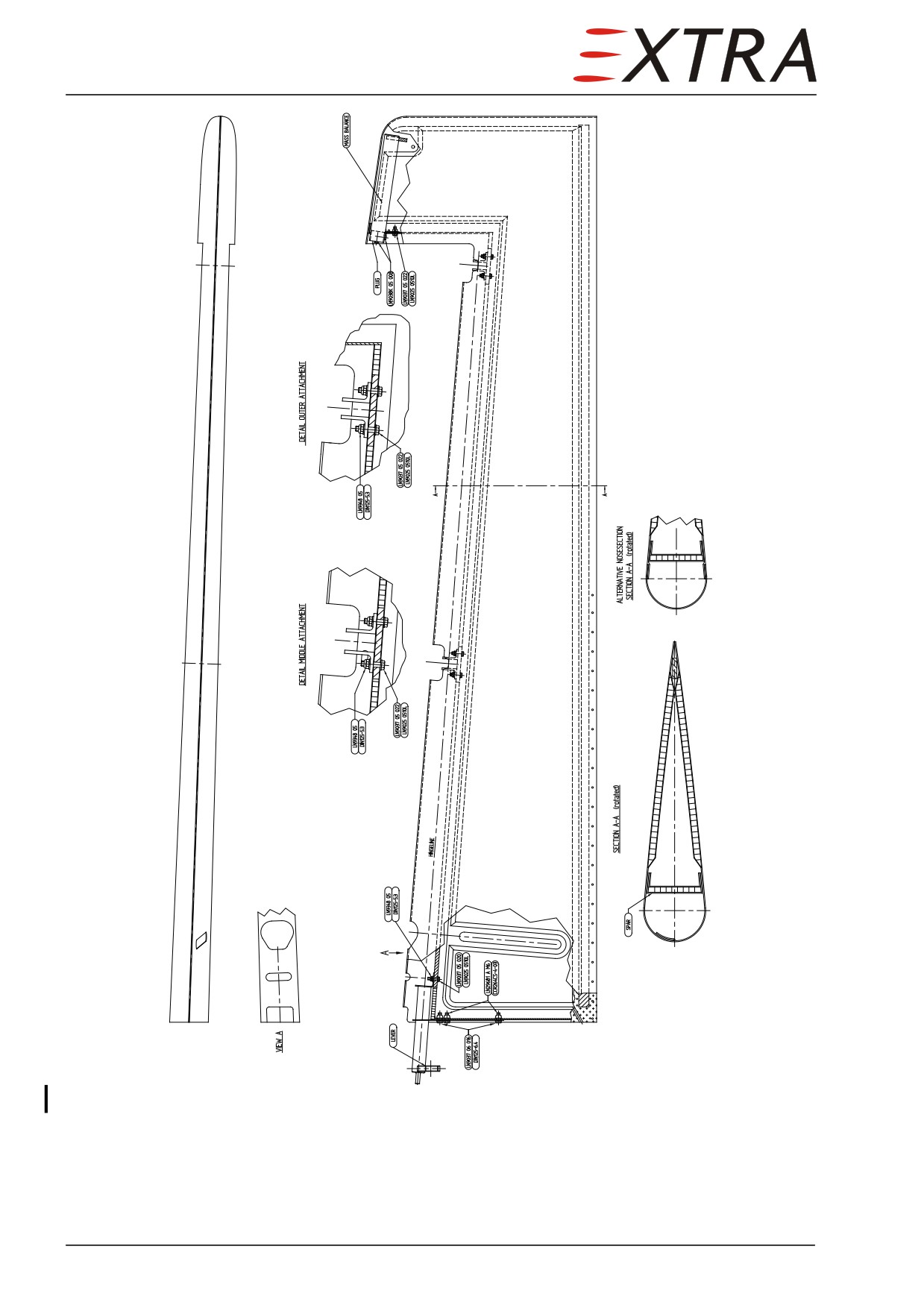
Figure 55-4
Elevator Control Surface (RH)
Page 12 55
Page Date: 9. August 2013
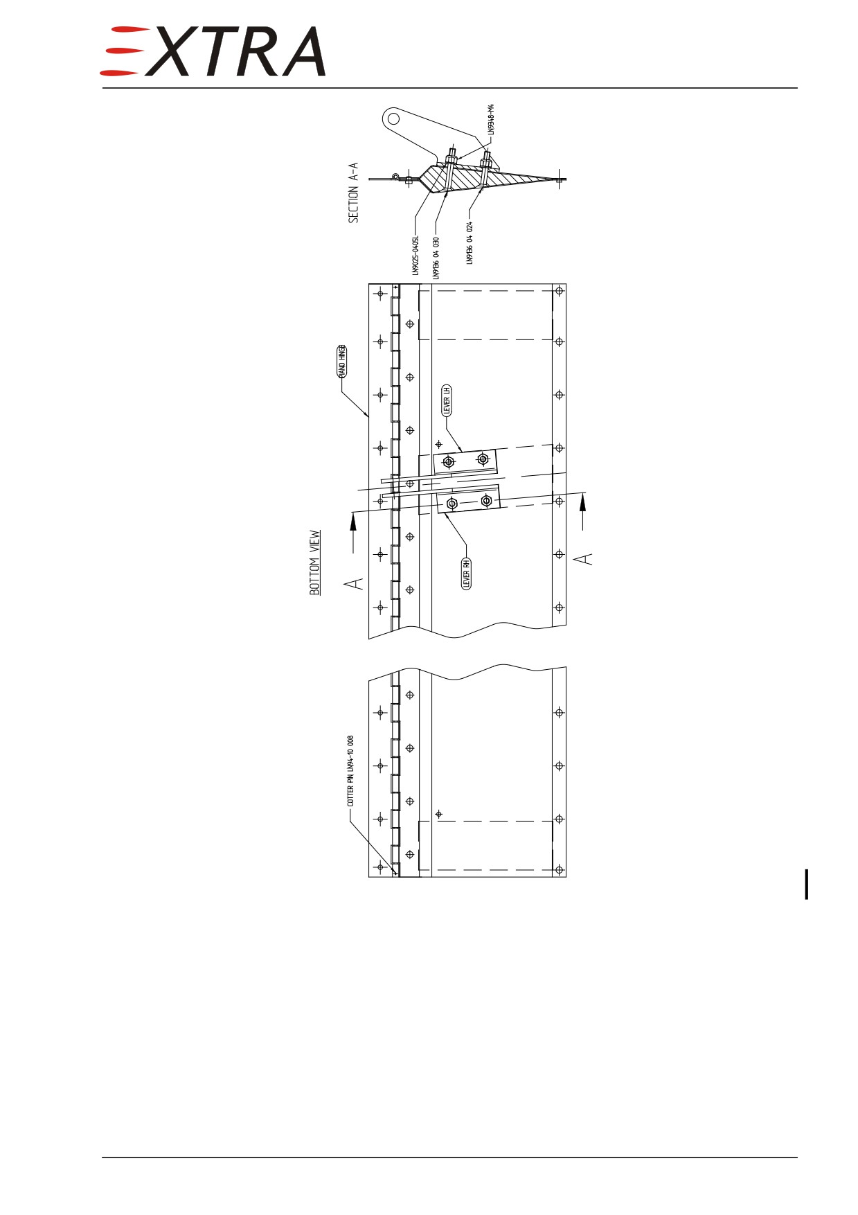
Figure 55-5
Elevator Trim Tab, (on RH elev. only)
Page Date:
55 Page 13
55-30-00
VERTICAL STABILIZER
Description
The vertical stabilizer consists of two parts. The lower part reaches to the
horizontal stabilizer and is structurally integrated with the fuselage. The upper
part (fin tip) is attached to the lower part with bolts.
The vertical fin has the cambered NACA 2412 profile at the root gradually
changing in the NACA 0012 airfoil section at the horizontal stabilizer. This is
to counter the propeller induced cross flow. The fin tip is a NACA 0012 airfoil.
The entire vertical stabilizer structure is of CFRP sandwich construction with
two CFRP spars. The shell of the lower part of the vertical stabilizer is a part of
the fuselage shell.
55-30-01
Fin Tip
Removal/Installation
Refer to Figure 55-6.
Detail Steps/Work Items
Key Items
High voltage can cause injuries!
WARNING
Pull out the STROBE-LT circuit breaker and let bleed down power supply
for 10 minutes after shutting off before beginning any work on the
strobe light systems.
2
Remove LH and RH gap fairing.
Refer to Chapter 51-00-01
3
Remove fin tip attaching bolts.
10 bolts
4
Lift fin tip some centimeters.
5
Disconnect strobe light power supply
In the front section
connectors.
6
Disconnect NAV antenna wiring BNC
From serial N° 1003
connector.
7
Remove fin tip.
Reverse polarity of the input power, for just an instant, will
CAUTION
permanently damage power supply. This damage is sometimes not
immediately apparent, but will cause failure later on. Black lead is
negative.
8
Install in reverse sequence of removal.
Page 14 55
Page Date: 9. August 2013
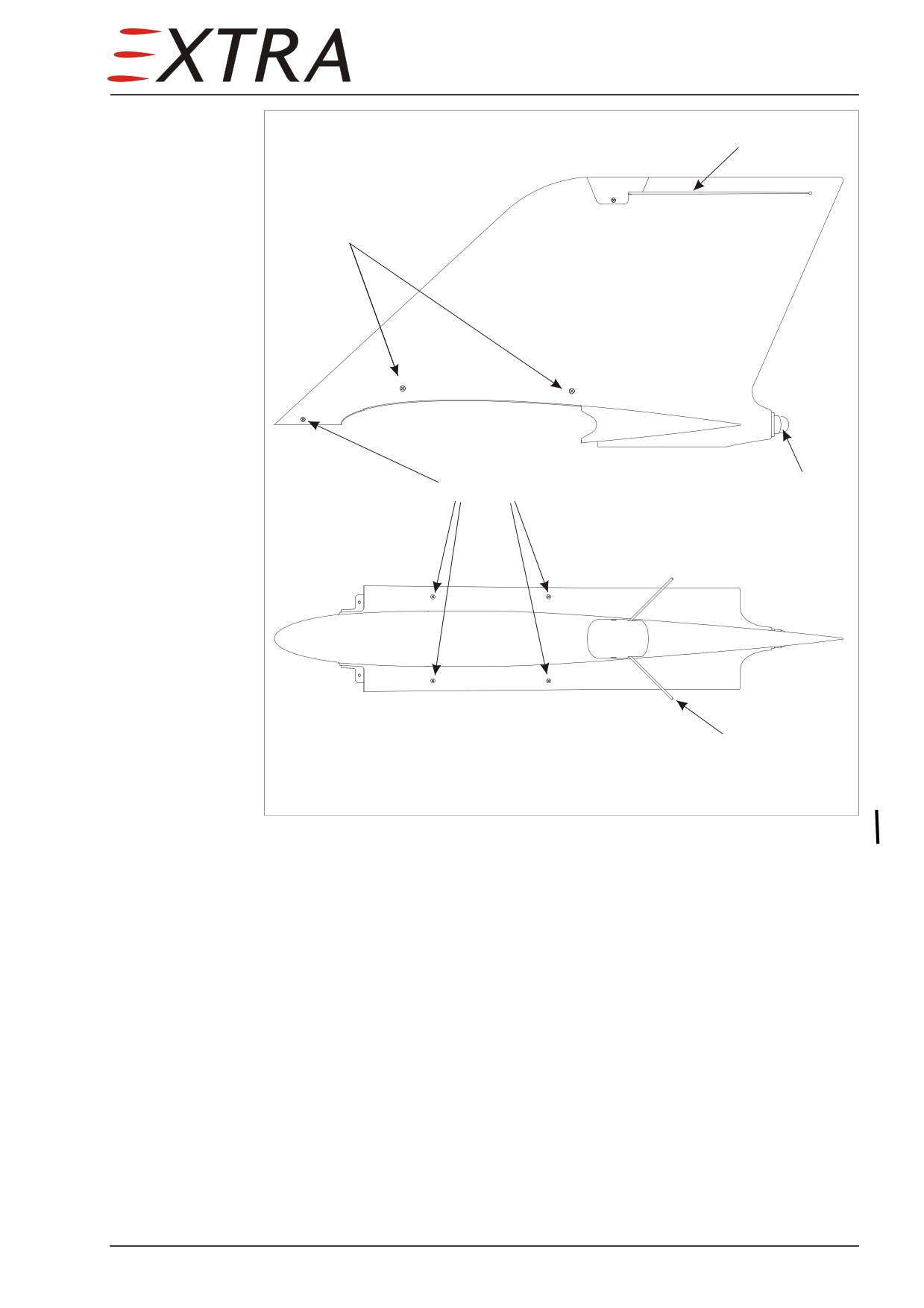
Side View
NAV antenna*
LN bolts
Strobe light
MS bolts
Top View
NAV antenna*
*) NAV antenna installed on fin tip from serial N° 1003
Figure 55-6
Fin Tip
Page Date:
55 Page 15
55-40-00
RUDDER
Description
The rudder hinge line is positioned at 73% of the vertical stabilizer chord.
To prevent flutter the rudder is mass balanced at the upper overhanging circular
nose section.
The entire rudder structure is of one spar dual torsion box all-CFRP-composite
construction.
The rudder is attached to the vertical stabilizer rear spar at three points. All
hinges incorporate ball bearings. It is actuated by a bell crank attached to the
bottom.
A spring loaded centering device is located at the rudder actuation bell crank,
which keeps the rudder in the neutral position and enlarges the control forces.
For rudder deflection refer to Chapter 06-10-08.
Page 16 55
Page Date: 9. August 2013
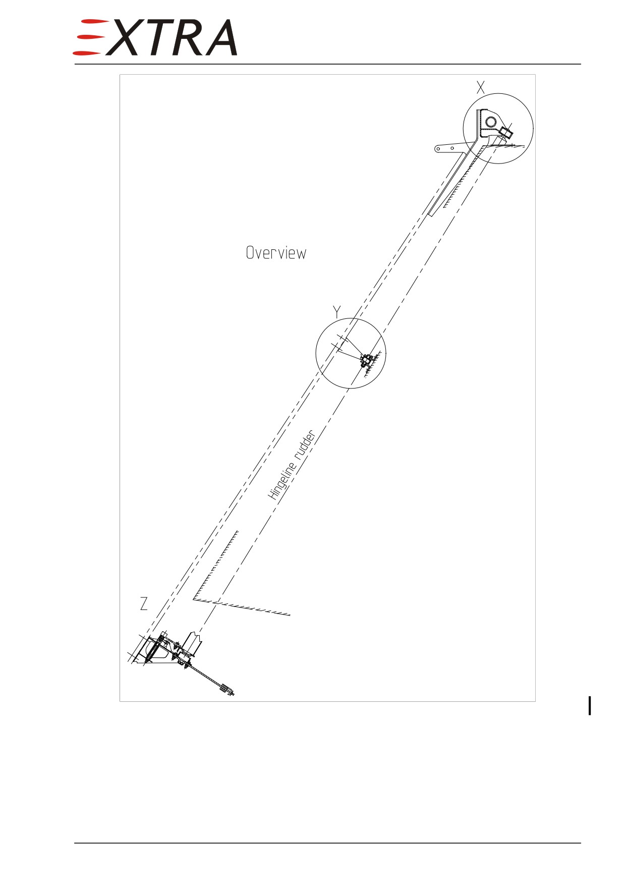
Figure 55-7
Overview Rudder Mounting
Page Date:
55 Page 17
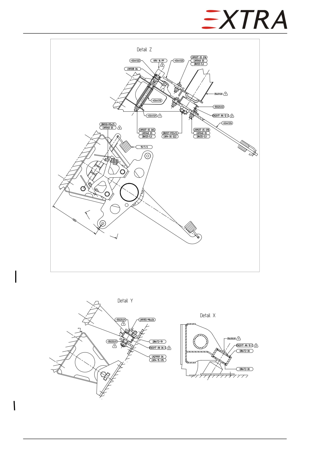
*) For rudder deflection refer to Chapter 06-10-08
Figure 55-8
Bottom Rudder Mounting (including bell crank and centering device)
Figure 55-9
Middle and Upper Rudder Mounting
Page 18 55
Page Date: 9. August 2013
Notes (∆) on Figure 55-8 and Figure 55-9:
Note 1: Install bushings EA-35020.01 and -45441.01 as well as pin of -
35631.00 and -35633 with grease according MIL-G-81322D (e.g. Aeroshell
Grease 22C)
Note 2: Install spherical bearings and retaining rings with corrosion protectant
according LN9368-5903 (e.g. Mastinox 6856H)
Note 3: deleted in drawing
Note 4: Adjust bolts DIN933-M5x25 for correct rudder deflection (refer to
Chapter 06-10-08).
Page Date:
55 Page 19
Chapter 56
Windows
56 Page 1
TABLE OF CONTENTS
56-00-00
GENERAL
3
Description
3
56-10-00
FLIGHT COMPARTMENT
4
56-10-01
Windshield
4
Description
4
Removal
4
Installation
7
56-20-00
CABIN
11
56-20-10
Cabin Windows
11
Description
11
Removal
11
Installation
12
Page 2 56
Page Date: 9. August 2013
56-00-00
GENERAL
Description
For the EXTRA 500 windows two materials are used for the windows of the
pressure cabin:
Stretched acrylic material (MIL-P-25690)
Cast acrylic material (MIL-P-8184)
The windows are highly stressed members of the pressure vessel. Scratches
have to be avoided. If cracks are detected, the window has to be replaced
before the aircraft is operated in pressurized mode again.
The middle window on the right side of the passenger compartment is designed
as emergency exit. Refer to Chapter 52-20-00 for further information.
Page Date:
56 Page 3
56-10-00
FLIGHT COMPARTMENT
56-10-01
Windshield
Description
The EXTRA 500 is equipped with a two piece windshield divided by a
structural middle strut between the pilot’s and copilot’s side.
The pilot’s windshield is a laminated design consisting of an inner layer of
stretched acrylic material followed by a layer with an integrated electric
windshield heat (refer to chapter 30). The outer layer is again made from
stretched acrylic material.
The copilot’s windshield consists of a monolithic acrylic pane consisting of
stretched acrylic material. The copilot’s side does not include an electric
windshield heat.
The windshield is attached to the fuselage structure with bolts. On the outside
of the windshield the bonding to the fuselage structure is realized by means of
an outer frame (refer to Figure 56-1). If the attachment bolts are to be covered
by paint, an optional outer frame cover consisting of one layer 92110 glass
fabric can be installed.
Removal
Refer to Figure 56-1.
Detail Steps/Work Items
Key Items
1
Remove front ceiling paneling, upper side
Refer to Chapter 25
paneling, LH and RH armrest paneling and
windshield middle strut paneling.
2
Remove main panels and glareshield.
Refer to Chapter 31
3
Remove windshield attachment nuts and
outer frame attachment nuts.
4
Peel off complete outer frame cover.
5
Remove respective windshield attachment
bolts and all outer frame attachment bolts.
6
Remove complete outer frame.
7
Remove residual PR1829B sealant.
8
Disconnect electrical wiring from
windshield heat (left side only).
9
Release windshield from Ottoseal S72 using
a cutter knife.
10
Remove windshield.
Page 4 56
Page Date: 9. August 2013
11
Remove residual Ottoseal S72 sealant.
12
Clean Silicone gasket seal surface.
13
Remove aluminum and rubber bushings
Replace damaged bushings.
from windshield.
Page Date:
56 Page 5
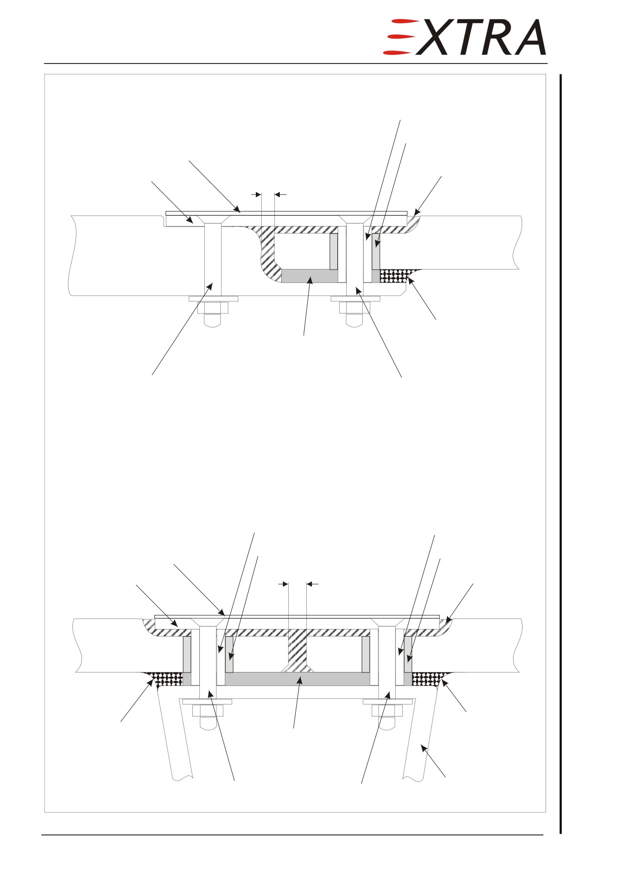
Sectional View Outer Windshield Attachment
Aluminum bushing
Rubber bushing
Outer frame cover
Outer frame
PR1829B
~2,5 mm
Fuselage
Windshield
structure
frame
Ottoseal S72
Silicone gasket seal
Outer frame attachment bolt
Windshield attachment bolt
Sectional View Middle Strut Windshield Attachment
Aluminum bushing
Aluminum bushing
Outer frame cover
Rubber bushing
Rubber bushing
Outer frame
PR1829B
~3 mm
Windshield
Windshield
Ottoseal S72
Ottoseal S72
Silicone gasket seal
Middle strut
Windshield attachment bolt
Figure 56-1
Windshield Installation
Page 6 56
Page Date:9. August 2013
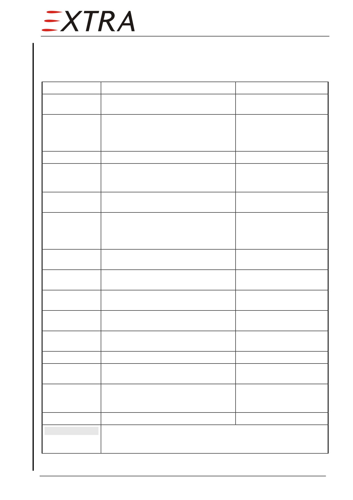
Installation
The new windshield is delivered without holes for bolt attachments. The holes
must be drilled to ensure matching the hole pattern of the structure and outer
frame. Refer to Figure 56-1.
Detail Steps/Work Items
Key Items
1
Place the windshield on the Silicone gasket
seal on the fuselage structure frame.
2
Adjust windshield position to receive
(~2,5 mm gap windshield to
minimum possible deviations from given
fuselage structure frame and
clearance.
~3 mm gap windshield to
windshield)
3
Place the outer frame on the windshields.
4
Prefix the windshield and the outer frame to
this position. Place shims to the gaps. Use
tape to fix the outer frame to the windshield.
5
Select 5 or 6 positions for pre-attachment of
the windshield.
6
Predrill 4 mm holes from both sides of the
Refer to Steps 1 and 2 of
windshield on selected positions. Drill with
Figure 56-2
reduced rotational speed. Plexiglass shall
not melt. Use a plexiglass-drill.
7
Pre-attach the windshield using 5 or 6
M4 bolts.
8
Predrill 4 mm holes on the remaining
Refer to Steps 1 and 2 of
attachment points.
Figure 56-2
9
Remove pre-attaching bolts and remove
outer frame and windshield.
10
Place the windshield on a cushioned surface
Drill in two phases. Refer to
and drill the remaining final 12 mm holes.
Step 3 of Figure 56-2
11
Add a 45° 1 mm chamfer on both sides of
Refer to Step 4 of Figure 56-2
each bore hole.
12
Install aluminum and rubber bushings.
13
Place the windshield to the fuselage
structure frame.
14
Adjust windshield as before and place the
outer frame on the windshield to check if
holes match.
15
Remove outer frame.
Note
Surfaces are difficult to clean from PR1829B.
Apply tape to windshield and structure parts where PR1829B shall not
adhere.
Page Date:9. August 2013
56 Page 7
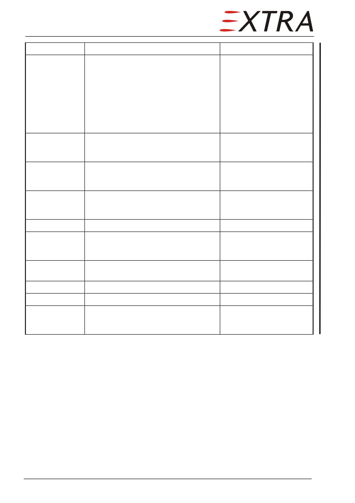
Detail Steps/Work Items
Key Items
16
Apply PR1829B to the windshield in the
Refer to PR1829B data and
area of outer frame. Outer frame shall
safety sheet especially for
slightly swim on the PR1829B before
curing time and conditions.
fastening the bolts.
Work in several phases when applying
PR1829B to avoid drying before attachment
of outer frame. Begin in the area of middle
strut. Then work towards the sides. Refer to
Figure 56-3.
17
Place the outer frame on the windshield.
Bend the outer frame to allow application of
PR1829B in later phases.
18
Install the attachment bolts in the area where
PR1829B is applied and tighten nuts to 3
thru 3.5 Nm (26 thru 31 in.lbs).
19
Remove projecting PR1829B after complete
Clean with isopropyl alcohol
installation of outer frame.
as long PR1829B is not yet
hardened.
20
Connect electrical wiring
21
Apply Ottoseal S72 to the gap between
Refer to Ottoseal S72 data
inner side of windshield and fuselage
and safety sheet especially for
structure frame/middle strut.
curing time and conditions.
22
Apply 1 layer 92110 glass fiber to build new
Refer to Chapter 51
outer frame cover.
23
Apply paint.
Refer to Chapter 51
24
Install glarshield and main panels.
Refer to Chapter 31
25
Install windshield middle strut paneling, LH
Refer to Chapter 25
and RH armrest paneling, upper side
paneling and front ceiling paneling.
Page 8 56
Page Date: 9. August 2013
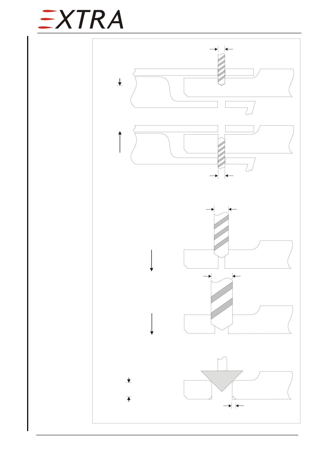
ø 4 mm
Outer frame
Step 1
Fuselage
Windshield
structure
frame
Outer frame
Fuselage
Windshield
Step 2
structure
frame
ø 4 mm
ø 8 mm
Step 3
Windshield
phase 1
ø 12 mm
Windshield
phase 2
Step 4
45°
Windshield
1 mm
Figure 56-2
Drilling Plexiglass
Page Date:
56 Page 9
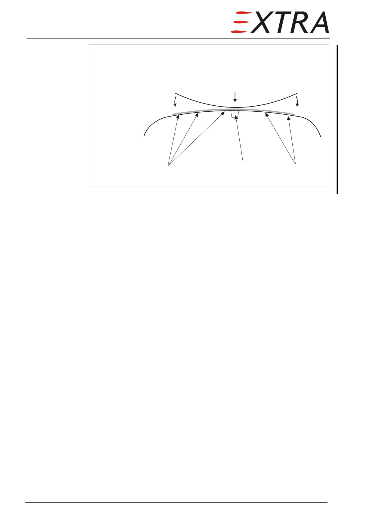
Sectional drawing
Outer frame
Aircraft contour
PR1829B application phases
Middle strut
PR1829B
Figure 56-3
Work in Phases
Page 10 56
Page Date:9. August 2013
56-20-00
CABIN
56-20-10
Cabin Windows
Description
The cabin windows feature double panes for redundancy in case of structural
failure of the outer pane. The outer pane is carrying the pressurization loads
during normal operation and consist of stretched acrylic material. The inner
pane is consisting of cast acrylic material and does not carry any load in normal
operation. The room between the two panes is connected to the pressure vessel
by a small orifice during normal pressurization. In case of structural failure of
the outer pane the inner pane takes the pressurization loads and the orifice
limits the leakage.
The middle windows on both sides are integrated in either the normal door on
the left side or into the emergency exit panel on the right side. Structurally they
are identical to the fixed windows.
All 6 cabin windows are contoured to match the fuselage shape individually.
To adjust the windows relative to the aircraft contour, spacers
(GFK or
equivalent) are used (refer to Figure 56-4).
If the attachment bolts are to be covered by paint, an optional cover consisting
of one layer 92110 glass fabric can be installed.
Removal
Refer to Figure 56-4.
Detail Steps/Work Items
Key Items
1
Remove respective paneling.
Refer to Chapter 25 or 52
2
Remove window attachment nuts.
3
Release frame from Ottoseal S72 using a
cutter knife.
4
Remove frame.
5
Peel off cover (if installed).
6
Remove window attachment bolts.
7
Release window from Ottoseal S72 using a
cutter knife.
8
Remove window.
9
Remove residual Ottoseal S72 sealant.
Replace damaged spacers
10
Remove aluminum and rubber bushings
Replace damaged bushings.
from old window for later transfer to the
new window.
Page Date:
56 Page 11
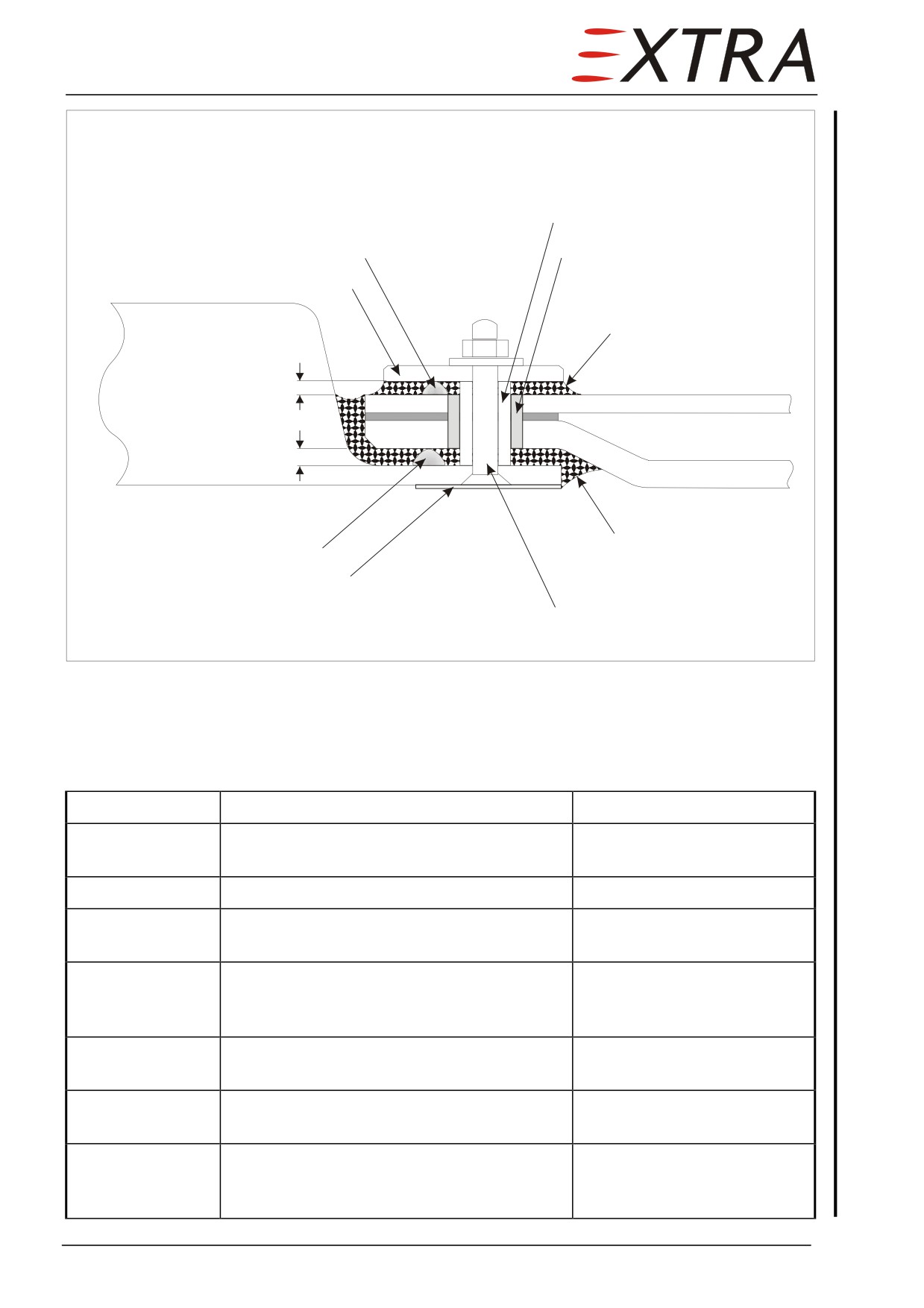
Sectional View Window Attachment
Aluminum bushing
Spacer
Rubber bushing
Frame
Ottoseal S72
Fuselage
1-3 mm
structure
Window
1-3 mm
Ottoseal S72
Spacer
Cover
Window attachment bolt
Figure 56-4
Window Installation
Installation
Refer to Figure 56-4.
Detail Steps/Work Items
Key Items
1
Install aluminum and rubber bushings to the
new window.
2
Place the window to the fuselage structure.
3
Adjust window position to match the
existing hole pattern.
4
Check if the outer window contour follows
Minimum spacer thickness:
the fuselage shape. Change spacers if
1 mm
necessary.
5
Apply Ottoseal S72 to the fuselage structure
Refer to Ottoseal S72 data
frame as outlined on Figure 56-4.
and safety sheet.
6
Place the window to the fuselage structure
and adjust window as before.
7
Place spacers on the windshield in the area
Minimum spacer thickness:
of frame. Spacer thickness shall match the
1 mm
vertical extension of aluminum bushings.
Page 12 56
Page Date: 9. August 2013