Extra 500. Maintenance Manual (2012) - page 13
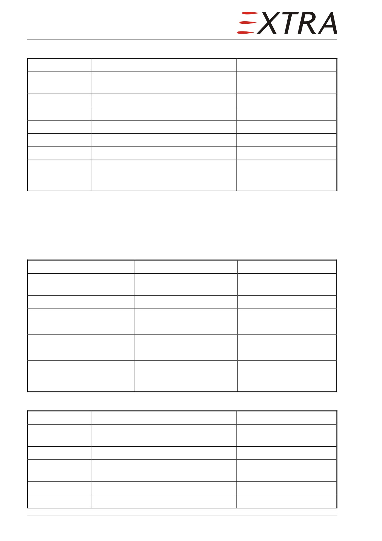
Removal/Installation
Detail Steps/Work Items
Key Items
1
Ensure BATT switch is OFF and no external
power connected.
2
Remove RH and LH IFD
Refer to Chapter 31
3
Disconnect (red) static pressure hose
4
Remove altimeter
3 screws
5
Disconnect electrical connector
6
Install in reverse sequence of removal
7
Perform Pitot/static check
According to FAR 43,
Appendix E and AC 43.13-
1B CHG1 (or later) § 12-59
34-10-02
Airspeed Indicator (2” type)
Troubleshooting
Complaint
Possible Cause
Remedy
Pointer does not indicate
Leak in instrument case, in
Check for leak and seal
properly
Pitot or static lines
Pointer of instrument oscillates
Defective mechanism
Replace instrument
Instrument reads high
Pointer not on zero
Replace instrument
Leaking static system
Find leak and correct
Instrument reads low
Pointer not on zero
Replace instrument
Leaking Pitot system
Find leak and correct
Airspeed changes as aircraft is
Water in pitot line
Remove line from all
banked
instruments and blow out line
from cockpit to Pitot head
Removal/Installation
Detail Steps/Work Items
Key Items
1
Ensure BATT switch is OFF and no external
power connected.
2
Remove RH and LH IFD
Refer to Chapter 31
3
Disconnect (red) static pressure hose and
(white) Pitot hoses
4
Remove airspeed indicator.
4 screws
5
Disconnect electrical connector.
Page 8 34
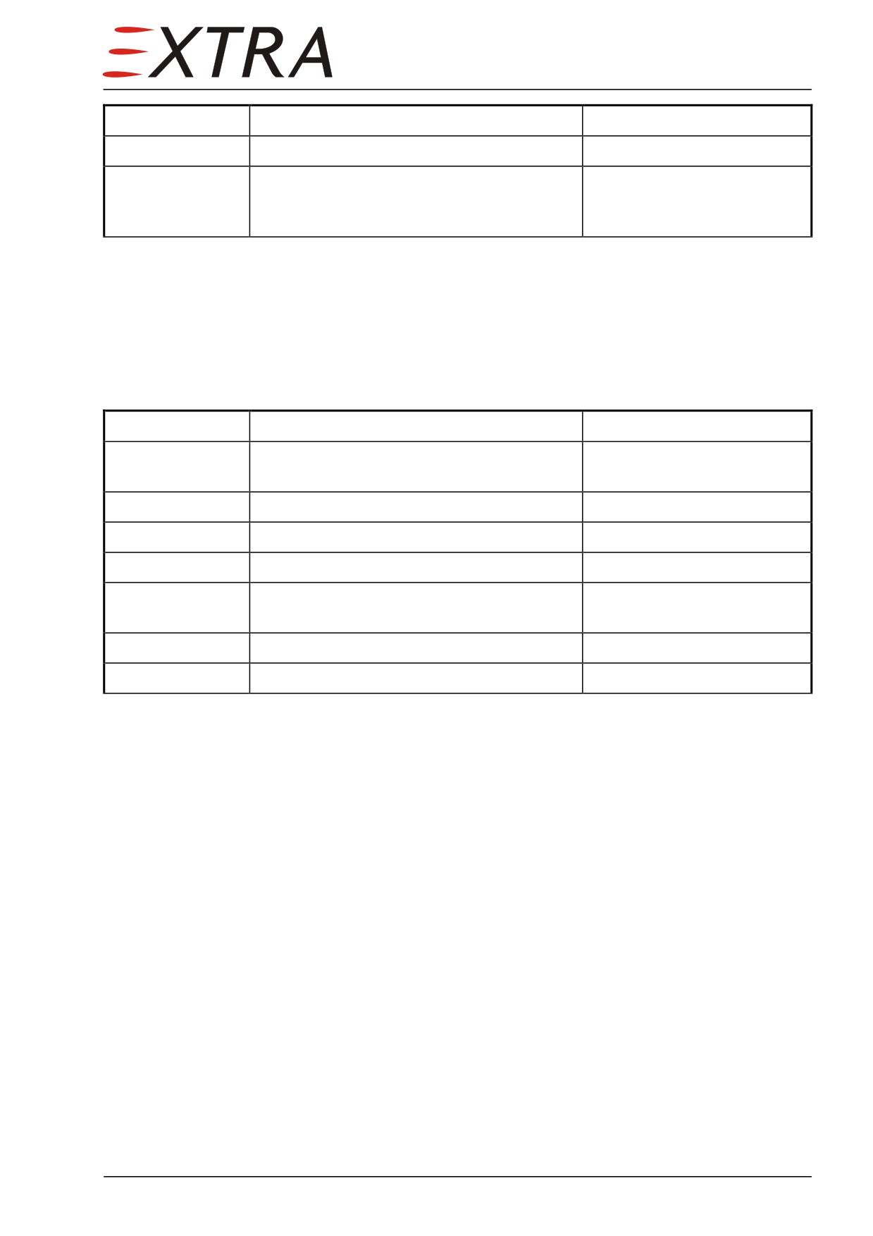
Detail Steps/Work Items
Key Items
6
Install in reverse sequence of removal.
7
Perform Pitot/static check
According to FAR 43,
Appendix E and AC 43.13-
1B CHG1 (or later) § 12-59
34-10-11
Pitot Head
Removal/Installation (LH/RH Side)
Refer to Figure 34-2.
Detail Steps/Work Items
Key Items
1
Ensure BATT switch is OFF and no external
power connected.
2
Remove outer wing access panel.
Refer to Chapter 51-00-01
3
Disconnect plug from sensor heat element.
4
Disconnect Pitot pressure line nut.
5
Remove 4 Phillips screws from Pitot tube
shaft at bracket.
6
Remove Pitot tube from bracket downwards.
7
Install in reverse sequence of removal.
34 Page 9
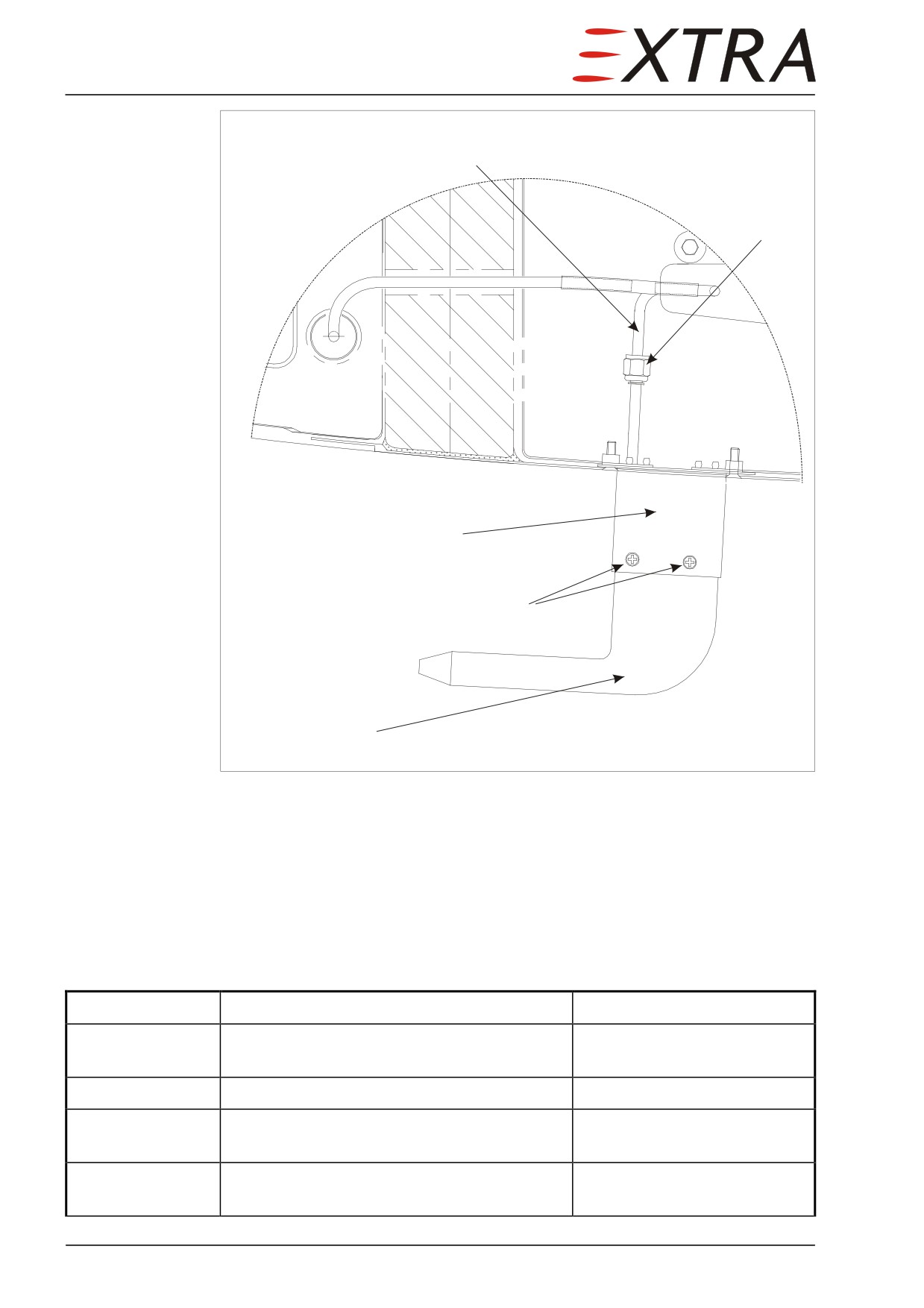
Pitot line
Nut
Bracket
Attachment screws
Pitot head
Figure 34-2
Pitot Head
34-10-12
Static Port
Removal (LH/RH Side)
Refer to Figure 34-3.
Detail Steps/Work Items
Key Items
1
Ensure BATT switch is OFF and no external
power connected.
2
Remove tail cone access panel
Refer to Chapter 51-00-01
3
Disconnect 2 static pressure hoses from
static port at LH/RH fuselage
4
Cut tie-wrap and wiring to heat element on
both sides of splice.
Page 10 34
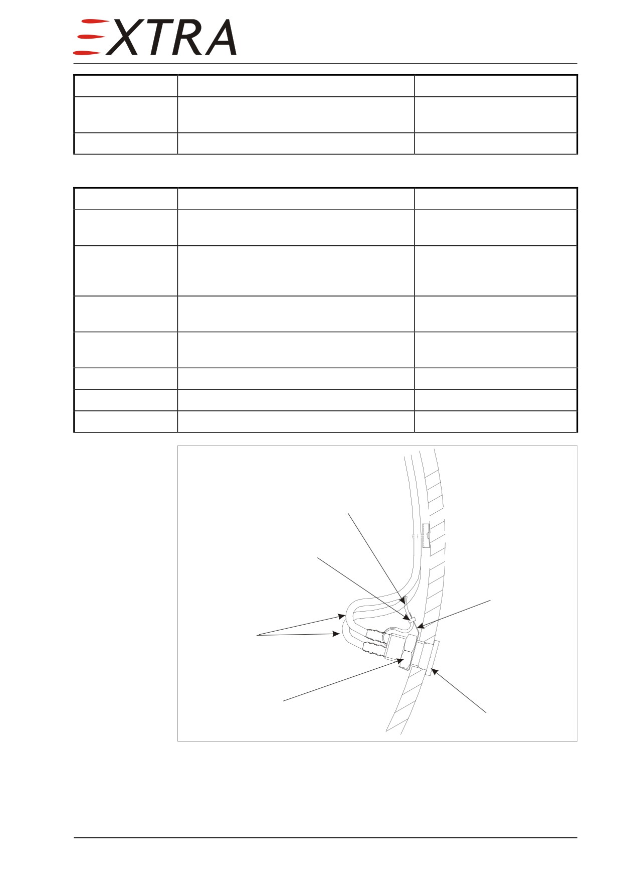
Detail Steps/Work Items
Key Items
5
Remove static port fastening nut and strain
relief.
6
Remove static port
Sensor is fitted with silicon
Installation (LH/RH Side)
Detail Steps/Work Items
Key Items
1
Ensure BATT switch is OFF and no external
power connected.
2
Install static port.
Apply silicon between
outside part of sensor and
fuselage
3
Install strain relief and static port fastening
Secure sensor fastening nut
nut
with Loctite 243.
4
Re-establish splice at wiring to heat
element.
5
Fasten wiring with tie-wrap.
6
Connect 2 static pressure hoses to static port
red upper, green lower
7
Install tail cone access panel
Refer to Chapter 51-00-01
Wiring
Tie wrap
Strain relief
Static hoses
Nut
Static port
Figure 34-3
Static Port
34 Page 11
34-10-13
Stall Warning Sensor
Removal/Installation (LH/RH Side)
Detail Steps/Work Items
Key Items
1
Ensure BATT switch is OFF and no external
power connected.
2
Remove LH wing nose access panel.
Refer to Chapter 51-00-01
3
Disconnect electrical connector from sensor.
4
Remove 4 bolts and nuts at sensor mounting
plate.
5
Remove sensor.
6
Install in reverse sequence of removal
Page 12 34
34-20-00
ATTITUDE AND DIRECTION
34-20-01
Attitude Indicator
Removal/Installation
Detail Steps/Work Items
Key Items
1
Remove RH and LH IFD
Refer to Chapter 31
2
Disconnect electrical connector.
3
Remove attitude indicator.
4 screws
4
Install in reverse sequence of removal.
34-20-02
Magnetic Compass
Removal/Installation
Detail Steps/Work Items
Key Items
1
Remove compass
2 screws
2
Disconnect electrical connector.
3
Install in reverse sequence of removal.
4
Make compass swing, if new unit is
installed.
5
Replace deviation card if necessary.
Bulb Replacement
Detail Steps/Work Items
Key Items
1
Ensure BATT switch is OFF and no external
power connected.
2
Lift cap on upper front surface.
3
Remove bulb.
4
Insert new bulb.
24 VDC
5
Refit cap.
Compass Swing
Refer to the Compensation Instructions of
Airpath Instrument Company
(LOAP 40). It is advisable to perform this compass swing simultaneously with
the IFD Magnetometer Calibration outlined in Chapter 31-60-01.
Page Date:
34 Page 13
34-40-00
INDEPENDENT POSITIONING DETERMINING
Description
The EXTRA 500 can be equipped with the following optional equipment:
• TAS (Traffic Avoidance System)
• TWX (Lightning detection system)
Troubleshooting
Complaint
Possible Cause
Remedy
TAS shows aircraft on the
Antenna cables of upper
Swap antenna cables
wrong side (left or right)
antenna swapped
TAS shows aircraft on the
Antenna cables of lower
Swap antenna cables
wrong side (front or aft)
antenna swapped
34-40-01
TAS Processor
The TAS processor is installed on the back of the aft baggage compartment
paneling.
Removal/Installation
Detail Steps/Work Items
Key Items
1
Ensure BATT switch is OFF and no external
power connected.
2
Remove aft baggage compartment paneling.
Refer to Chapter 25-00-01
3
Disconnect electrical connectors and
antenna cables from TAS processor.
4
Unscrew the locking screws of the TAS
processor mounting tray.
5
Slide the TAS processor out of the tray.
6
Install in reverse sequence of removal.
Observe the following hint
Make sure all antenna cables are connected to both antennas and TAS
CAUTION
processor before applying power to the processor. Failing to do so may
damage the processor.
Page 14 34
34-40-02
TWX Processor
The TWX processor is installed beneath the armrest of the second seat row, LH
seat.
Removal/Installation
Detail Steps/Work Items
Key Items
1
Ensure BATT switch is OFF and no external
power connected.
2
Remove LH front passenger seat.
Refer to Chapter 25-20-11
3
Remove LH side armrest paneling.
Refer to Chapter 25-20-21
4
Disconnect electrical connectors and
antenna cable from TWX processor
5
Remove TWX processor from tray
6
Install in reverse sequence of removal.
34 Page 15
34-50-00
DEPENDENT POSITIONING DETERMINING
Description
The EXTRA 500 has the following equipment installed:
• Transponder
In addition the following optional equipment may be installed:
• DME (Distance Measuring Equipment)
34-50-01
Transponder
The transponder is installed in the tail cone compartment.
Removal/Installation
Detail Steps/Work Items
Key Items
1
Ensure BATT switch is OFF and no external
power connected.
2
Remove the tailcone access panel
Refer to Chapter 51-00-01
3
Disconnect electrical connectors and
antenna cables
4
Remove transponder from its tray
2 screws
5
Install in reverse sequence of removal.
34-50-02
DME Processor
The DME processor is installed in the tail cone compartment
Removal/Installation
Detail Steps/Work Items
Key Items
1
Ensure BATT switch is OFF and no external
power connected.
2
Remove the tailcone access panel
Refer to Chapter 51-00-01
3
Disconnect electrical connectors and
antenna cables
4
Remove DME processor from its tray
2 screws
5
Install in reverse sequence of removal.
Page 16 34

34-50-03
DME Indicator
The DME indicator is installed on the instrument panel on the left lower edge.
Removal/Installation
Detail Steps/Work Items
Key Items
1
Ensure BATT switch is OFF and no external
power connected.
2
Disconnect electrical connector
Accessible from the bottom
3
Remove DME indicator
4 screws
4
Install in reverse sequence of removal.
34 Page 17
Chapter 51
Standard Practices and Structures
General
51 Page 1
Table of Contents
51-00-00
GENERAL
5
51-00-01
Access Panel Identification
.............................................................................. 5
Figure 51-1, Sheet 1Access Panel Identification
6
Figure 51-1, Sheet 2Access Panel Identification
7
Figure 51-1, Sheet 3Access Panel Identification
8
51-10-00
INVESTIGATION............................................................................................ 9
51-10-01
Damage Classification
...................................................................................... 9
51-10-02
Repair Criteria and Limits
.............................................................................. 9
51-10-02
Repair Criteria and Limits
10
51-30-00
MATERIALS
11
51-30-01
Composite Parts
11
Epoxy System
11
Glass Fibre Fabrics
11
Carbon Fibre Fabrics
12
Carbon Fibre Rovings
12
UD Carbon Fibre Tape
12
Core Material
12
Filler Material for Resin
14
Coating
14
51-30-02
Metal Components
15
Round Seamless Steel Tubing
15
Steel Sheet Metal
16
Coating
16
51-30-03
Aluminium Components
17
Aluminium Sheet Metal
17
Tubings
17
Coating
18
51-30-04
Titanium Components
18
Titanium Sheet Metal
18
51-30-05
Various Components
19
Sealant
19
Silicon Adhesive
19
Adhesive
20
Corrosion Preventive Compound
20
Sealing Material for Lightning Protection
20
Release Agent
20
Foam Rubber
21
Page 2 51
Page Date:
51-60-00
CONTROL SURFACE BALANCING
.........................................................22
51-60-01
Weighing and Determination of Control Surface Moments
......................22
Figure 51-2
Balancing Mandrels
..........................................................................................22
Procedure...........................................................................................................23
Figure 51-3
Control Surface Balancing
................................................................................24
Figure 51-4
Permissible Weights and Moments
...................................................................25
51-70-00
REPAIRS
.........................................................................................................26
51-70-01
Repair of Reinforced Glass and Carbon Fibre Components
......................26
51-70-02
Repair of Sandwich Material
.........................................................................28
Figure 51-5
Minor Surface Damage
.....................................................................................28
Figure 51-6
Curing Cycle Resin L 20 / SL
............................................................................29
Figure 51-7
Damage of Complete Sandwich
........................................................................30
51-70-03
Repair of Laminates
........................................................................................32
Minor Damage
32
Figure 51-8
Repair of Minor Damage
..................................................................................33
Large Damage
...................................................................................................33
51-70-04
Repair of Spars and Elements of the Pressure Cabin
..................................35
Structural elements of the pressure cabin..........................................................35
Spars of Wing and Empennage
.........................................................................35
51-70-05
Structural Repair of Steel Components
........................................................35
51-70-06
Painting of Composite Parts
...........................................................................36
51-70-07
Aluminium and Steel Components Refinishing
37
Degreasing.........................................................................................................37
Paint Removal
...................................................................................................37
Repainting
.........................................................................................................38
Page Date:
51 Page 3
51-00-00
GENERAL
51-00-01
Access Panel Identification
Refer to Figure 1 for identification of access panels.
Generally all access panels
(and fairings) are screwed on the respective
structure or surface. However for the access to the oil filler and the external
power receptacle hatches are used featuring a hinge and a latching mechanism.
The LH wing nose access panel carries the stall sensor. So refer to Chapter 34-
10-13 for removal.
To get access to the passenger compartment floor access panels the carpet has
to be removed.
To get access to the central horizontal stabilizer access panel the fin tip has to
be removed (refer to Chapter 55-30-01).
51 Page 5
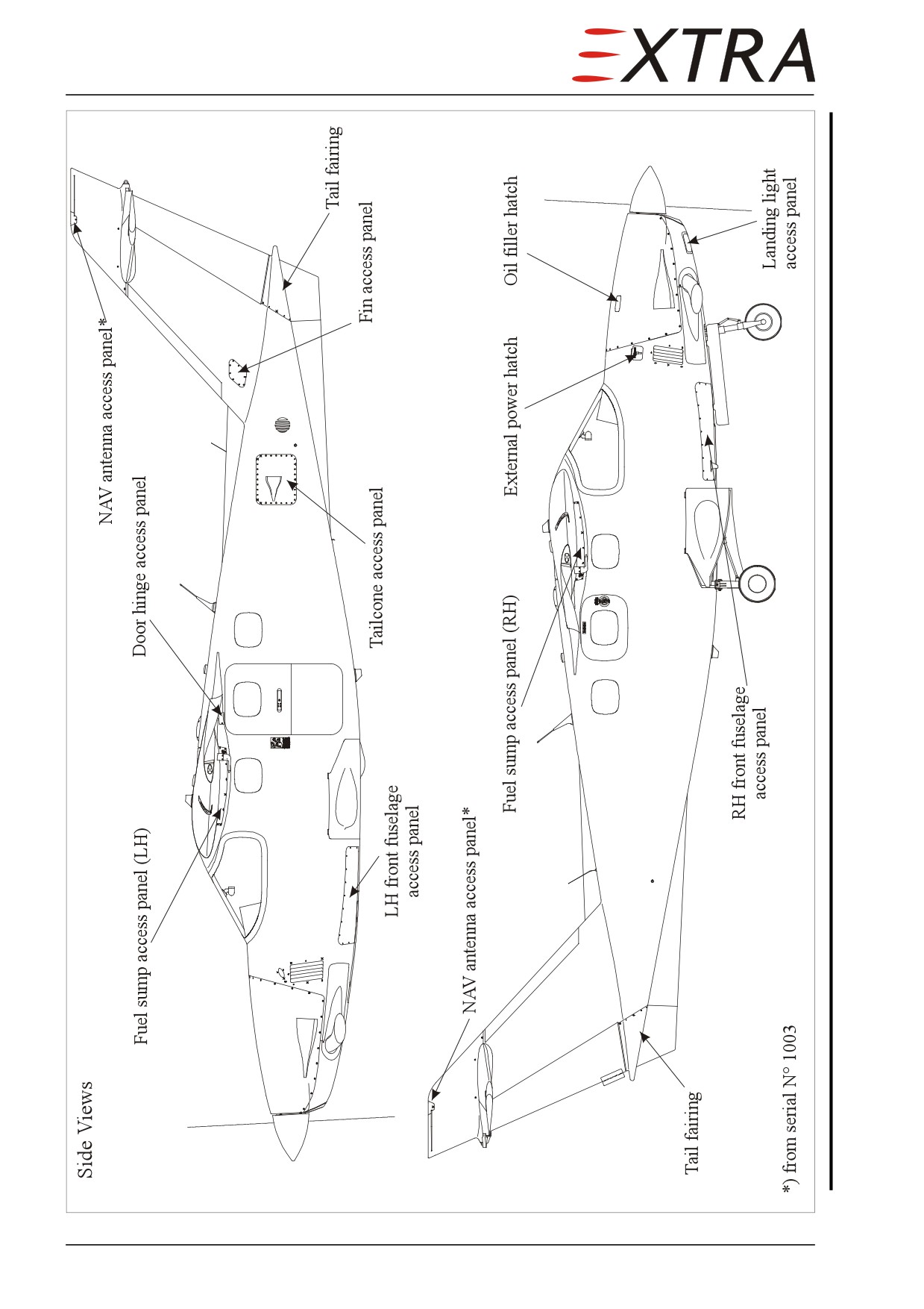
Figure 51-1, Sheet 1
Access Panel Identification
Page 6 51
Page Date:
11. July 2012
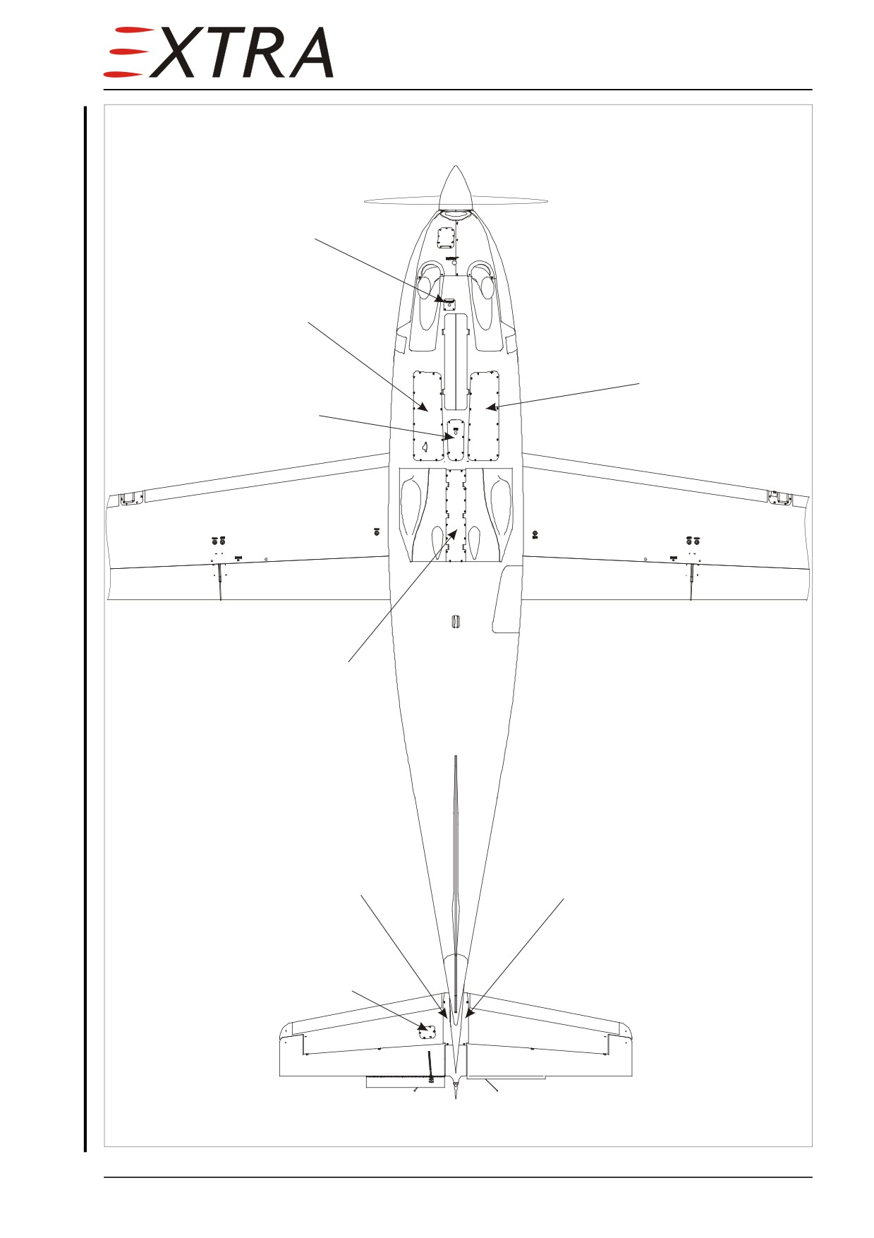
Bottom View
Fuel filter access panel
RH front fuselage
access panel
LH front fuselage
access panel
Forward keel beam
access panel
Aft keel beam
access panel
RH gap fairing
LH gap fairing
Pitch trim
access panel
Figure 51-1, Sheet 2
Access Panel Identification
Page Date:
11. July 2012
51 Page 7
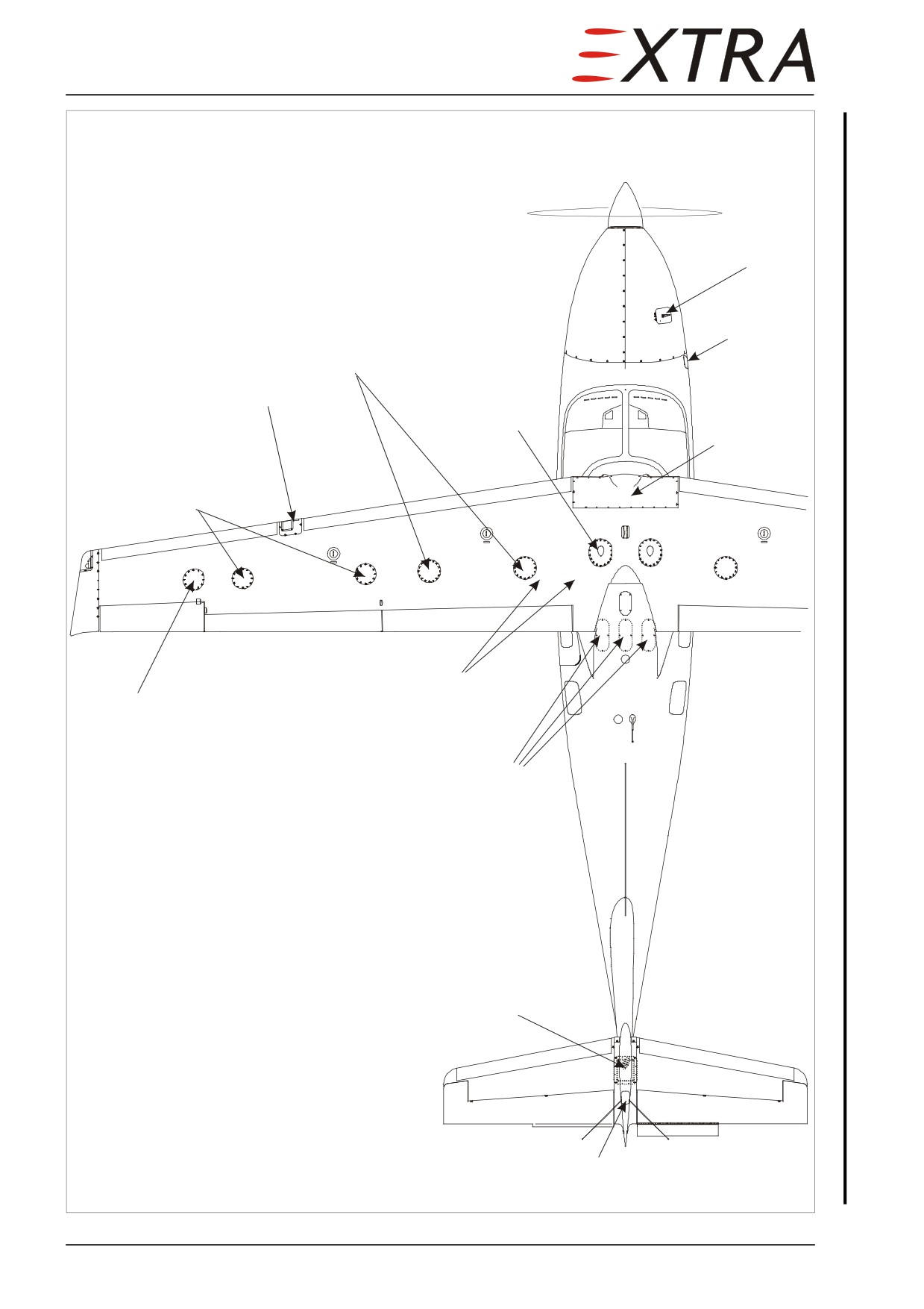
Top View
Oil filler hatch
Inner and outer
External power
fuel main compartment
hatch
access panels
Wing nose
access panel
Avionic bay
access panel
Wing center
fairing
Inner and outer
fuel auxiliary compartment
access panels
Right wing
symmetrically
Inspection doors
Outer wing
access panel
Passenger compartment floor
access panels (LH, middle, RH)
Central horizontal stabilizer
access panel
NAV antenna access panel
from serial N° 1003
Figure 51-1, Sheet 3
Access Panel Identification
Page 8 51
Page Date:
11. July 2012
51-10-00
INVESTIGATION
51-10-01
Damage Classification
All damage of composite parts must first be classified by qualified
WARNING
personnel. In case of doubt regarding the classification of damage, if a
clear definition of the extent of damage is not possible, or if a repair of
damage despite the consideration of the valid manufacturer
documentation is doubtful, contact EXTRA.
Only the Damages Classes 2, 3 and 4 may be repaired by qualified
WARNING
personnel. In case of Damage Class 1 EXTRA has to be contacted.
Following to the Luftfahrt Bundesamt (Federal German Aviation Authority)
four damage classes are defined:
Damage Class 1:
Large scale destruction requires a partial reconstruction of the component or
large scale repair. Each destruction over 300 mm diameter and each damage of
a spar or the pressure cabin is a “large scale destruction”. EXTRA has to be
contacted prior to repair.
Damage Class 2:
Damage to primary structures and to secondary structures to the following
extent: Holes and fractures extending through a sandwich component and a
scale under 300 mm diameter.
Damage Class 3:
Damage to primary structures and to secondary structures to the following
extent: Small holes or fractures in the external covering layers, if not
accompanied by damage to supporting layers or internal covering layers.
Damage Class 4:
Erosion, scratches or nicks not accompanied by fractures or break-ups. Damage
to fairings belong to this class.
Page Date:9. August 2013
51 Page 9
51-10-02Repair Criteria and Limits
IMPORTANT
Any damage of composite parts must first be classified prior to repair.
Refer to Subject 51-10-01 Damage Classification.
IMPORTANT
Only the Damages Classes 2, 3 and 4 may be repaired by qualified
personnel. In case of Damage Class 1 EXTRA has to be contacted.
The decision whether to repair or replace a major unit of structure will be
influenced by factors such as time and labor available, and by comparison of
labor costs with the price of replacement assemblies. Past experiences indicate
that replacement, in many cases, is less expensive than major repair. Certainly,
when the aircraft must be restored to its airworthy condition within limited
time, replacement is preferable.
Page 10 51
Page Date:

51-30-00
MATERIALS
This Section describes metallic and non-metallic materials used in repairing the
EXTRA 500 and gives the sources of supply (manufacturers and suppliers).
IMPORTANT
Only approved materials have to be used for repair.
Materials not listed here are generally used for parts, which are not intended for
repair. Contact EXTRA for advice.
Observe the data and safety sheets when working with auxiliary materials such
as sealants, adhesives, solvents, agents and the like. However, if not stated
otherwise, aircraft parts must not be heated to more than 80 °C (176 °F) for
example in curing processes.
51-30-01
Composite Parts
Epoxy System
Manufacturer: Momentive
Varzinerstr. 49,
D-47138 Duisburg, Germany
Supplier:
Brenntag GmbH
Stinnes Platz 1,
D-45472 Mühlheim, Germany
Resin:
Epikote L20 / Rütapox L20
Hardener:
Epikure Curing Agent 960 / Rütapox SL
Ratio of comp.: 100 parts L20 / 34 parts SL (weight ratio)
Glass Fibre Fabrics
Manufacturer: P-D Interglas Technologie GmbH
Benzstraße 14,
D-89155 Erbach, Germany
Style
WLB-No.*
US-style
Weave
Weight
Interglas
LN 9169
Patterns
g/m2
90070
8.4505.60
1610
plain
80
92110
8.4548.60
none
2/2 twill
163
92125
8.4551.60
none
2/2 twill
280
92140
8.4554.60
none
2/2 twill
390
Page Date:
51 Page 11

Carbon Fibre Fabrics
Manufacturer: C. Cramer GmbH & Co. KG
Division ECC
Weberstr. 21,
D-48619 Heek-Nienborg, Germany
Style
WLB-No.*
US-style
Weave
Weight
ECC/CCC
DIN 65147
Patterns
g/m2
447
8.3507.80
None
plain
160
452
8.3520.80
None
2/2 twill
204
459
-
None
2/2 twill
220
*WLB: Werkstoff Leistungsblatt, according to German standard DIN-WL
Carbon Fibre Rovings
Manufacturer: Toho Tenax Europe GmbH
Kasinostr. 19-21
D-42103 Wuppertal
Type:
TENAX HTS5631 1600tex f24000 t 0
(WLB: 8.3614.1)
UD Carbon Fibre Tape
Manufacturer: J.H.vom Baur Sohn GmbH & Co. KG
Marktstraße 34
D-42396 Wuppertal, Germany
Type:
CF UD tape 30 mm & 50 mm
according material spec. Doc. N° EA-05803.1 & .2
Core Material
PVC (Polyvinylchloride) Foam
Manufacturer: Airex AG
Industrie Nord 26
CH-5643 Sins, Switzerland
Supplier:
Gaugler & Lutz OHG
Habsburger Str. 12
D-73432 Aalen-Ebnat, Germany
Type:
Airex C 71.55
Page 12 51
Page Date:
PMI (Polymethacrylimide) Foam
Manufacturer: Evonik Röhm GmbH
Kirschenallee
D-64293 Darmstadt, Germany
Supplier:
Gaugler & Lutz OHG
Habsburger Str. 12
D-73432 Aalen-Ebnat, Germany
Type:
Rohacell 51 A
(WLB*: 5.1460.1)
*WLB: Werkstoff Leistungsblatt, according to German standard DIN-WL
Honeycomb
Manufacturer: Euro Composites S.A.
B.P.95, Zone Industrielle
L-6401 Echternach / Luxembourg
or :
Manufacturer: Schütz GmbH & Co. KGaA:
Schützstr. 21
D-56242 Selters, Germany
Honeycomb
Density
Manufacturer
Specification
Tolerance
Cormaster C1-4,8-29 OX
+15%/-0%
Schütz
EA-03512.02
ECA-R-4.8-29
+13%/-0%
Euro Composites
EA-03512.02
ECA-I-R-4.8-29
+16%/-0%
Euro Composites
EA-03512.02
Cormaster C1-4,8-48 OX
±10%
Schütz
WLB5.3653.1*
ECA-R-4.8-48
±10%
Euro Composites
WLB5.3653.1*
ECA-I-R-4.8-48
±16%
Euro Composites
ECSS 704
Cormaster C1-3.2-48
±10%
Schütz
WLB5.3650.4*
ECA-I-3.2-48
±16%
Euro Composites
ECSS 704
*WLB: Werkstoff Leistungsblatt, according to German standard DIN-WL
Plywood
Manufacturer: For example: Mahogany Oy, Finnland
Supplier:
For example: La Boisserolle
71960 Prissé-Lès-Mâcon, France
Type:
Aircraft grade Birch produced to German Lloyd GL-I & -II,
t = 2 mm, 6 mm, 8 mm (WLB*: 6.1013.0)
Okoume t = 4 mm, t = 6 mm**
*WLB: Werkstoff Leistungsblatt, according to German standard DIN-WL
**Aircraft Grade acc. to French Standard
51 Page 13
Filler Material for Resin
Manufacturer:
STW Schwarzwälder Textilwerke
Heinrich Kaukmann GmbH
Aue 3
D-77773 Schenkenzell, Germany
Supplier:
same
Type:
Cotton flakes FB1/035
Manufacturer:
Malayan Adhesives & Chemicals Sdn Bhd
No. 9 Jalan Utas 15/7,
40200 Shah Alam Selangor Darul Ehsan, Malaysia
Supplier:
Brenntag GmbH
Stinnes-Platz 1
D-45472 Mühlheim, Germany
Type:
Microballoons BJO - 0930
Coating
Manufacturer:
BASF Coatings GmbH
Glasuritstr. 1,
D-48165 Münster/Hiltrup, Germany
Supplier:
Wessels & Müller AG
Pagenstecherstraße 121,
D-49090 Osnabrück, Germany
Type:
22
Glasurit HS-2K-Decklack
929-91/93/94
Glasurit HS Decklackhärter
352-50/91/216
Glasurit Einstellzusatz
55
Glasurit Zweischicht-Decklack
Metallic/Uni/Perleffekt
352-50/91/216
Glasurit Einstellzusatz
90
Glasurit Zweischicht-Decklack
Metallic/Uni/Perleffekt
93-E3
Glasurit Einstellzusatz
923-155
Glasurit MS-Klarlack
929-91/93/94
Glasurit HS Decklackhärter
352-50/91/216
Glasurit Einstellzusatz
285-100 VOC
Glasurit Rapidfüller VOC, weiß
929-55/56
Glasurit HS Füllerhärter
352-91
Glasurit Einstellzusatz
1006-26
Glasurit UP Spritzfüller, grau
948-22
Glasurit Härter
839-53
Glasurit UP-Schnellspachtel
Page 14 51
Page Date:
948-36
Glasurit Härterpaste
293-10
Glasurit Einstellzusatz
934-0
Glasurit 1K-Kunststoffhaftprimer
Manufacturer: MOTIP DUPLI GmbH
Kurt-Vogelsang-Straße 6
D-74855 Haßmersheim, Germany
Supplier:
Wessels & Müller AG
Pagenstecherstraße 121,
D-49090 Osnabrück, Germany
Type:
presto Leichtspachtel prestolith easy
Fire Protective Coating
Manufacturer: PPG Aerospace, PRC-DeSoto
Supplier:
Röder Präzision GmbH
Am Flugplatz
D-63329 Egelsbach, Germany
Type:
Fire protective coating N56582/T508
with clear coat:
Clearcoat 4232-0303
Hardener N39/1327
Reducer N39/3091
Manufacturer: Rudolf Hensel GmbH
Lauenburger Landstraße 11
D-21039 Börnsen, Germany
Supplier:
same
Type:
Fire protective coating Hensotherm 410KS
with clear coat (see Manufacturer above):
923-335 Glasurit HS-Multi-Klarlack VOC (clear coat)
929-31/33/34 Glasurit HS Decklackhärter (hardener)
51-30-02
Metal Components
Round Seamless Steel Tubing
Manufacturer: MHP Mannesmann Hoesch Präzisrohr GmbH
Postfach 1713,
D-59061 Hamm, Germany
Supplier:
Heggemann Autosport GmbH
Zeppelinring 1 - 6,
D-33142 Büren, Germany
Page Date:9. August 2013
51 Page 15
Type:
WLB* 1.7734.4
various diameters and wall dimensions
(for example: engine mount)
Manufacturer: Pacific Tube Company
5710 Smithway Street
Los Angeles, California 90040, USA
Supplier:
Wicks Aircraft Supply, Co.
410 Pine Street
Highland, Illinois 62249, USA
Type:
AISI 4130 N (MIL-T-6736)
various diameters and wall dimensions
(for example: support structure inside cabin)
Steel Sheet Metal
Manufacturer:
BÖHLER Edelstahl GmbH
München, Germany
Supplier:
BÖHLER Edelstahl GmbH
Hansa Allee 321
D-40549 Düsseldorf, Germany
Type:
according to WLB* 1.7734.4, various dimensions
Manufacturer:
Cold Metal Products, Inc.
2301 So. Holt Road
Indianapolis, In. 46241, USA
Supplier:
Wicks Aircraft Supply, Co.
410 Pine Street
Highland, Illinois 62249, USA
Type:
AISI 4130 N (MIL-S-18729)
various dimensions
Coating
Manufacturer:
BASF Coatings GmbH
Glasuritstr. 1,
D-48165 Münster/Hiltrup, Germany
Supplier:
Wessels & Müller AG
Pagenstecherstraße 121,
D-49090 Osnabrück, Germany
Type:
801-72 VOC Glasurit Grundfüller EP VOC, grau
965-60
Glasurit Härter EP
352-91/216
Glasurit Einstellzusatz
22
Glasurit HS-2K-Decklack
929-91/93/94 Glasurit HS Decklackhärter
352-50/91/216 Glasurit Einstellzusatz
*WLB: Werkstoff Leistungsblatt, according to German standard DIN-WL
Page 16 51
Page Date:
51-30-03
Aluminium Components
Aluminium Sheet Metal
Manufacturer: Kaiser Aluminium & Chem. Corp.
Spokane, Washington
Supplier:
Westdeutscher Metallhandel
Friedrich W. Hermann GmbH
Manderscheidtstr. 76-78,
Postfach 104245
45141 Essen
Type:
WLB* 3.1364 T3 (2024 T3)
various dimensions
WLB* 3.3214 T6 (6061 T6)
various dimensions
*WLB: Werkstoff Leistungsblatt, according to German standard DIN-WL
Manufacturer:
various
Supplier:
Westdeutscher Metallhandel
Friedrich W. Hermann GmbH
Manderscheidtstr. 76-78,
Postfach 104245
45141 Essen
Type:
AlMg3hh (EN-AW-5754 H24)
various dimensions (also band)
Tubings
Manufacturer:
Aluminium AG
CH-5737 Menziken, Swiss
Supplier:
Westdeutscher Metallhandel
Friedrich W. Hermann GmbH
Manderscheidtstr. 76-78,
Postfach 104245
45141 Essen
Type:
WLB* 3.1354 T3
various dimensions
WLB* 3.3214 T4
various dimensions
*WLB: Werkstoff Leistungsblatt, according to German standard DIN-WL
Manufacturer: various
Supplier:
Wicks Aircraft Supply, Co.
410 Pine Street
Highland, Illinois 62249, USA
Type:
5052-0
various dimensions
51 Page 17
2024 T3
various dimensions
Manufacturer:
various
Supplier:
Westdeutscher Metallhandel
Friedrich W. Hermann GmbH
Manderscheidtstr. 76-78,
Postfach 104245
45141 Essen
Type:
AlMgSi 0.5 F22 (EN-AW 6060 T6)
various dimensions
Coating
Manufacturer:
BASF Coatings GmbH
Glasuritstr. 1,
D-48165 Münster/Hiltrup, Germany
Supplier:
Wessels & Müller AG
Pagenstecherstraße 121,
D-49090 Osnabrück, Germany
Type:
283-150 VOC Glasurit Grundfüller EP VOC
352-228
Glasurit Zusatzlösung
352-50/91
Glasurit Einstellzusatz
22
Glasurit HS-2K-Decklack
929-91/93/94
Glasurit HS Decklackhärter
352-50/91/216 Glasurit Einstellzusatz
Manufacturer:
Parker & Anchem, Ambler, PA 19002
Supplier:
Aircraft Spruce
Chem. coating:
for aluminium hardware metal (brackets, pedestals etc.)
Type:
Alodine No. 1201 (MIL-C-5541)
Lacquer:
see above
51-30-04
Titanium Components
Titanium Sheet Metal
Manufacturer: Timet
United Kingdom
Supplier:
Tisto Titan und Sonderlegierungen GmbH
Dinnendahlstraße 31
40235 Düsseldorf, Germany
Type:
WLB* 3.7034.1 and 3.7024.1
(firewall, nose gear box, lightning protection tank filler caps)
*WLB: Werkstoff Leistungsblatt, according to German standard DIN-WL
Page 18 51
Page Date:
51-30-05
Various Components
Sealant
Manufacturer: Le Joint Français
Supplier:
Deutsche Hutchinson GmbH
Rudolf-Diesel-Str. 20B
65760 Eschborn, Germany
Type:
PR 148 AF Activator (for metal surfaces)
PR 1750 S
Integral tank sealant sprayable
PR 1750 A2
Integral tank sealant, bolt sealing
PR 1750 B2
Sealant (tank, pressure cabin, fittings etc.)
PR 1829 B
Window sealant
PR 812
Firewall sealant
Manufacturer: FLEET SUPPLIES, INC
215 Mahoning Avenue
Cleveland, OH 44113, USA
Supplier:
Aircraft Spruce and Speciality Co.
Type:
FUELUBE
Silicon Adhesive
Manufacturer:
Herrman Otto GmbH
Krankenhausstr. 14
D-83413 Fridolfing, Germany
Supplier:
same
Type:
Ottoseal S72
Manufacturer:
Dow Corning GmbH
Postfach 13 03 32
65201 Wiesbaden,Germany
Supplier:
Brammer GmbH
Daimlerstraße 51
76185 Karlsruhe, Germany
Type:
Dow Corning 732 white or clear (MIL-A-46106)
Manufacturer:
Wacker Chemie AG
Hannes-Seidel-Platz 4
81737 München, Germany
Supplier:
Wacker Chemie AG
Verkaufsbüro Stuttgart
Sophienstr. 41
70178 Stuttgart, Germany
Type:
Elastosil E14 (RTV 1)
51 Page 19
Manufacturer:
Momentive (formerly GE Silicones)
22 Corporate Woods Boulevard
Albany, NY 12211, USA
Supplier:
diverse
Type:
RTV 159 (high temperature & high strength Silicone)
Adhesive
Manufacturer:
Henkel AG & Co. KGaA
Henkelstr. 67
D-40589 Düsseldorf, Germany
Supplier:
Wessels & Müller AG
Pagenstecherstraße 121,
D-49090 Osnabrück, Germany
Type:
Loctite 243
Threadlocker
Loctite 401
Instant adhesive
Loctite 406
Instant adhesive
Loctite 577
Thread sealing
Loctite 601
Small gaps retainer
Corrosion Preventive Compound
Manufacturer: LEAR CHEMICAL RESEARCH
P.O. Box 1040, Mississauga
L4Y 3W3 Ontario, Canada
Supplier:
Global Aviation & Piper Parts GmbH
Flughafen Kassel, D-34379 Calden
Type:
ACF-50
Sealing Material for Lightning Protection
Manufacturer: Nycote Laboratoires
12750 Raymer Street
North Hollywood, CA 91605
Supplier:
Aero Consultants
PO Box 35, Grabenstrasse 8
CH-8606 Nänikon/Uster, Switzerland
Type:
Nycote 7-11 (MIL-S-4383)
Release Agent
Manufacturer: CIBA Speciality Chemicals Inc.
CH-4002 Basel, Switzerland
Supplier:
Schurg GmbH
Industriestr. 12
D-34537 Bad Wildungen, Germany
Type:
QV 5110
Page 20 51
Page Date:
Foam Rubber
Manufacturer: JPR Espace Industriel Nord
Rue André Durouchez
BP 1561
80015 Amiens cedex 02 - France
Supplier:
same
Type:
Silicone D563, colour grey, Ø 15 mm
Page Date:9. August 2013
51 Page 21
51-60-00
CONTROL SURFACE BALANCING
51-60-01
Weighing and Determination of
Control Surface Moments
Weighing and determination of control surface moments is necessary after
repairs or painting. All weighing of control surfaces is performed with surfaces
removed from aircraft. Weigh the control surfaces including mass balances and
brackets but without control rods.
The RH elevator weight includes the trim tab installed and provisionally held
in elevator surface plane by means of tape (see also Figure 51-3).
Copy Figure 51-4, enter the values (W, m, r) and check whether the surface
weights and moments are within the given tolerances. If they are not, contact
the EXTRA for advice.
For the determination of control surface moments follow the steps as described
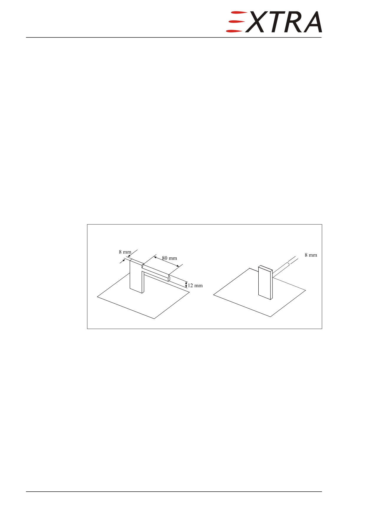
below and use two balancing mandrels like shown in the Figure 51-2:
A
B
(for outboard aileron hinge)
Ø
Figure 51-2
Balancing Mandrels
Page 22 51
Page Date:
Procedure
Detail Steps/Work Items
Key Items
1
Remove the control surface.
Refer to Chapter 27
2
Reinstall the bolts in the brackets where
Aileron inboard hinge
applicable.
Elevator outboard hinge
3
When weighing RH elevator fix trim tab
with tape.
4
Put the control surface on the balancing
Refer to Figure 51-3
mandrels (use a wire for the trim tab).
5
Level control surfaces and weigh by means
Refer to Figure 51-3
of a conventional spring balance (kg/g-
indication) at the given weighing points and
enter the weight (m) in figure 4.
6
Measure distance of hinge center line to
weighing point (r) and enter the value in
Figure 51-4.
7
Calculate the control surface moment (M) in
Figure 51-4.
IMPORTANT
If values exceed the given tolerances in Figure 51-4 contact EXTRA
before modifying of control surfaces.
8
If necessary modify control surface under
EXTRA’s guidance.
9
Reinstall the control surfaces.
Page Date:
51 Page 23