Extra 500. Maintenance Manual (2012) - page 12
32-30-22
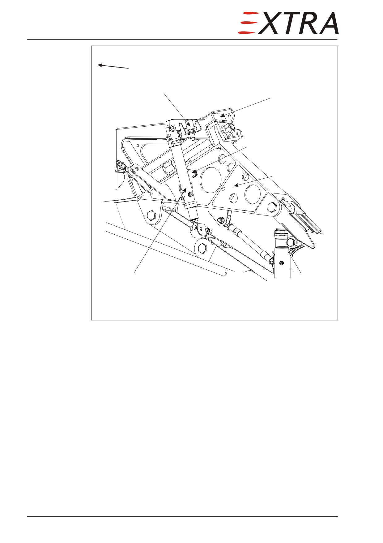
Upper Doors Actuator
Removal/Installation
Detail Steps/Work Items
Key Items
Landing gear extends and retracts under high pressure. Operation of
DANGER
the landing gear can cause death or injuries in its working area!
Before beginning any work in the landing gear working area, pull the
electric circuit breaker located on the left side panel and marked
GEAR-CTRL.
In case of intentional gear operation by switch or circuit breaker
handling make sure, that neither a person nor any object is located in
the upper landing gear doors travel area.
Hydraulic fluid can cause disease!
WARNING
Do not allow hydraulic fluid to come in contact with your skin.
Hydraulic fluid can damage paint and other material!
CAUTION
Clean up immediately spilt hydraulic fluid.
1
Remove the respective front fuselage access
Refer to Chapter 51-00-01
panel.
2
Remove the hydraulic lines from the fittings
Chapter 32-31-00
of the hydraulic actuator.
3
Install blind plugs to the disconnected lines
to avoid trapped air in the system.
4
Remove the bolt, the stop nut and the
washers between the rod end of the
hydraulic actuator and the torque tube.
5
Remove the cotter pin from the clevis pin
6
Remove the washer and clevis pin between
Hold the hydraulic actuator
the cylinder side of the hydraulic actuator
and the support
7
Remove the hydraulic actuator
8
Remove the bolts, the stop nuts and the
washers between the torque tube and the
cardan joint
9
Remove the torque tube
10
Remove the bolts, the stop nuts and the
Hold the cardan joint
washers between the cardan joint and the
shaft
11
Remove the cardan joint
12
Remove the bolts, the stop nut and the
Hold the push pull rod
washers from the push pull rod
13
Remove the push pull rod
Page 44 32
Page Date:
Detail Steps/Work Items
Key Items
14
Remove the bolt, the stop nut and the
washer from the lever
15
Pull off the lever from the shaft
16
Pull out the shaft of the bearing
17
Remove the collar bushing
18
Install in reverse sequence of removal
Use new stop nuts
19
Perform Bleeding procedure.
Refer to Subject 32-30-10
32-30-23
Lower Doors Actuator
Removal/Installation
Detail Steps/Work Items
Key Items
Landing gear extends and retracts under high pressure. Operation of
DANGER
the landing gear can cause death or injuries in its working area!
Before beginning any work in the landing gear working area, pull the
electric circuit breaker located on the left side panel and marked
GEAR-CTRL.
In case of intentional gear operation by switch or circuit breaker
handling make sure, that neither a person nor any object is located in
the upper landing gear doors travel area.
Hydraulic fluid can cause disease!
WARNING
Do not allow hydraulic fluid to come in contact with your skin.
Hydraulic fluid can damage paint and other material!
CAUTION
Clean up immediately spilt hydraulic fluid.
1
Remove the aft keel beam access panel.
Refer to Chapter 51-00-01
2
Remove the hydraulic lines from the fittings
Chapter 32-30-30
of the hydraulic actuator.
3
Install blind plugs to the disconnected lines
to avoid trapped air in the system.
3
Remove the cotter pins from the clevis pins
on the hydraulic actuator.
4
Remove the clevis pin between the rod end
of the hydraulic actuator and the actuator
lever.
5
Remove the clevis pin between the cylinder
Hold the hydraulic actuator
side of the hydraulic actuator and the
support.
32 Page 45
Detail Steps/Work Items
Key Items
6
Remove the hydraulic actuator
7
Remove the cotter pins from the clevis pins
on the hinge joints
8
Remove the clevis pins and the washers
from the hinge joints
9
Remove the hinge joints
10
Remove the bolts, the stop nuts and the
washers between the actuator lever and both
torque tubes
11
Pull out the torque tube LH of the actuator
Hold the actuator lever
lever and the bearing
12
Remove the actuator lever from the torque
Hold the torque tube
tube RH
13
Pull out the torque tube RH of the bearing
14
Remove the collar bushing from the keel
beams
15
Install in reverse sequence of removal
Use new stop nuts
16
Perform Bleeding procedure.
Refer to Subject 32-30-10
32-30-24
Nose Gear Actuator
Removal/Installation
Detail Steps/Work Items
Key Items
Landing gear extends and retracts under high pressure. Operation of
DANGER
the landing gear can cause death or injuries in its working area!
Before beginning any work in the landing gear working area, pull the
electric circuit breakers located on the left side panel and marked
GEAR-CTRL.
In case of intentional gear operation by switch or circuit breaker
handling make sure, that neither a person nor any object is located in
the upper landing gear doors travel area.
1
Lift the aircraft on jacks
Chapter 07-10-00
Hydraulic fluid can cause disease!
WARNING
Do not allow hydraulic fluid to come in contact with your skin.
Hydraulic fluid can damage paint and other material!
CAUTION
Clean up immediately spilt hydraulic fluid.
Page 46 32
Page Date:
Detail Steps/Work Items
Key Items
2
Remove the hydraulic lines from the fittings
Chapter 32-30-30
of the hydraulic actuator.
3
Install blind plugs to the disconnected lines
to avoid trapped air in the system.
4
Remove the bolt, the stop nut and the
washer from the rod end of the hydraulic
actuator.
5
Remove the bolt, the stop nut and the
Hold the hydraulic actuator
washer from the cylinder side of the
hydraulic actuator.
6
Remove the hydraulic actuator.
7
Measure the fully extended actuator length.
8
Install in reverse sequence of removal.
Use new stop nuts
9
Check actuator for length.
Set the fully extended length
to the previously measured
length.
10
Perform Bleeding procedure.
Refer to Subject 32-30-10
32-30-25
Nose Gear Gas Pressurized Springs
Removal/Installation
Detail Steps/Work Items
Key Items
Landing gear extends and retracts under high pressure. Operation of
DANGER
the landing gear can cause death or injuries in its working area!
Before beginning any work in the landing gear working area, pull the
electric circuit breaker located on the left side panel and marked
GEAR-CTRL.
In case of intentional gear operation by switch or circuit breaker
handling make sure, that neither a person nor any object is located in
the upper landing gear doors travel area.
1
Lift the aircraft on jacks
Chapter 07-10-00
Preload of the gas pressurized spring damages limbs!
WARNING
2
Remove cotter pin, washer and castle nut
Counteract spring forces at
from the connection between drag brace and
lower drag brace.
trunnion.
3
Remove the bolt (AN 6) from the drag brace
Slowly move down drag
sheathing at trunnion.
brace and thus release gas
spring.
32 Page 47
Detail Steps/Work Items
Key Items
4
Remove the cotter pin and the outside
washer from the clevis pin on the rod end of
the gas pressurized springs.
5
Remove the cotter pin, washer and castle nut
on the cylinder side of the gas pressurized
springs.
6
Remove the bolt of the gas pressurized
springs.
7
Remove the gas pressurized springs.
8
Install in reverse sequence of removal
Test Procedure
Detail Steps/Work Items
Key Items
1
Lift the aircraft on jacks
Chapter 07-10-00
NOTE
Landing gear must remain extended for testing.
Landing gear extends and retracts under high pressure. Operation of the
DANGER
landing gear can cause death or injuries in its working area! Make sure,
that neither a person nor any object is located in the landing gear travel
area.
2
Turn BATT switch OFF.
Ensure external power is not connected.
3
Pull circuit breaker GEAR-CTRL.
4
Attach a strap connecting both main gear legs.
5
Attach a strap on the nose-wheel axis.
6
Connect the nose-wheel strap with the main
Tensiometer: 100- 120 N,
gear strap using a tensiometer.
(1 N resolution and accuracy)
7
Pull the nose gear back while manually
With the ratchet of the strap
unlocking the drag brace. Set the nose gear at
(242 mm nose gear axle
20 degrees retracted.
travel; the upper part of the
drag brace should be
horizontal)
8
Pull the nose gear back by hand another
100mm and release slowly to the 20 degree
position.
9
Read the strap tension; depending on the
Refer to Minimum Tension
temperature, the tension should be at least as
Forces table
depicted in the table below.
10
If tensiometer reads lower than applicable
chart value:
a
With actuators and springs disconnected,
Page 48 32
Page Date:
Detail Steps/Work Items
Key Items
check trunnion bearing and drag brace
bearings for excessive friction.
b
Check for freedom of excessive friction or
jamming after connecting the locking strut to
the nose gear leg.
c
Replace both gas-pressurized springs if lack
of extension force is not caused by friction.
11
Release nose gear, ensure nose gear is locked,
remove straps and put aircraft back to normal.
Minimum Tension Forces
Temperature
Tension
Temperature
Tension
[°C]
[N]
[°F]
[lbs]
0
105
32
24
10
108
50
24
20
113
68
25
30
116
86
26
40
120
104
27
32-30-30
Hydraulic Lines
Description
The hydraulic devices are connected by aluminum tubes and PTFE hoses.
All actuators are generally connected by flexible PTFE hoses:
•
The main gear actuators and the nose gear actuators are connected by PTFE
hoses size 04.
•
The upper and lower door actuators of the main gear are connected by PTFE
hoses size 03.
The supply systems, the hydraulic power pack and the hydraulic control unit
are connected by aluminum tubes and PTFE hoses:
•
The connection from the hydraulic control unit to the respective main gear
actuator, up to the tee type or cross type fitting on the keel beam, is composed
of aluminum tube size 04.
•
The connection from the hydraulic control unit to the upper door actuators of
the main gear, up to the tee type fitting between the keel beams, is composed of
aluminum tube size 03.
•
The connection from the hydraulic control unit to the nose gear actuators, up to
the elbow fitting on the keel beam, is composed of PTFE hose size 04. From
32 Page 49
the elbow fitting to the tee type fitting in the nose gear compartment the
connection is composed of aluminum tube size 04.
• The connection from the hydraulic control unit to the lower door actuator of
the main gear is composed of PTFE hose size 03.
• The connection from the hydraulic control unit to the hydraulic power pack is
composed of PTFE hoses size 04.
The hydraulic system is separated in three circuits to actuate the respective
devices:
1 Extension/retraction of main gear and nose gear
2 Opening/closing of the lower main gear doors
3 Opening/closing of the upper main gear doors
32-30-40
Torque Link Rod and Track Rods
Removal/Installation
This procedure applies for all kind of rods used in the landing gear.
Detail Steps/Work Items
Key Items
1
Lift the aircraft on jacks
Chapter 07-10
Landing gear extends and retracts under high pressure. Operation of
DANGER
the landing gear can cause death or injuries in its working area!
Before beginning any work in the landing gear working area, pull the
electric circuit breaker located on the left side panel and marked
GEAR-CTRL.
In case of intentional gear operation by switch or circuit breaker
handling make sure, that neither a person nor any object is located in
the upper landing gear doors travel area.
False reassembled bolted connections can damage the gear struts and
CAUTION
doors.
Before removal of bolts and nuts, notice their position.
2
Remove the bolts, the stop nuts and the
washers connecting the respective rod to the
main gear strut assembly.
3
Install in reverse sequence of removal
Use new stop nuts
Page 50 32
Page Date:
32-30-50
Drive Mechanism Nose Doors
Removal/Installation
Detail Steps/Work Items
Key Items
Landing gear extends and retracts under high pressure. Operation of
DANGER
the landing gear can cause death or injuries in its working area!
Before beginning any work in the landing gear working area, pull the
electric circuit breaker located on the left side panel and marked
GEAR-CTRL.
In case of intentional gear operation by switch or circuit breaker
handling make sure, that neither a person nor any object is located in
the upper landing gear doors travel area.
False reassembled bolted connections can damage the gear struts and
CAUTION
doors.
Before removal of bolts and nuts, notice their position.
1
Remove the bolts, the stop nuts and the
Hold the push pull rod
washers from the push pull rods.
2
Remove the push-pull rods.
3
Remove bolts of telescope guide rod.
4
Remove telescope guide rod.
5
Remove bolt of nose gear door spring.
6
Remove nose gear door spring.
7
Install in reverse sequence of removal.
Use new stop nuts
32 Page 51
32-40-00
WHEELS AND BRAKES
Description
The nose gear and the main gear struts have single wheels carrying low-
pressure tube-type tires.
The nose wheel has a 5.00-5, ply. 6 tire with an inner tube. The nose wheel hub
has two aluminum alloy halves. Three bolts hold the halves together.
The main wheels, being similar constructed as the nose wheel, have 15x6.00-6
tube tires.
Each main wheel hub carries a hydraulically actuated single-disk brake on the
inside. The toe-brake pedals on the rudder pedals operate the brakes by the
hydraulic master cylinder. Hydraulic lines and hoses are routed from each
master cylinder to the wheel cylinder on each brake assembly. The brakes can
be actuated from either the pilot's or copilot's seat.
The parking brake valve system consists of a manually operated control
assembly located on the middle console and connected to the parking brake
valve. Applying pressure to the brake system by pressing the toe pedals and
pulling the parking brake control sets the parking brake. Pushing the parking
brake control forward releases the brakes.
Do not set the parking brake when brakes are overheated after heavy
CAUTION braking or when outside temperatures are unusually high. Trapped
hydraulic fluid may expand with heat and damage the system.
32-40-01
Main Wheels
Removal/Installation
Detail Steps/Work Items
Key Items
1
Lift the aircraft on jacks.
Chapter 07-10
Landing gear extends and retracts under high pressure. Operation of
DANGER
the landing gear can cause death or injuries in its working area!
Before beginning any work in the landing gear working area, pull the
electric circuit breakers located on the left side panel and marked
GEAR-CTRL.
In case of intentional gear operation by switch or circuit breaker
handling, make sure that neither a person nor any object is located in
the upper landing gear doors travel area.
The inflated tube tenses the wheel rim construction!
WARNING
Before working deflate the tire by the valve completely.
2
Remove the brake without disconnecting the
Refer to Subject 32-40-03
brake hose.
omitting steps 2 and 3
Page 52 32
Page Date:
Detail Steps/Work Items
Key Items
3
Remove the cotter pins from the hub nut.
4
Remove the hub nut.
5
Remove the rim from the main gear strut.
6
Remove the stop nuts and the washer from
the bolts.
7
Remove the bolts from both wheel halves
and the brake disk.
8
Remove both wheel halves from the tire.
9
For removing of the cup and cone bearing in
both wheel halves perform as described in
Cleveland Maintenance Manual.
10
Remove the tube from the tire.
11
Install in reverse sequence of removal.
Use new stop nuts
32-40-02
Nose Wheel
Removal/Installation
Detail Steps/Work Items
Key Items
1
Lift the aircraft on jacks.
Chapter 07-10-00
Landing gear extends and retracts under high pressure. Operation of
DANGER
the landing gear can cause death or injuries in its working area!
Before beginning any work in the landing gear working area, pull the
electric circuit breaker located on the left side panel and marked
GEAR-CTRL.
In case of intentional gear operation by switch or circuit breaker
handling, make sure that neither a person nor any object is located in
the upper landing gear doors travel area.
The inflated tube tenses the wheel rim construction!
WARNING
Before working deflate the tire by the valve completely.
2
Remove the cotter pin on one side of the
through bolt.
3
Remove the castle nut and the washer from
the through bolt.
4
Remove the through bolt from the rim nose
gear.
5
Remove the spacer sleeves from the rim.
Hold the rim
6
Remove the axle from the rim.
32 Page 53
Detail Steps/Work Items
Key Items
7
Remove the stop nuts and the washer from
the bolts.
8
Remove the bolts and the washer from both
wheel halves.
9
Remove both wheel halves from the tire.
10
For removing of the cup and cone bearing in
both wheel halves perform as in Cleveland
Maintenance Manual described.
11
Remove the tube from the tire.
12
Install in reverse sequence of removal.
Use new stop nuts
32-40-03
Brake
Removal/Installation
Detail Steps/Work Items
Key Items
1
Lift the aircraft on jacks.
Chapter 07-10-00
Landing gear extends and retracts under high pressure. Operation of
DANGER
the landing gear can cause death or injuries in its working area!
Before beginning any work in the landing gear working area, pull the
electric circuit breaker located on the left side panel and marked
GEAR-CTRL.
In case of intentional gear operation by switch or circuit breaker
handling, make sure that neither a person nor material is located in the
landing gear working area.
Brake fluid can cause disease!
WARNING
Do not allow brake fluid to come in contact with your skin.
Brake fluid can damage paint and other material!
CAUTION
Clean up immediately spilt brake fluid.
2
Disconnect the brake hose from the elbow
Catch the brake fluid. Put
fitting of the brake.
caps on the opened lines and
fittings
3
Install blind plug to the disconnected line to
avoid trapped air in the system.
4
Cut off the safety wire on the bolts.
5
Remove the bolts from the brake.
6
Remove the brake from the axle bar.
Fasten the brake at the main
gear strut with a tape to
protect the brake hose
Page 54 32
Page Date:
Detail Steps/Work Items
Key Items
7
Remove the cotter pins from the hub nut.
8
Remove the hub nut.
9
Remove the rim from the main gear strut.
10
Remove the stop nuts and the washer from
the bolts.
11
Remove the bolts from both wheel halves
and the brake disk.
12
Remove both wheel halves from the tire.
13
For removing of the cup and cone bearing in
both wheel halves perform as described in
Cleveland Maintenance Manual.
14
Remove the tube from the tire.
15
Install in reverse sequence of removal.
Use new stop nuts
16
Bleed the brake line.
32 Page 55
32-50-00
STEERING
Description
The EXTRA 500 has a controllable nose wheel. The steering arm of the
extended nose wheel is linked to the rudder pedals by springs and control
cables. The control cables are tightened by additional springs
(mounted
beneath the shelf) to prevent them from coming-off from the pulley.
Nose gear retraction automatically disengages the steering mechanism from the
nose wheel. The steering arm aligns the nose wheel for entry into the wheel
bay and, during flight, fixes it in the center nose of the guide block.
Nose wheel steering is accomplished through the use of the rudder pedals.
Pushing on one rudder pedal steers the aircraft to that side. The maximum nose
gear turning angle is 300 to either side while taxiing. During standstill the
rudder pedals control only the rudder.
Removal/Installation
Removal/Installation of the steering control cable is described in Chapter 27
Flight Controls.
Page 56 32
Page Date:
32-60-00
POSITION AND WARNING
Description
The LANDING GEAR switch is located on the L/H instrument panel and has the
positions UP and DN for retracting and extending the landing gear. It is
necessary first to pull out the selector switch handle prior to moving it up or
down. The switch is fitted with a small wheel for easy identification and
assisting in moving the switch in rough air.
The downlock information, for each wheel separately, is given by three green
lights located near the LANDING GEAR switch. The red GEAR WARN light on
the annunciator panel indicates that the landing gear is not completely retracted
or extended.
The entire electric control processes signals from limit switches, indicating the
completion of actions of the respective hydraulic circuits, and from the landing
gear switches.
In emergency case it can be deactivated by pulling the GEAR-CTRL circuit
breaker. The directional valves are spring-loaded and will automatically switch
in the GEAR DOWN position once electrical power is lost. As long as the
LANDING GEAR switch is in DN-position the gear downlock indication will still
be operative, however the prescribed reclosing of the upper main doors will not
happen.
A warning horn is furnished on the EXTRA 500 in combination with the red
GEAR WARN light on the annunciator panel to caution the pilot against landing
with the landing gear being retracted. A respective acoustic warning signal is
heard on the headphones simultaneously.
Firstly, the warning light and horn will be activated in case of the landing gear
being still retracted, while engine torque is below 35 % for descent or landing
approach and with wing flaps being in 0°- or 15°- position. If landing is not
intended pressing the gear warning mute button located on the left side of the
power lever will switch off the horn and the warning light.
Secondly, if engine torque is below 35 % for normal landing approach and
wing flaps are in landing position (30°), the warning light will illuminate and
the warning horn will sound independently from the gear warning mute button
until the landing gear will be completely extended. The function of the red
GEAR WARN light and the aural warning can be tested switching the
NIGHT/DAY switch on the left side panel to the TEST position.
Separate position switches monitor the landing gear struts and doors:
•
Extending and retracting of each main gear strut and the nose gear strut
•
Opened and closed position of the upper and lower main gear doors
Generally micro switches are used.
During ground operation, a ground safety switch prevents accidental gear
retraction by disconnecting the main valve from DC, regardless of LANDING
GEAR switch position. It is located on the nose landing gear just above the
torque link.
32 Page 57
fwd
Main gear retracted switch
Main gear attachment frame
Main gear extended switch
Undercarriage leg
Torque link rod
Figure 32-9
Main Gear Switches (LH)
32-60-01
Main Gear Extended Switches
The main gear extended switches are located on the undercarriage leg of the
LH and RH main gear as shown on Figure 32-9.
32-60-02
Main Gear Retracted Switches
The main gear retracted switches are located at the main gear attachment frame
next to the upper torque link attachment as shown on Figure 32-9.
When the left and right gear retracted switches are reached, the upper door
valve is powered to close the upper doors. The closing of the upper doors then
causes the two upper door closed switches (see below) to power the lower door
valve, which closes the lower doors.
Page 58 32
Page Date:
The closed upper doors are held in place not only by hydraulic power, but also
by the lower doors overlapping them. Therefore the upper doors need to be
closed first.
32-60-03
Upper Main Door Opened Switch
The upper door opened switches are operated by the rod of the hydraulic
actuator upper door.
When the upper main doors are fully opened, the two upper main door opened
switches will power the main valve which will retract the main gear strut.
32-60-04
Upper Main Door Closed Switch
The upper main door closed switches are operated by the rod of the hydraulic
actuator upper door.
32-60-05
Lower Main Door Closed Switch
The lower main door closed switch is operated by the actuator lower door,
opening circuit when the lower doors are closed completely.
After all doors are closed the door closed switches upper/lower door cut off the
power from the gear in-transition information. In case of wheel bay doors
being opened during flight due to reduced system pressure, the gear in-
transition information will warn the pilot from abnormal system state by the
red gear warning light in the instrument panel. At the same time the hydraulic
pump will be activated to reclose the door accordingly.
32-60-06
Ground Safety Switch
The function is realized by two switches. They are installed on the nose gear
just above the torque link (refer to Figure 32-5).
32-60-07
Nose Gear Extended Switch
The nose gear extended switch is mounted to the nose gear drag brace and is
operated when the drag brace is in the over-centered position. It controls the
green nose gear downlock light in the instrument panel (refer to Figure 32-5).
32 Page 59
32-60-08
Nose Gear Retracted Switch
The nose gear retracted switch is located in the front part of the nose gear
wheel well (refer to Figure 32-6) and operated by a bracket attached to the
trunnion. It is used for the red GEAR WARN light to signal if the nose gear is
fully retracted or not.
32-60-09
Operation and Indication
The operation and indication assembly has the following components:
Indication lights - Gear extended (three greens)
LANDING GEAR switch
Annunciator light - GEAR WARN
Annunciator light - HYDRAULIC PUMP
Page 60 32
Page Date:
Chapter 33
Lights
33 Page 1
Table of Contents
33-00-00
GENERAL
3
Description
3
33-10-00
FLIGHT COMPARTMENT
4
Description
4
33-20-00
PASSENGER COMPARTMENT
5
Description
5
33-40-00
EXTERIOR
6
Description
6
33-40-01
Wing Tip Navigation/Strobe Lights
6
Removal/Installation
6
33-40-02
Tail Navigation/Strobe Light
7
Removal/Installation
7
33-40-03
Strobe Light Power Supply (Wing)
7
Removal/Installation
7
33-40-04
Strobe Light Power Supply (Tail)
8
Removal/Installation
8
33-40-05
Landing Light
9
Removal/Installation
9
33-40-06
Recognition Light
9
Removal/Installation
9
Page 2 33
33-00-00
GENERAL
Description
The EXTRA 500 is equipped with lights in the flight compartment for proper
instrument and label reading in reduced ambient light conditions. The
passenger compartment is also lighted for passenger comfort, but those lights
can be switched off by the pilot at any time for safety reasons. External lighting
is provided to ‘see and to be seen’.
33 Page 3
33-10-00
FLIGHT COMPARTMENT
Description
The cockpit is lighted with the following lights:
• Instrument lights, including switches backlighting
• Lights in the glareshield
• Two dome lights in the ceiling
• Two map lights in the ceiling
• And for emergencies a flash light behind the co-pilot seat
The instrument lights, switches backlighting, annunciator lights, lights in the
glare shield and keypad/IFD backlighting are all dimmable by their respective
potentiometer on the instrument panel.
Dimming is activated by the NIGHT/DAY switch in the left side panel. The
instrument lights and switches backlighting
(INSTR), glareshield lights
(GLARE), and the map lights (MAP) have their individual switches on the left
side panel.
The dome light switch is located adjacent to the dome light.
Page 4 33
33-20-00
PASSENGER COMPARTMENT
Description
The passenger compartment lighting consists of:
• Ambient lighting on the central air-conditioning channel
• A reading light for each passenger in the side walls
These can be switched on and off by the passenger individually, but the CABIN
LIGHT switch in the left side panel has priority to switch all passenger lighting
off.
33 Page 5
33-40-00
EXTERIOR
Description
Exterior lights consist of:
• Strobe lights at the wing tips and the fin tip (also refer to Whelen Anti-
Collision Light Systems Installation and Service Manual, LOAP 43)
• Navigation lights at the wing tips
• Landing light in the lower RH cowling
• Two recognition lights, also used for taxiing, installed in the wing leading edge
on both sides.
• Ice light (described in Chapter 30-80-01)
Each light (-group) has its own switch and circuit breaker in the left side panel
(CABIN/CABIN-LT, RECO/RECO-LT NAV/NAV-LT, LDG/LDG-LT).
The strobe light power supply for the wing mounted strobes is installed in the
wing nose, just right of the forward-middle wing compartment. The tail power
supply is installed in the vertical tail tip.
33-40-01
Wing Tip Navigation/Strobe Lights
Removal/Installation
Detail Steps/Work Items
Key Items
High voltage can cause injuries!
WARNING
Let power supply stand for 5-10 minutes after disconnecting from power
source to allow power to bleed off capacitors before beginning any work
on the strobe light systems. Even after 5-10 minutes, care should be
taken when handling components as electrical shock can result.
1
Pull the STROBE-LT circuit breaker.
Let power supply stand for 5-
10 minutes.
2
Also pull the NAV-LT circuit breaker.
3
Remove the Phillips screws from the wing
Hold the wing tip glass cover
tip glass cover.
4
Remove the wing tip glass cover
5
Remove the lens retainer mounting Phillips
screw and retainer.
6
Remove counter-sunk screws and base
assembly from wingtip.
7
Disconnect electrical connectors.
Page 6 33
Detail Steps/Work Items
Key Items
8
Install in reverse sequence of removal
33-40-02
Tail Navigation/Strobe Light
Removal/Installation
Detail Steps/Work Items
Key Items
High voltage can cause injuries!
WARNING
Let power supply stand for 5-10 minutes after disconnecting from power
source to allow power to bleed off capacitors before beginning any work
on the strobe light systems. Even after 5-10 minutes, care should be
taken when handling components as electrical shock can result.
1
Pull the STROBE-LT circuit breaker.
Let power supply stand for 5-
10 minutes.
2
Also pull the NAV-LT circuit breaker.
3
Remove the retainer mask Phillips screws.
Remove the unit.
4
Disconnect electrical connector.
5
Install in reverse sequence of removal
33-40-03
Strobe Light Power Supply (Wing)
Removal/Installation
Detail Steps/Work Items
Key Items
High voltage can cause injuries!
WARNING
Let power supply stand for 5-10 minutes after disconnecting from power
source to allow power to bleed off capacitors before beginning any work
on the strobe light systems. Even after 5-10 minutes, care should be
taken when handling components as electrical shock can result.
1
Pull the STROBE-LT circuit breaker.
Let power supply stand for 5-
10 minutes.
2
Remove the wing center fairing.
Refer to Chapter 51-00-01
3
Disconnect the electrical wiring of the
power supply
4
Disconnect the ground bonding lead
33 Page 7
Detail Steps/Work Items
Key Items
5
Remove the Phillips screws from the power
supply unit
6
Pull out the power supply unit and remove
from the attaching plate
Reverse polarity of the input power, for just an instant, will
CAUTION
permanently damage power supply. This damage is sometimes not
immediately apparent, but will cause failure later on. Black lead is
negative.
7
Install in reverse sequence of removal
33-40-04
Strobe Light Power Supply (Tail)
Removal/Installation
Detail Steps/Work Items
Key Items
High voltage can cause injuries!
WARNING
Let power supply stand for 5-10 minutes after disconnecting from power
source to allow power to bleed off capacitors before beginning any work
on the strobe light systems. Even after 5-10 minutes, care should be
taken when handling components as electrical shock can result.
1
Pull the STROBE-LT circuit breaker.
Let power supply stand for 5-
10 minutes.
2
Remove fin tip.
Refer to Charter 55-30-01
3
Disconnect the ground bonding lead
4
Remove the Phillips screws from the power
supply unit
5
Pull out the power supply unit and remove
from the attaching plate
Reverse polarity of the input power, for just an instant, will
CAUTION
permanently damage power supply. This damage is sometimes not
immediately apparent, but will cause failure later on. Black lead is
negative.
6
Install in reverse sequence of removal
Page 8 33
33-40-05
Landing Light
Removal/Installation
Detail Steps/Work Items
Key Items
1
Pull LDG-LT circuit breaker.
2
Remove upper cowlings.
Refer to Chapter 71-10-01/02
3
Remove external landing light glass.
8 screws
4
Remove landing light cover.
2 screws
5
Disconnect electrical connection.
6
Remove lamp with igniter.
Retainer clip
7
Remove reflector with frame.
2 screws
8
Install in reverse sequence of removal
33-40-06
Recognition Light
Removal/Installation
Detail Steps/Work Items
Key Items
1
Pull RECO-LT circuit breaker.
2
Remove respective wing nose access panel.
Refer to Chapter 51-00-01
3
Remove baffle with recognition light.
3 screws
4
Disconnect electrical connector.
5
Remove recognition light from baffle.
2 screws
6
Install in reverse sequence of removal
33 Page 9
Chapter 34
Navigation
34 Page 1
Table of Contents
34-00-00
GENERAL
5
Pitot/Static Pressure Systems.............................................................................. 5
Avionics
.............................................................................................................. 5
Figure 34-1
Pitot Static System Schematic
............................................................................. 6
34-10-00
FLIGHT ENVIRONMENTAL DATA
........................................................... 7
34-10-01
Altimeter (2” type)
............................................................................................ 7
Troubleshooting
.................................................................................................. 7
Removal/Installation
........................................................................................... 8
34-10-02
Airspeed Indicator (2” type)
............................................................................ 8
Troubleshooting
.................................................................................................. 8
Removal/Installation
........................................................................................... 8
34-10-11
Pitot Head
.......................................................................................................... 9
Removal/Installation (LH/RH Side)
................................................................... 9
Figure 34-2
Pitot Head
10
34-10-12
Static Port
10
Removal (LH/RH Side)
10
Installation (LH/RH Side)
11
Figure 34-3
Static Port
11
34-10-13
Stall Warning Sensor
12
Removal/Installation (LH/RH Side)
12
34-20-00
ATTITUDE AND DIRECTION
13
34-20-01
Attitude Indicator
13
Removal/Installation
13
34-20-02
Magnetic Compass
13
Removal/Installation
13
Bulb Replacement
13
Compass Swing
13
34-40-00
INDEPENDENT POSITIONING DETERMINING
14
Description
14
Troubleshooting
14
34-40-01
TAS Processor
14
Removal/Installation
14
34-40-02
TWX Processor
15
Removal/Installation
15
34-50-00
DEPENDENT POSITIONING DETERMINING
16
Description
16
Page 2 34
Page Date:
34-50-01
Transponder
....................................................................................................16
Removal/Installation
.........................................................................................16
34-50-02
DME Processor
................................................................................................16
Removal/Installation
.........................................................................................16
34-50-03
DME Indicator
17
Removal/Installation
.........................................................................................17
34 Page 3
34-00-00
GENERAL
Pitot/Static Pressure Systems
Providing pitot and static pressure for the pilot's and copilot's instruments two
independent systems are installed (refer to Figure 34-1). Each system consists
of a heated pitot head located at about 3/4 of the wing span, the tubing
including a drain and the respective instruments. The heated static ports are
located on both sides of the rear fuselage. The two toggle-type drains are
located at the fuselage underside, between the keel beams. They are accessible
by the forward keel beam access panel.
When the pitot heat switches are placed in the ON position, the heating
elements in the pitot heads and the static port for the autopilot are electrically
energized to maintain proper operation of the systems during icing conditions.
Normally, the heating elements can only be activated when airborne. On
ground the system is deactivated by the squat switch, which detects aircraft
being on ground.
For testing on ground, pitot heat switches provide a TEST position (momentary
ON).
In testing mode, do not operate pitot & static heat longer than 10 seconds
CAUTION
to prevent overheating of the heating elements.
Care should be taken when an operational check of the heated pitot heads
WARNING
is being performed on the ground. The units become very hot.
An additional static system is installed in the tail cone for the autopilot. The
static port is located on the lower aft part of the vertical stabilizer. The static
line is routed from there to the bottom of the tail cone compartment. There, on
the lowest point of the system a plugged hose serves as a drain. Remove the
plug for draining. The static line is further routed via T-fitting to the autopilot
pressure transducer.
Avionics
The EXTRA 500 is equipped with Avidyne Entegra equipment. Please refer to
Chapter 31. This chapter will deal with other avionics apart from Back-up
altimeter and airspeed indicator:
•
Back-up attitude indicator
•
Magnetic compass
•
XPDR
•
DME (option)
•
TAS (option)
•
TWX (option)
IMPORTANT
Avionics service and repair work requires special skills, tools and test
equipment. In case of instrument failure or malfunction contact manu-
facturer or authorized service center.
Page Date:
34 Page 5
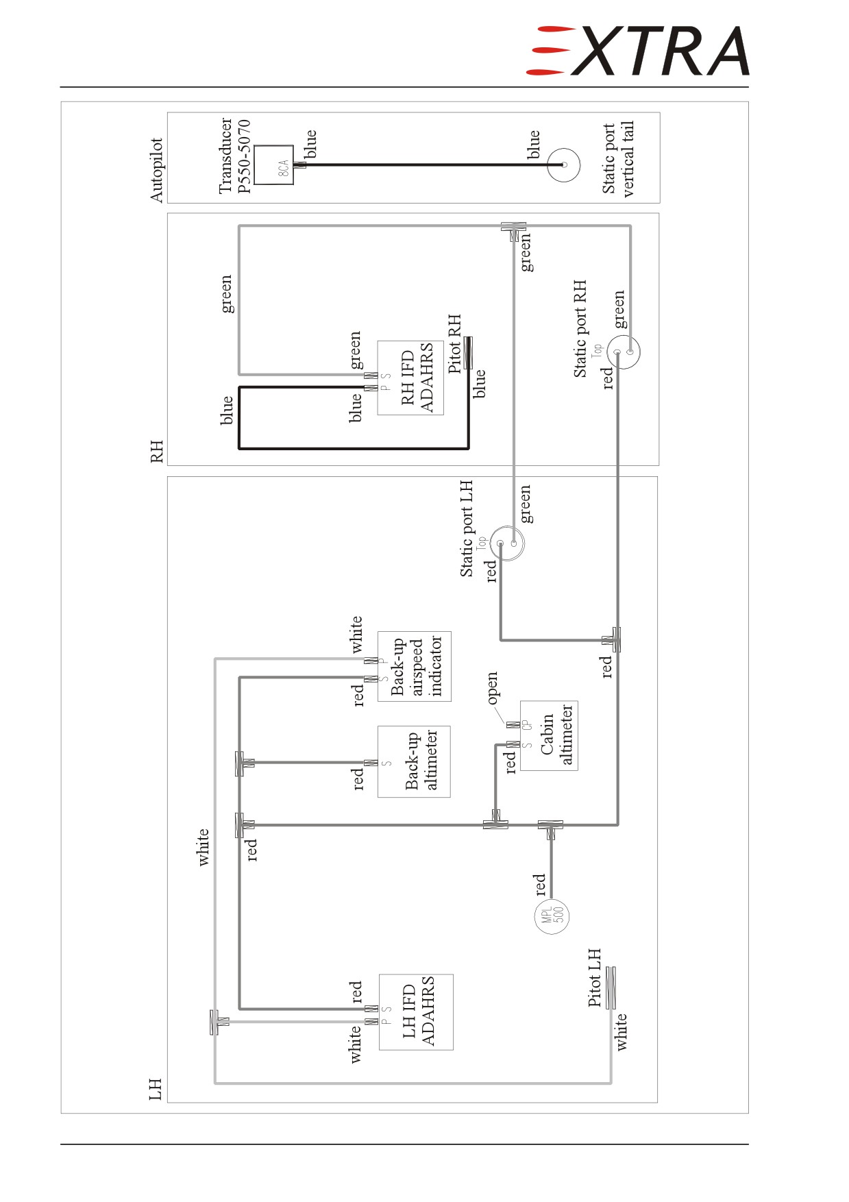
Figure 34-1
Pitot Static System Schematic
Page 6 34
34-10-00
FLIGHT ENVIRONMENTAL DATA
NOTE
When any connections in the static system are opened for checking, a static
leak check per AC 43-6C §9a must be performed.
34-10-01
Altimeter (2” type)
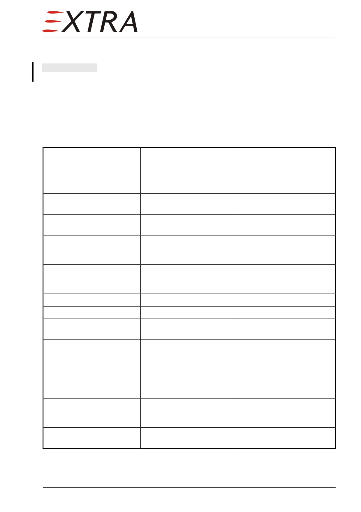
Troubleshooting
Complaint
Possible Cause
Remedy
Excessive scale error
Improper calibration
Contact manufacturer
adjustment
Excessive pointer oscillation
Defective mechanism
Contact manufacturer
High or low reading
Improper venting
Eliminate leak in static
pressure system
Setting knob is hard to turn
Wrong lubrication or lack of
Contact manufacturer
lubrication
Inner reference marker fails to
Out of engagement
Contact manufacturer
move when setting knob is
rotated
Setting knob set screw loose
Not tight when altimeter was
Tighten instrument screw, if
or missing
reset
loose. Contact manufacturer, if
screw is missing
Cracked or loose cover glass
Case gasket hardened
Contact manufacturer
Dull or discolored markings
Age
Barometric scale and reference
Slippage of mating parts
Contact manufacturer
markers out of synchronism
Barometric scale and reference
Drift in mechanism
Contact manufacturer
markers out of synchronism
with pointers
Altimeter sticks at altitude or
Water or restriction in static
Remove static lines from all
does not change with change
line
instruments; blow line clear
of altitude
from cockpit to static ports
Altimeter changes reading as
Water in static line
Remove static lines from all
aircraft is banked
instruments; blow lines clear
from cockpit to static ports
Altimeter requires resetting
Temperature compensator
Contact manufacturer
frequently
inoperative
Page Date:
34 Page 7