Extra 500. Maintenance Manual (2012) - page 14
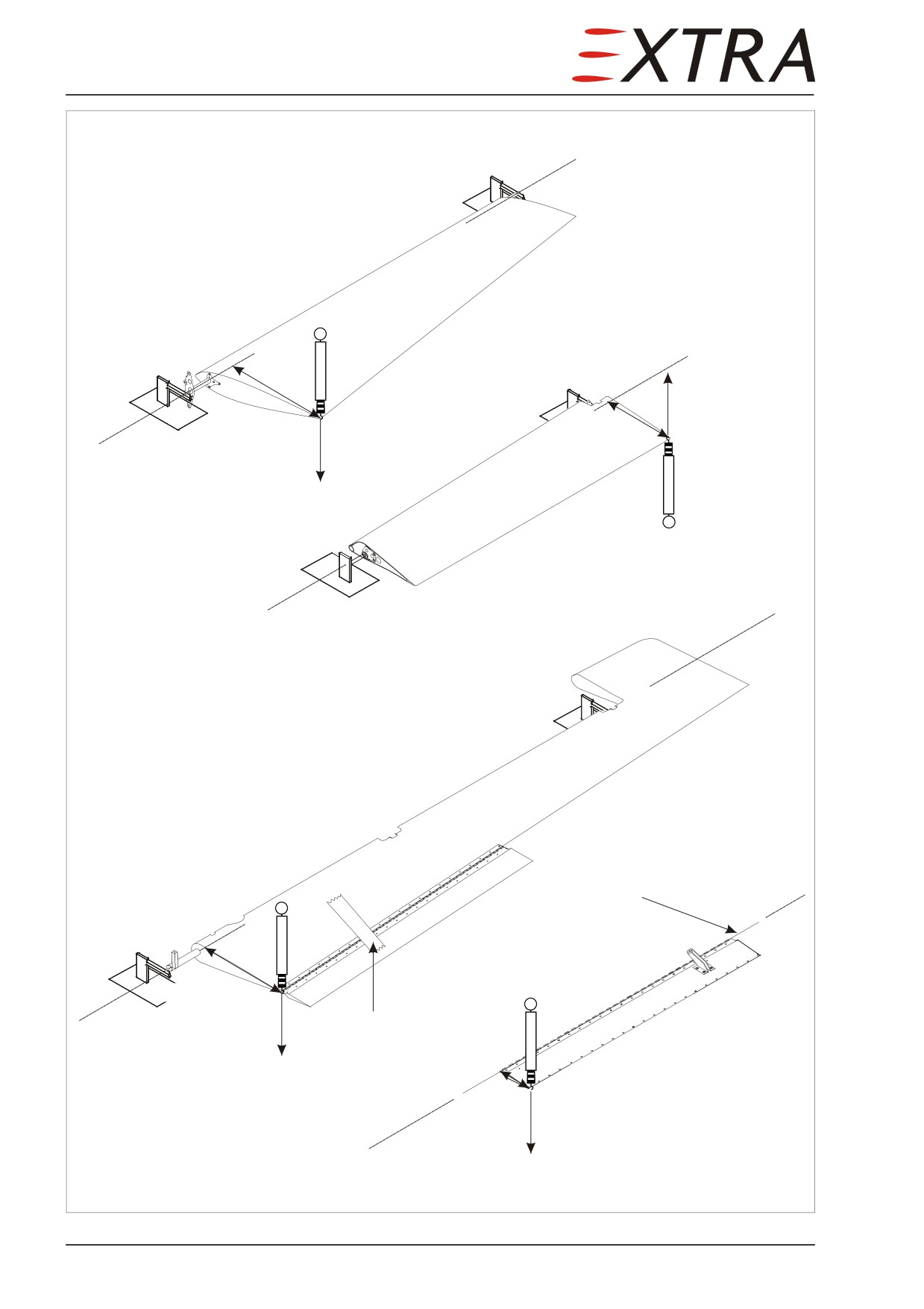
Hinge center axis
Rudder
r
-m
Weighing point
r
Weighing point
m
Aileron
Hinge center axis
Hinge center axis
Elevator (RH)
Wire
r
Weighing point
Tape
Trim tab
m
r
Weighing point
m
Hinge center axis
Figure 51-3
Control Surface Balancing
Page 24 51
Page Date:
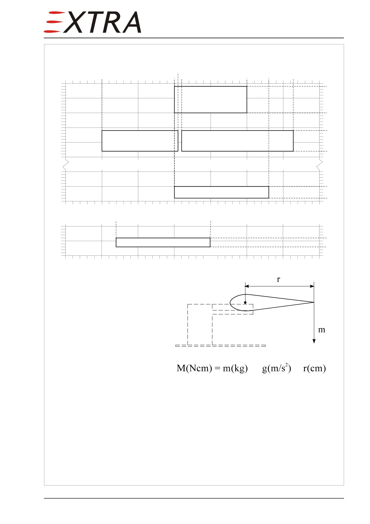
Permissible Weights and Moments
5.53
4.5
5.5
5.6
6.5
6.8
7.13
450
440
400
Rudder
350
350
300
290
250
Elevator (LH)
Elevator (RH)
220
200
50
0
0
Aileron
-40
-50
4.0
4.5
5.0
5.5
6.0
6.5
7.0
7.5
0.37
0.50
50
30
25
Trim tab
15
0
0.30
0.35
0.40
0.45
0.50
0.55
0.60
0.65
Weights
Aileron LH:
(W)
kg
Aileron RH:
(W)
kg
Rudder:
(W)
kg
Elevator LH:
(W)
kg
Elevator RH:
(W)
kg
Trim Tab:
(W)
kg
x
x
Moments
2
Aileron LH:
(m:)
kg x 9.81m/s
x
(r:)
cm = (M:)
Ncm
2
Aileron RH:
(m:)
kg x 9.81m/s
x
(r:)
cm = (M:)
Ncm
2
Rudder:
(m:)
kg
x
9.81m/s
x
(r:)
cm = (M:)
Ncm
2
Elevator LH:
(m:)
kg
x
9.81m/s
x
(r:)
cm = (M:)
Ncm
2
Elevator RH:
(m:)
cm = (M:)
Ncm
2
Trim Tab:
(m:)
kg
x
9.81m/s
x
(r:)
cm = (M:)
Ncm
Figure 51-4
Permissible Weights and Moments
Page Date:9. August 2013
51 Page 25
51-70-00
REPAIRS
51-70-01
Repair of Reinforced Glass and Carbon Fibre
Components
IMPORTANT
Repair of composite parts has to be carried out only by qualified and
authorized personnel.
If the aircraft is damaged, proceed as follows. First conduct a careful visual
inspection of the surface and the damaged area. Frequently, the damage
extends to further components, sometimes a fracture will continue invisible
beneath the surface.
Perform the repair work with utmost care. The external shell of the wing and
empennage as well as all structural parts including the fuselage are stressed; a
failure of this bonded structure can lead to an aircraft crash. In order to
eliminate dangerous stress concentrations, avoid changes in cross-sectional
areas.
IMPORTANT
The resin-hardener mixture ratio must be precisely maintained (± 0.5 %).
Clean cups and tools must be used. The weight ratio of fabric to resin
mixture should be approximately 50:50.
Immediately prior to applying the wet laminate, sand and vacuum clean the
repair area, so that no dirt and dust is involved which could prevent a secure
adhesion.
Sanding carbon and glass fibre laminates gives off a fine dust that may
WARNING
cause skin and/or respiratory irritation unless suitable skin and
respiration protection is used.
Carbon-tetracloride or Acetone used for cleaning repair areas are
WARNING
flammable liquids and should be used with proper ventilation and safety
equipment.
IMPORTANT
As with plywood grain, the direction of the various fibres (longitudinal or
diagonal) is of great importance for the stability.
The number of layers required to restore the stability in the damaged area can
be taken from the layer sequence / placement plan. (Refer to the respective
Chapters)
It is necessary to know the number and direction of layers in the damaged area,
in order to be able to replace them with the original number. In all cases, the
thickness of the laminate has to be measured with a vernier calliper for the
exact determination of the laminate thickness.
One technique to learn about the number of layers is to burn a small piece
taken from the damaged area. The resin will burn off, leaving the glass and/or
carbon fabric to be inspected for the number of layers and the type of fabric.
Creating a scarfed overlap takes time. Sand away as much of the old material,
so that the new fabric patches do not project beyond the contour.
Page 26 51
Page Date:
In order to shorten the curing time, a heater can be used to increase the ambient
temperature.
Too high temperature will cause large air bubbles in the laminate. Local
CAUTION overtemperature can be prevented by using a foil tent which leads the hot
air stream.
The curing cycle must be maintained as stated. Use a thermometer to monitor
the temperature.
IMPORTANT After repair of control surfaces, check for proper balance (Manufacturer
will provide service instructions to manufacturer authorized repair
stations).
It is recommended to prepare test specimen at the same time as the actual
repair is accomplished. These can then be subject to a material test to establish
the quality of the laminate in the repaired part. To make this determination
valid, the specimen must be assembled with the same style of fabric and resin
mixture. Subsequently the specimen must be subject to the curing pressure,
temperature and time identical with those in the actual repair.
Page Date:9. August 2013
51 Page 27
51-70-02
Repair of Sandwich Material
Three types of core materials are used for sandwich on the EXTRA 500:
1 PMI or PVC hard foam,
2 Honeycomb
3 Plywood,
with carbon fibre shells.
The following section describes the repair of these types of sandwich. Different
processing techniques for these materials, if necessary, are also described.
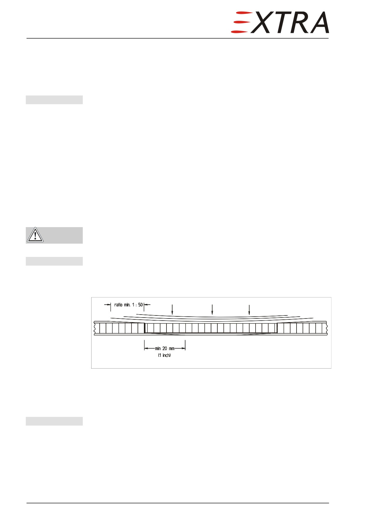
a) Minor Surface Damage
Around a visible crack, the laminate may be separated from the core material.
Determine the extent of this area by coin tapping. Remove the separated
laminate carefully using a sanding disk, sanding block or a sharp knife. Prepare
a scarfed overlap of the laminate around the damaged area. Overlap lenght per
fabric layer min. 20 mm.
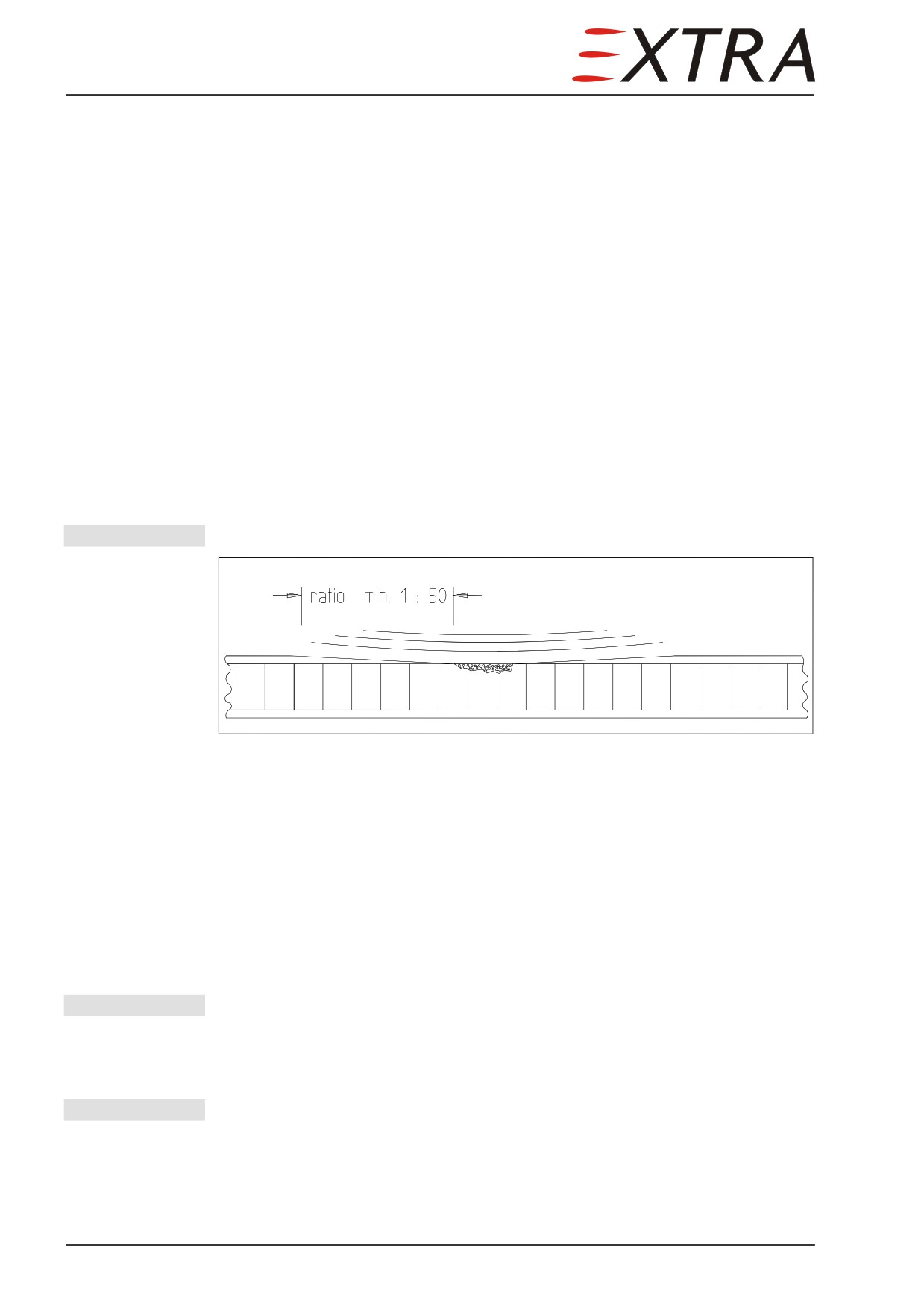
IMPORTANT Ratio (laminate thickness : overlay lenght) min. 1 : 50
Figure 51-5
Minor Surface Damage
After preparing the scarfed overlap, clean the repair area thoroughly as follows:
1 Remove the sanding dust with a pneumatic vacuum cleaner
2 Clean the scarfed overlaps with carbon-tetrachloride or acetone in case of dirt
or grease was trapped during the preparation
Damaged core material has to refilled with a mixture of resin and
microballoons (weight ratio 100:15). Apply resin mixture to the repair area and
lay on fabric in accordance to the layer sequence plans. Ensure to use correct
style and direction of fabric.
IMPORTANT Repair area must be clean of dirt, dust and grease!
Lay out the required number and size of fabric pieces on a piece of colored
plastic foil and soak (wet) them with resin mixture; subsequently position them
on the repair area.
IMPORTANT Remove the plastic foil after each positioning process.
For a repair of honeycomb sandwich parts you have to observe the following:
The repair area has to be cured under condition of vacuum bagging.
For vacuum bagging, proceed as follows:
1 Apply nylon peel ply on the last repair fabric layer.
Page 28 51
Page Date:
2 Perforate a clean, thin plastic foil with a thick needle (max.spacing of holes:
20 mm x 20 mm) - mainly in the area of the honeycomb - and lay it on the
repair area.
3 Lay a jute cloth (weave) or equivalent bleeder cloth on this perforated plastic
foil.
4 Lay an air tight plastic foil upon the jute weave and seal their edges to the
surrounding surface using an adhesive tape.
5 Apply suction with a vacuum pump (pressure approx. .7 bar/ 10 psi).
6 Apply the thermal curing cycle.
7 Following the curing cycle remove vacuum bagging material and nylon peel
ply.
NOTE
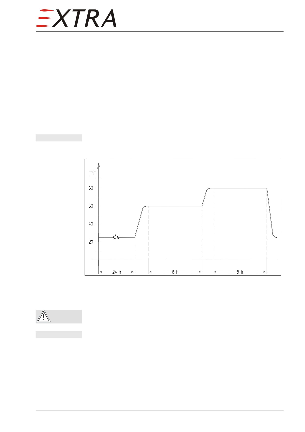
After the pre-curing period at room temperature, the repaired area has to
be cured according to the temperature cycle as showed below.
Figure 51-6
Curing Cycle Resin L 20 / SL
After the curing process is completed, the repair area can be sand leveled to the
surrounding area.
Sand only the edge thickness of repair laminate.
CAUTION
NOTE
For painting of the repair area refer to Chapter 51-70-06.
b) Damage of Complete Sandwich
If the inner laminate is also damaged, first remove the upper laminate within
the area, where no secure bond connection to the core material is suspected.
Trim out the complete damaged portion of core material to a circular or
elliptical shape.
The damaged area of the inner laminate has to be taken out as well. Make sure
not to increase the disbond area by preparing the hole. Preferably use a hand
held milling machine. In case of cutting with a saw, the pulsation stress may
Page Date:9. August 2013
51 Page 29
peel off the inner laminate (secondary damage). If the extent of the disbonded
area on the inner laminate exceeds the prepared cut out, increase the cut out of
material and upper laminate.
Prepare a scarfed overlap of laminate around the circular cut out. Overlap
lenght of inner laminate should not be less than 20 mm.
IMPORTANT
Ratio (laminate thickness : overlay lenght) min. 1 : 50
Prepare a replacement block of core material
(foam or honeycomb) with
equivalent diameter and thickness. Cut it to fit snuggly in the trimed hole. In
case of foam core, coat one side with a mixture of resin and microballoons
(ratio 100:15). Apply prelaminated fabric layers required for the inner laminate
on this side of the core filler block. Ensure correct style and direction of fabric.
After precuring the laminate at elevated room temperature (30°C), scarf the
overlap and sand the upper overlapping core material down, up to the
surrounding core material.
Subsequently clean the repair area thoroughly as follows:
1
Remove the sanding dust with a pneumatic vacuum cleaner.
2
Clean the scarfed overlaps with carbon-tetrachloride or acetone in case of dirt
or grease was trapped during the preparation.
Carbon-tetrachloride or acetone used for cleaning repair areas are
WARNING
flammable liquids and should be used with proper ventilation and safety
equipment.
IMPORTANT
Repair area must be free of dirt and grease.
Wet all surfaces of the backing plate and the scarfed area with resin mixture.
Lay on prelaminated fabric layer in accordance to the layer sequence plan.
Ensure correct style and direction of fabric.
Figure 51-7
Damage of Complete Sandwich
Lay out the required number and size of fabric pieces on a piece of plastic foil
and wet them with resin mixture. Subsequently position them on the repair
area.
IMPORTANT Remove the plastic foil after each positioning process.
The repair area has to be cured under condition of vacuum bagging. Proceed as
follows:
1 Apply nylon peel ply on the last repair fabric layer.
2 Perforate a clean, thin plastic foil with a thick needle (max.spacing of holes:
20 mm x 20 mm) - mainly in the area of the honeycomb - and lay it on the
repair area.
Page 30 51
Page Date:
3 Lay a jute cloth (weave) or equivalent bleeder cloth on this perforated plastic
foil.
4 Lay a second plastic foil upon the jute weave and seal their edges to the
surrounding surface using an adhesive tape.
5 Apply suction with a vacuum pump (pressure approx. .7 bar/ 10 psi).
6 Apply the thermal curing cycle.
7 Following the curing cycle carefully remove vacuum bagging material and
nylon peel ply.
NOTE
After the pre-curing period at room temperature, the repaired area has to
be cured according to the temperature cycle as given by the laminate's
manufacturer.
After the curing process is completed, remove the nylon peel ply. The repaired
area can be sand leveled with the surrounding area.
Sand only the edge thickness of repair laminate!
CAUTION
NOTE
For painting of the repair area proceed like mentioned in
Chapter 51-70-06.
Page Date:9. August 2013
51 Page 31
51-70-03
Repair of Laminates
Minor Damage
Scarf the edges of the minor damage area with sandpaper. Minimum lenght of
scarf per fabric layer approx. 20 mm; ratio (laminate thickness : scarf lenght)
approx. 1: 50.
Following the scarf procedure, clean the repair area thoroughly:
1
Remove the sanding dust with a pneumatic vacuum cleaner
2
Clean the scarfed overlaps with carbon-tetrachloride or acetone in case of dirt
or grease was introdued during the preparation.
Repair area must be free of dirt, dust and grease.
CAUTION
Wet the prepared scarfed areas with resin mixture. Lay on prelaminated fabric
layer in accordance to the layer sequence plan. Ensure correct style and
direction of fabric. Apply nylon peel ply on the last repair fabric layer.
NOTE
Lay out the required number and size of fabric pieces on a piece of colored
plastic foil and wet them with resin mixture. Subsequently position them
on the repair area.
IMPORTANT
Remove the plastic foil after each positioning process.
After the curing process has been completed, remove the nylon peel ply. The
repair area can be sand leveled with the surrounding area.
Sand only the edge thickness of repair laminate!
CAUTION
Refinish the surface according Chapter 51-70-06 (Painting).
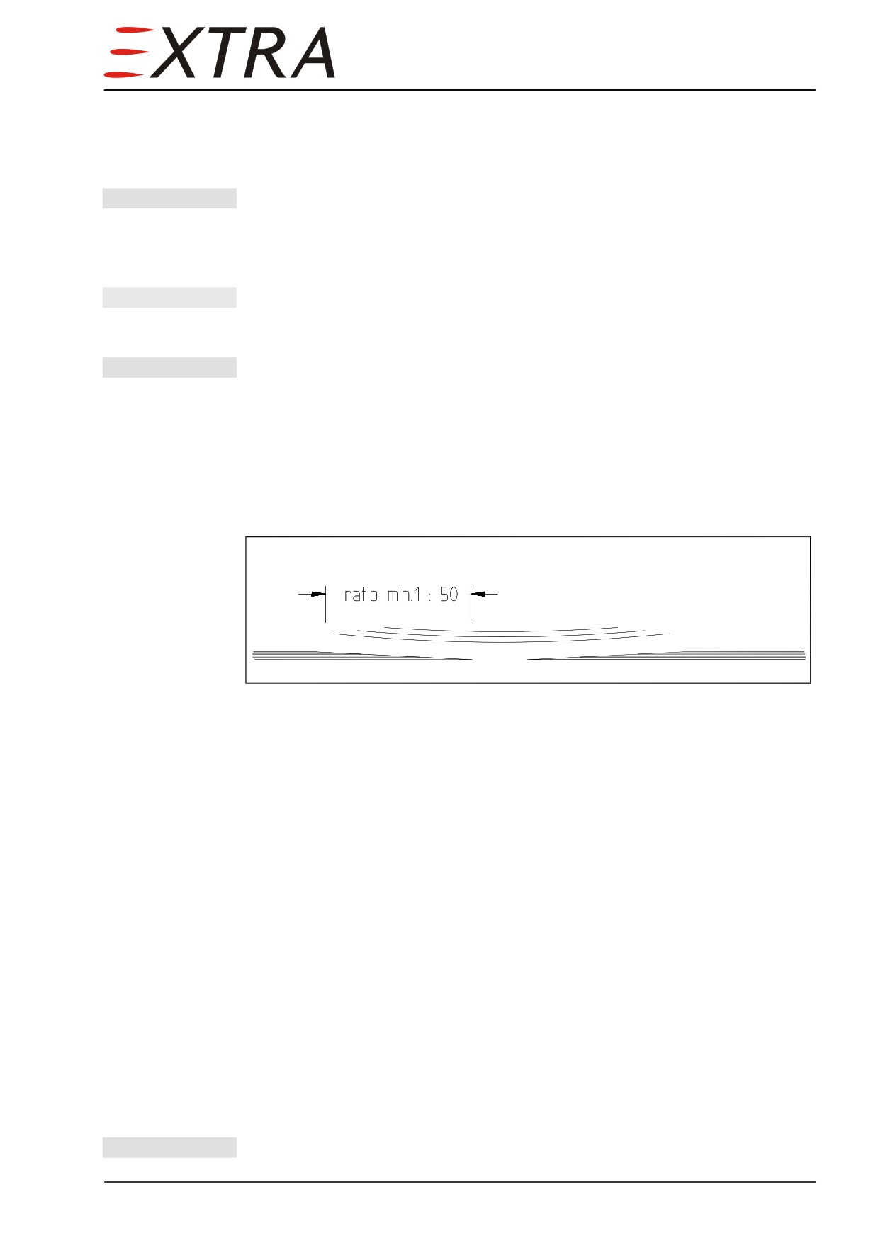
If the extent of the damaged area exceeds 10 cm (4 inches) a large damage
repair is required.
Carefully trim out the damaged portion to a circular or oval shape.
Prelaminate a backing plate from two layers of glass fibre fabric and resin
mixture, which must be approx. 20 mm larger than the damaged area. Apply
nylon peel ply as external layer. Sandwich the resin wetted layers between two
sheets of plastic foil.
Work the excess resin out and allow the plate to cure at elevated room
temperature for 8 hours on a flat surface or a plasticfoil-covered surface of the
proper curvature near the damaged area, or the same location on a comparable
undamaged part.
Following the curing cycle remove plastic foil and nylon peel ply. Bond the
backing plate to the inside using a mixture of resin and cotton flocks, and adapt
to the contour. Cure the bonding at elevated room temperature for 8 hours.
Subsequently scarf the edges of the damaged portion with sandpaper.
Minimum lenght of scarf per fabric layer approx. 20 mm.
IMPORTANT
Ratio (laminate thickness : scarf lenght) approx. 1: 50.
Following the scarf procedure, clean the repair area thoroughly:
Page 32 51
Page Date:
1 Remove the sanding dust with a pneumatic vacuum cleaner
2 Clean the scarfed overlaps with carbon-tetrachloride or acetone in case of dirt
or grease was trapped during the preparation of the overlap.
IMPORTANT Repair area must be free of dirt, dust and grease.
Wet all surfaces of the backing plate and the scarfed area with resin mixture.
Lay on prelaminated fabric layer in accordance to the layer sequence plan.
Ensure correct style and direction of fabric.
NOTE
Lay out the required number and size of fabric pieces on a piece of colored
plastic foil and wet them with resin mixture. Subsequently position them
on the repair area.
IMPORTANT Remove the plastic foil after each positioning process.
The repair area has to be cured under condition of vacuum bagging. Proceed as
follows:
1 Apply nylon peel ply on the last repair fabric layer
2 Perforate a clean, thin plastic foil with a thick needle (max. spacing of holes:
20 mm x 20 mm) - mainly in the area of the honeycomb - and lay it on the
repair area.
Figure 51-8
Repair of Minor Damage
Large Damage
If the extent of the damaged area exceeds 100 mm (4 inches) a large damage
repair is required.
Carefully trim out the damaged portion to a circular or oval shape.
Prelaminate a backing plate from two layers of glass fibre fabric and resin
mixture, which must be approx. 20 mm larger than the damaged area. Apply
nylon peel ply as external layer. Sandwich the resin wetted layers between two
sheets of plastic foil. Work the excess resin out and allow the plate to cure at
elevated room temperature for 8 hours on a flat surface or a plasticfoil-covered
surface of the proper curvature near the damaged area, or the same location on
a comparable undamaged part.
Following the curing cycle remove plastic foil and nylon peel ply. Bond the
backing plate to the inside using a mixture of resin and cotton flocks, and adapt
to the contour. Cure the bonding at elevated room temperature for 8 hours.
Subsequently scarf the edges of the damaged portion with sandpaper.
Minimum lenght of scarf per fabric layer approx. 20 mm.
IMPORTANT Ratio (laminate thickness : scarf lenght) approx. 1: 50.
Page Date:9. August 2013
51 Page 33
Following the scarf procedure, clean the repair area thoroughly:
1
Remove the sanding dust with a pneumatic vacuum cleaner
2
Clean the scarfed overlaps with carbon-tetrachloride or acetone in case of dirt
or grease was trapped during the preparation of the overlap.
IMPORTANT
Repair area must be free of dirt, dust and grease.
Wet all surfaces of the backing plate and the scarfed area with resin mixture.
Lay on prelaminated fabric layer in accordance to the layer sequence plan.
Ensure correct style and direction of fabric.
NOTE
Lay out the required number and size of fabric pieces on a piece of colored
plastic foil and wet them with resin mixture. Subsequently position them
on the repair area.
IMPORTANT
Remove the plastic foil after each positioning process.
The repair area has to be cured under condition of vacuum bagging. Proceed as
follows:
1
Apply nylon peel ply on the last repair fabric layer.
2
Perforate a clean, thin plastic foil with a thick needle (max.spacing of holes:
20 mm x 20 mm) - mainly in the area of the honeycomb - and lay it on the
repair area.
3
Lay a jute cloth or equivalent bleeder cloth on this perforated plastic foil.
4
Lay an air tight plastic foil upon the jute weave and seal their edges to the
surrounding surface using an adhesive tape.
5
Apply suction with a vacuum pump (pressure approx. .7 bar/ 10 psi).
6
Apply the thermal curing cycle.
7
Following the curing cycle carefully remove vacuum bagging material and
nylon peel ply.
NOTE
After the pre-curing period at room temperature, the repaired area has to
be cured according to the temperature cycle as given by the laminate's
manufacturer.
After the curing process is completed, the repair area can be sand leveled to the
surrounding area.
Sand only the edge thickness of repair laminate!
CAUTION
Refinish the surface according Chapter 51-70-06.
Page 34 51
Page Date:
51-70-04
Repair of Spars and Elements of the Pressure Cabin
IMPORTANT The spars and structural elements of the pressure cabin are highly
stressed; a failure of this bonded structure can result in loss of the
aircraft! In all cases, the repair must be considered as a large-scale repair
with a Damage Class 1 (Refer to Chapter 51-10-01 Damage Classification).
EXTRA has to be contacted prior to repair!
Structural elements of the pressure cabin
The pressurized part of the fuselage runs from the front bulkhead (firewall
position) to the rear pressure dome positioned at X6125. Main structure
elements are: Flat front bulkhead, skin, frames, longerons, keel beams and the
rear pressure dome
(GRP). The height of the honeycomb core in the
pressurized part is
30 mm (except shell below the wing). Longerons are
integrated in the skin sandwich.
Spars of Wing and Empennage
The spars consist of carbon fibre roving or UD-tape caps, carbon fibre webs
and PMI foam or plywood/honeycomb cores.
51-70-05
Structural Repair of Steel Components
Restoration of damaged steel designed structures to their original design
strength, shape and alignment involves careful evaluation of the damage,
followed by exacting workmenship in performing the repairs.
IMPORTANT Should structural repairs practicable on the aircraft be necessary, refer to
"Aircraft Inspection and Repair FAA AC 43.13-1B Chapter 4 (Metal
Structure, Welding and Brazing)" latest change.
IMPORTANT Alterations or repair of the airplane must be accomplished by licensed
personnel. Consult EXTRA in case of doubt about a repair not specifically
mentioned there.
Consider, that different types of steel are being used on the aircraft structures,
so as steel tubes, brackets, connections etc. (WLB 1.7734.4 and AISI 4130 N
type steel).
The two steel types shall not be mixed in repair.
Also refer to Chapter 51-30-02.
NOTE
If welding work must be performed, use only the TIG procedure (Tungsten
Inert Gas). Use welding wire
1.7734.2 for
1.7734.4 and AISI 4130 N or
equivalent, depending on the respective steel type, for welding additive.
Page Date:9. August 2013
51 Page 35
51-70-06
Painting of Composite Parts
Coating materials may cause sensitization by inhalation and skin contact.
WARNING
Hardeners and coating materials ready for use can have an irritant and
sensitizing effect upon the skin and respiratory tracts and cause allergic
reactions.
Provide for a continuous supply of fresh air during and also after the
WARNING
application, do not inhale the vapors and wear a breathing mask during
the spray application of these materials. Persons suffering from an allergy
or being prone to diseases of the respiratory tracts must not get in contact
with coating materials. Refer to the manufacturer technical information
sheet!
After curing cycle the surface of repared area can be sanded with sandpaper
(80 grade). Indentations are filled with Presto putty light. Subsequently achieve
a surface as uniformly rough as possible using a finer dry sandpaper (150 or
320 grade). Prior to paint application, the surface of the repair area must be
cleaned thoroughly of all sanding dust, separation compounds and other
foreign materials. Subsequently apply 285-100 VOC Glassodur
Rapidfüller
with a spray gun.
NOTE
The Rapidfüller (rapidfiller) must be completely dry before the covering paint
can be applied.
For the final sanding, use 400 grade wet sandpaper to achieve a smooth clean
surface. Allow surface to dry. Paint application of 22, 55 or 90 Glassodur
Decklack is performed with a spray gun.
Paint can be mixed with small quantities of reducer.
After completion of the painting, polish the repair area.
Page 36 51
Page Date:
51-70-07
Aluminium and Steel Components Refinishing
Complete procedure necessary to remove existing paint from aluminium and
steel components and then to repaint them as described in the following
paragraphs.
Degreasing
Cleaning solvents can be toxic and volatile. Use only in well ventilated
WARNING
areas. Avoid physical contact with solvent and do not inhale vapors. Keep
solvent containers covered when not in use.
Before stripping parts, remove all fittings, O-rings, nuts, bolts, washers,
CAUTION
pistons, bearing cups, etc.
1
Clean all metal parts by immersing in a clean degreasing solution. An alkaline
based solution is recommended for aluminium and magnesium parts.
2
Hardened dirt or grease may be removed with soft bristle brush, or by soaking
in cleaning solution.
3
Where necessary clean bearing cones carefully in a separate container of clean
solvent.
Do not spin bearing cones with compressed air.
CAUTION
4
After cleaning, thoroughly dry all metal parts with filtered, dry compressed air.
5
It is recommended that all O-rings, backup rings, and wipers be replaced at
each overhaul. However, if necessary, O-rings may be reused, but should be
put back into that position from which they had been removed.
6
Wipe down O-rings, backup rings, wipers, or other rubber parts with a clean
dry cloth. Lubricate with a suitable O-ring lubricant prior to installation.
Paint Removal
Disassemble components to the level required for repainting, then proceed as
follows.
Stripping solvents can be toxic and volatile. Use only in well ventilated
WARNING
areas. Avoid physical contact with solvent and do not inhale vapors. Keep
solvent containers covered when not in use.
Before stripping parts, remove all fittings, O-rings, nuts, bolts, washers,
CAUTION
pistons, bearing cups, etc. Parts must be totally immersed in solvent, to
maximize cleaning.
1
Degrease part as per degreasing paragraph.
2
Totally immerse part in paint removing solvent. Portions not totally covered by
solvent will begin to corrode.
NOTE
Stripping agents are commercially available for removing topcoat and
primer. Follow manufacturer's recommendations for use and disposal of
stripping solutions.
3
Remove part from solvent and rinse thoroughly with water heated to 160° to
180°F (71° to 82° C). Flush solvent from all cavities and threaded holes where
Page Date:9. August 2013
51 Page 37
entrapment might occur.
4
Thoroughly dry part with filtered, dry compressed air.
5
Where applicable refer to inspection procedures given in the respective
chapters for specific parts to locate possible defects.
NOTE
Refinishing should be completed as soon as possible; unprotected parts
will begin to corrode.
Repainting
Paint all surfaces except those which are subjected to friction (bearing surfaces,
anchor bolt bores, etc.). Proceed as follows:
1
Parts to be repainted should be cleaned and stripped as per instruction in
degreasing and paint removal paragraphs.
2
Aluminium parts should have a protective barrier between the topcoat and base
metal. It is recommended that they are treated with solutions listed in Chapter
51-30.
3
Apply solution liberally and evenly. Allow solution to set from 1 to 5 minutes.
The solution must completely wet the surface and overlap onto the adjoining
anodize.
4
Remove excess coating by flushing with clean water.
5
Paint parts with one coat of wash primer. Allow to dry thoroughly.
6
Paint parts with one coat of lacquer listed in Section 51-30. Allow to dry
thoroughly before reassembly.
Page 38 51
Page Date:
Chapter 52
Doors
52 Page 1
Table of Contents
52-00-00
GENERAL
3
Troubleshooting
3
52-10-00
PASSENGER/CREW
4
Description
4
52-10-01
Upper Door Paneling
6
Removal/Installation
6
52-10-02
Lower Door Paneling
6
Removal/Installation
6
52-10-03
Central Door Operating Device
7
Removal/Disassembly
7
Inspection (After Teardown)
7
Installation/Assembly
8
52-10-04
Lower Door Operating Device
10
Removal/Disassembly
10
Inspection
10
Installation/Assembly
10
52-10-05
Door Locking Mechanism
12
Disassembly/Assembly
12
Rigging
12
52-10-06
Door Seal
14
Removal/Installation
14
52-10-07
Sill Seal
15
Removal
15
Installation
15
52-10-08
Door Switch
17
Removal/Installation
17
Adjustment
17
52-20-00
EMERGENCY EXIT
18
Description
18
52-20-01
Emergency Exit Seal
18
Removal/Installation
18
Page 2 52
Page Date: 9. August 2013
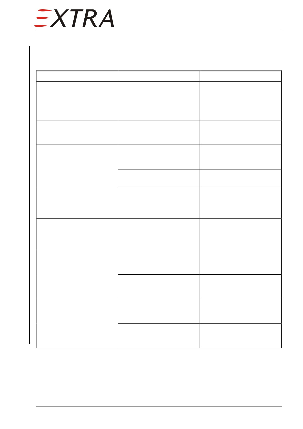
52-00-00
GENERAL
Troubleshooting
Complaint
Possible Cause
Remedy
Pressure cabin leakage
Erroneous cabin door or
Check seals for damages and
emergency exit seal
correct installation. If seal is
installation or damaged seal
damaged replace it as per
Section 52-10-06 and 52-20-
01
Exterior door locking
Rotation of outer door handle
Replace central door operating
mechanism damaged
without previously pulling it
device as per Section 52-10-03
against its stop
Unusual high operating forces
Misadjusted locking
Perform Door Locking
or lacking ability to reach the
mechanism
Mechanism Rigging as per
fully open or closed position
Section 52-10-05
of actuation handles
Lacking lubrication
Remove door paneling, clean
and lubricate mechanism
Damaged or worn locking
Replace damaged or worn
mechanism
parts. Perform Door Locking
Mechanism Rigging. Refer to
Section 52-10-05
Faultive mechanical locking
Mechanically damaged
Replace damaged or worn
indication (8 sight glasses)
indication or locking
parts. Perform Door Locking
mechanism
Mechanism Rigging. Refer to
Section 52-10-05
Door warning light does not
Light, wiring or switch
Identify and replace
illuminate with door open
defective
component as per Section 52-
10-07.
Door switch misadjusted
Perform Door Switch
Adjustment as per Section 52-
10-07.
Door warning light illuminates
Wiring or switch defective
Identify and replace
in spite of closed door
component as per Section 52-
10-07.
Door switch misadjusted
Perform Door Switch
Adjustment as per Section 52-
10-07.
Page Date:
52 Page 3
52-10-00
PASSENGER/CREW
Description
The entry door at the left side of the fuselage is a two-section, outward opening
door. The upper part folds up held in upper position by a telescopic lift
cylinder, and the lower part folds down, limited by two cables and provides a
step for easy in boarding and deplaning passengers.
Upper door could damage the left wing flap.
CAUTION Ensure wing flaps are retracted before opening the door.
For opening the door from outside, pull outer handle completely out, turn
handle clockwise and deploy upper door. Then rotate up the sill lever which is
now accessible on the lower door, stand clear and deploy the lower door.
For opening the door from inside, press safety button, turn inner handle
counterclockwise and deploy upper door. Then rotate up the sill lever which is
now accessible on the lower door, stand clear and deploy the lower door.
Door locking pins could damage the door frame.
CAUTION Ensure handles are in the open position before closing upper or lower
door.
For closing the doors reverse the above given procedure. Ensure that outer
handle is sunk, inner handle is locked and all eight inspection glasses inside
show green color.
Page 4 52
Page Date: 9. August 2013
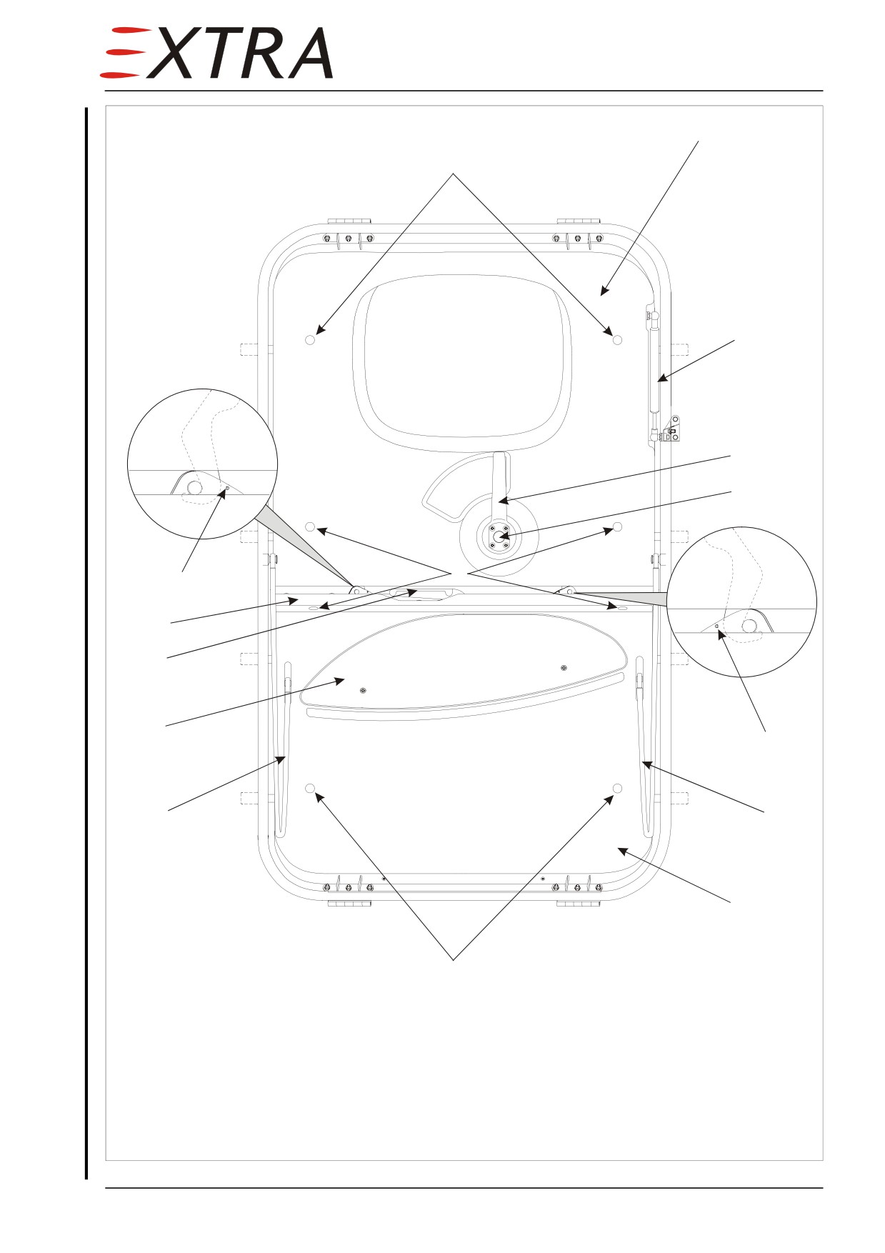
View from inside
1
8
2
3
4
8
5
11
10
9
5
6
6
7
8
Legend:
1
upper door paneling
7
lower door paneling
2
telescopic lift cylinder
8
inspection glas
3
upper door inner handle
9
foot step
4
safety button
10 sill lever handle doubler
5
check hole
11 clamping strip
6
arresting cable
Figure 52-1
Door
Page Date:
52 Page 5
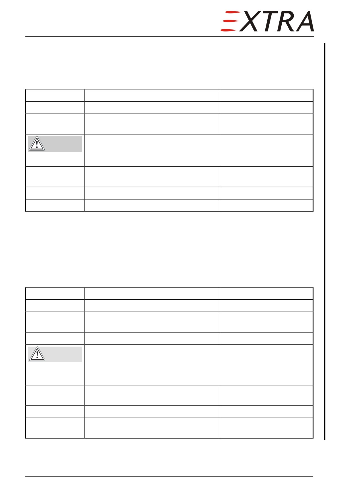
52-10-01
Upper Door Paneling
Removal/Installation
Refer to Figure 52-1
Detail Steps/Work Items
Key Items
1
Open door completely.
2
Remove button housing, safety button (4),
4 bolts
inner handle (3) and spring.
see also Figure 52-2
Not supported upper door could cause injuries by lodging.
WARNING
Let a helping person hold the upper door in open position.
Close upper door with care.
3
Disconnect telescopic (2) lift cylinder from
the door.
4
Remove the upper door paneling (1).
9 screws
5
Install in reverse sequence of removal.
52-10-02
Lower Door Paneling
Removal/Installation
Refer to Figure 52-1
Detail Steps/Work Items
Key Items
1
Open door completely.
2
Remove sill lever handle doubler (10) from
2 bolts
lower door actuator lever.
3
Remove the clamping strip (11).
Not arrested lower door could damage aircraft structure and lower door
CAUTION
hinges.
Support lower door at sufficient height, when removing the arresting
cables.
4
Disconnect arresting cables (6) from door
frame.
5
Remove the lower door paneling (7).
4 screws
6
Install in reverse sequence of removal.
2 bolts of step 2 must be
installed with Loctite 243
Page 6 52
Page Date:
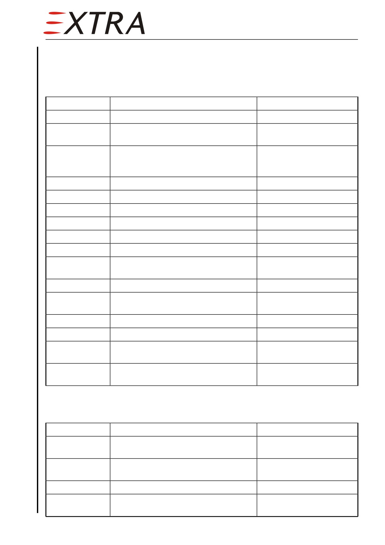
52-10-03
Central Door Operating Device
Removal/Disassembly
Refer to Figure 52-2
Detail Steps/Work Items
Key Items
1
Remove the upper door paneling.
Refer to Chapter 52-10-01
2
Disconnect pushrods and gas spring from
actuator (11) and inner handle bearer (6).
3
Remove slotted spring pin (7) holding the
Relieve spring by pulling at
spring (8).
the spring eye with a bent
wire.
4
Remove inner handle bearer (6).
5
Remove slotted spring pin (9).
6
Remove inner guide pin (10).
7
Remove actuator (11).
8
Remove slotted set screw (15).
9
Remove outer guide pin (16).
10
Remove shafting axle (18) including outer
handle (20).
11
Remove collar bushing (17).
12
Remove dowel pin (19) to take out the
Dowel pin is glued in with
spring (8).
Loctite 243
13
Remove flange bushings (12).
14
Remove outer handle bearing (13)
4 bolts
15
Separate outer handle (20) from shafting
4 bolts
axle (18).
16
Remove slotted spring pin (3) from safety
button (2).
Inspection (After Teardown)
Refer to Figure 52-2
Detail Steps/Work Items
Key Items
1
Inspect sliding surfaces for damage and
Replace parts if necessary
cracks.
2
Inspect the shafting axle (18) slot for burrs
and torsional bending.
3
Inspect guide pins (10/16) for wear.
Replace parts if necessary
4
Inspect slotted spring pins (3/7/9) for
Replace parts if necessary
bending or other damage.
Page Date:
52 Page 7
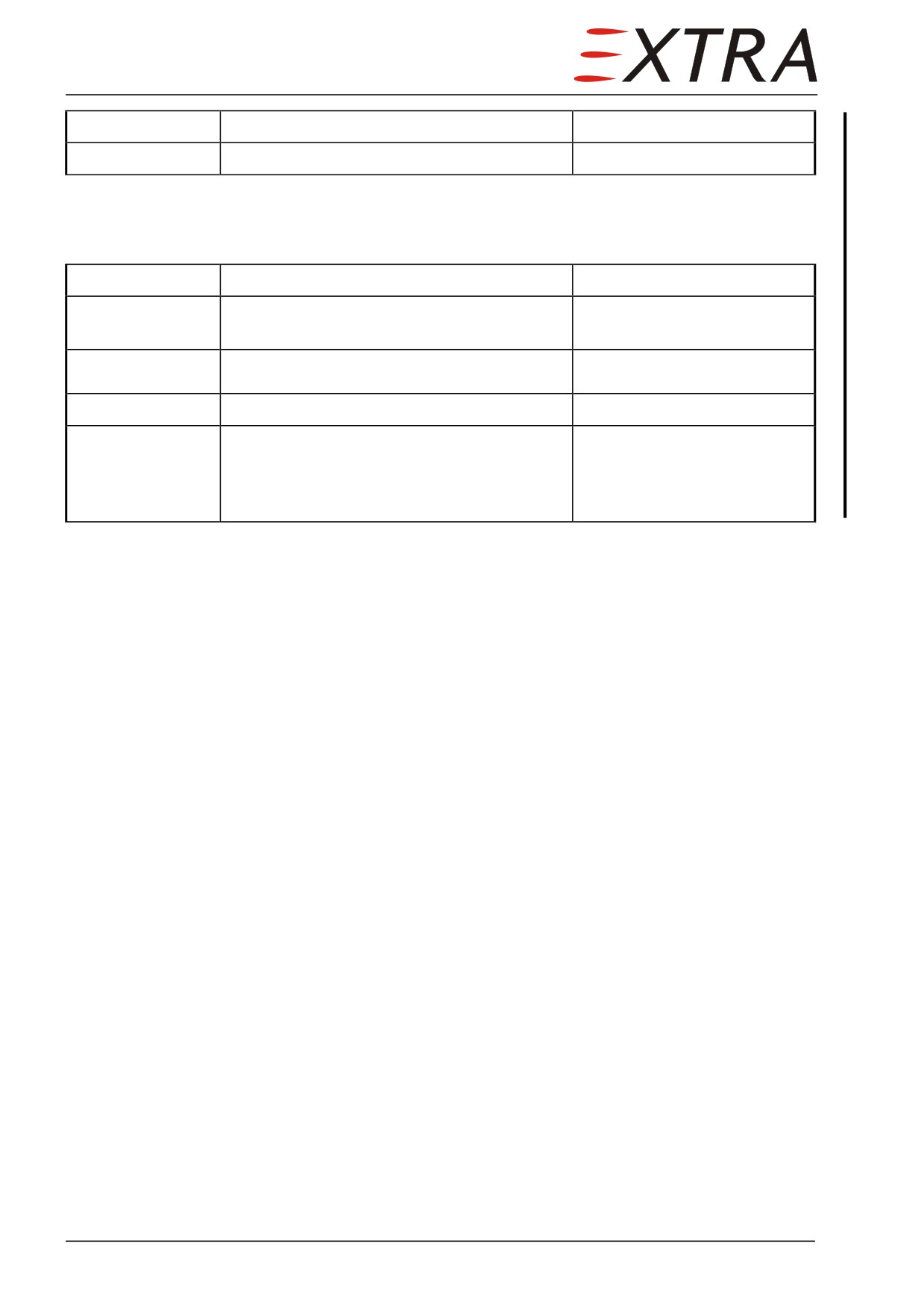
Detail Steps/Work Items
Key Items
5
Check springs (5/8) for general condition
Replace parts if necessary
Installation/Assembly
Refer to Figure 52-2
Detail Steps/Work Items
Key Items
1
Install/assemble in reverse sequence of
Observe the following items.
removal/disassembly
Clean all parts (incl. rod ends and ball joint
2
bearings) and mount with MIL-PRF-81322.
3
Glue in dowel pin (19) with Loctite 243.
4
When installing the inner guide pin (10) let
the related slotted spring pin (9) protrude
6 mm from the actuator (11) flange plane to
allow later removal.
Page 8 52
Page Date: 9. August 2013
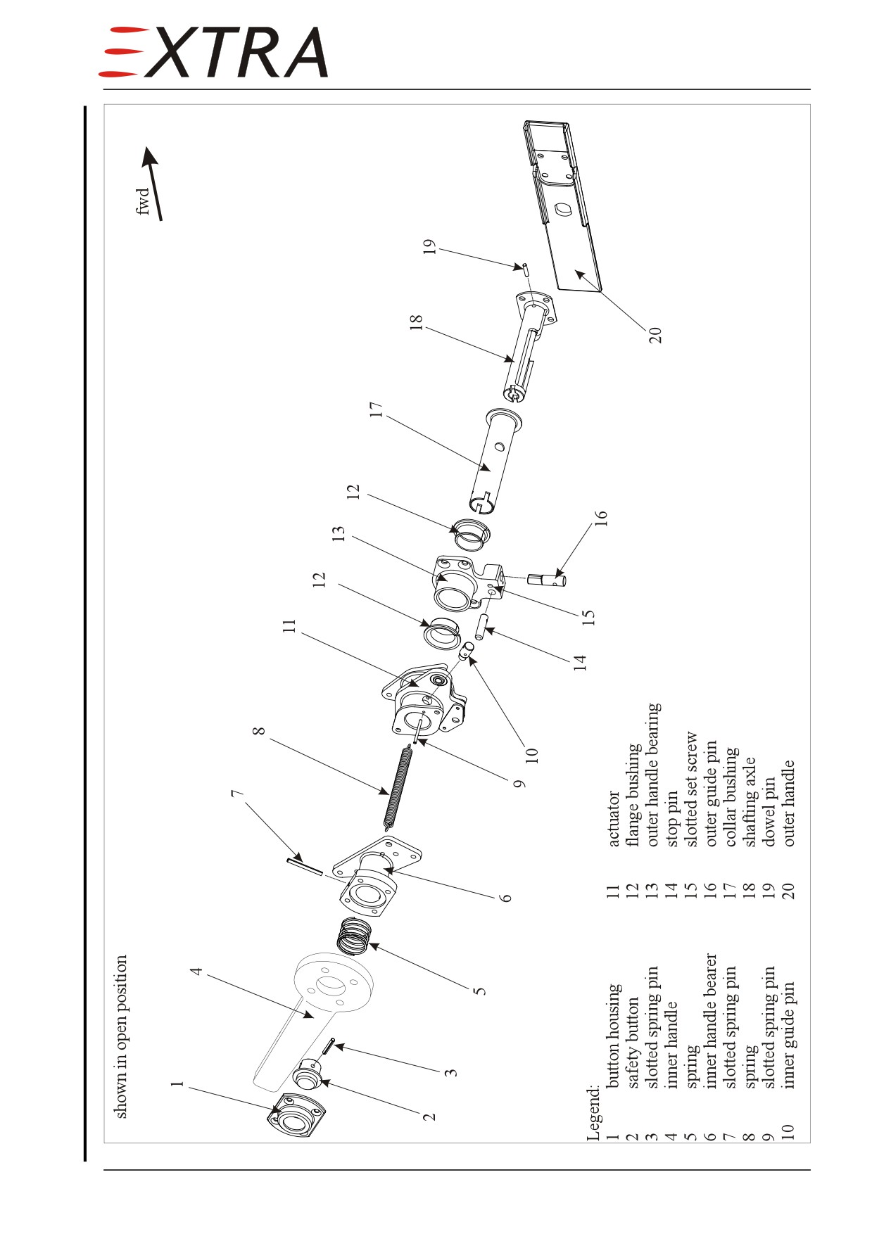
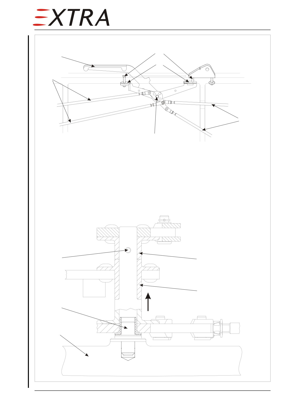
Figure 52-2
Central Door Operating Device
Page Date:
52 Page 9
52-10-04
Lower Door Operating Device
Removal/Disassembly
Refer to Figure 52-3
Detail Steps/Work Items
Key Items
1
Open lower door completely.
2
Remove handle from actuator lever
2 bolts
3
Remove the clamping strip.
Not arrested lower door could damage aircraft structure and lower door
CAUTION
hinges.
Support lower door at sufficient height, when removing the arresting
cables.
4
Disconnect arresting cables (7) from door
frame.
5
Remove the lower door paneling.
4 screws
6
Disconnect pushrods (1) from actuator (5).
7
Remove shims (4).
8
Lift actuator (5) from bearing bolt (7) and
remove, while guiding actuator lever
through the slot.
9
Disassemble actuator parts (9, 10) by
removing the slotted spring pin (8).
Inspection
Refer to Figure 52-3.
Replace 2.5 x 12 slotted spring pin (8) with 3 x 12 when play is detected.
Installation/Assembly
Detail Steps/Work Items
Key Items
1
Install/assemble in reverse sequence of
Observe the following item2.
removal/disassembly
Clean all parts (incl. rod ends and ball joint
2
bearings) and mount with MIL-PRF-81322.
Install 2 bolts of removal/disassembly with
3
Loctite 243
Page 10 52
Page Date: 9. August 2013
2
3
4
1
1
5
Legend:
1
pushrods
2
sill lever handle doubler
3
bolts
4
shims
5
actuator
6
lower door structure
7
bearing bolt
Actuator (5) Section Drawing
8
slotted spring pin
9
actuator, upper part
10 actuator, lower part
8
9
10
lift
7
6
Figure 52-3
Lower Door Operating Device
Page Date:
52 Page 11
52-10-05
Door Locking Mechanism
Refer to Figure 52-4
Disassembly/Assembly
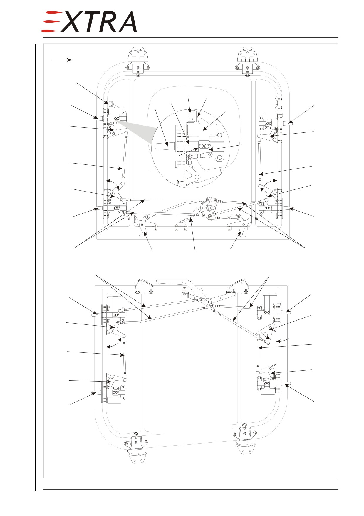
Disconnect the pushpull rods (2) from bellcranks (1) using standard practices.
Remove bellcranks (1), locking pin guidance (5), and door safety indicators (8)
by removing respective attaching bolts. Assemble in reverse sequence of
disassembly. Install safety wire where necessary.
Rigging
The general procedure begins with the respective door handle, which has to be
placed to the closed position. Then the following items have to be checked and
adjusted in the given sequence:
• bellcrank (1) installation angles
• gaps between locking pin linkage (9) and locking pin guidance (5)
• mounting of the door safety indicators (8)
• hook (4) position
Detail Steps/Work Items
Key Items
1
Close door from inside and check hooks (4)
Notice deviation from correct
lock completely. Check hole (5, Figure 52-
hook or safety indicator
1) must be visible. Check proper indication
position for later adjustment.
(green) of door safety indicators (8).
2
Remove door paneling.
Refer to Chapter 52-10-01/02
Damage to the door frame by the door locking pins (3) may occur, when
CAUTION
placing the door handle to the closed position and when moving the
door.
Observe the locking pins when working on the door.
3
Place upper door handle resp. sill lever to
If closed position cannot be
the closed position.
reached, adjust adjacent
pushrods.
4
Check gap between locking pin linkage (9,
If gap is detected, follow
Figure 52-4) and locking pin guidance (5) at
steps a and b.
all locking pins (3). No gap allowed.
a
Adjust pushrods to correct bellcrank (1)
Bellcrank angles on Figure
installation angles as per Figure 52-4, if
52-4 are given for the closed
applicable.
position.
b
Adjust pushrods (2) between bellcranks (1)
to minimize gap.
5
Check mounting of safety indicators (8).
Correct, if necessary
6
Adjust pushrods (2) to correct hook (4)
position, if necessary.
7
Reinstall door paneling.
Refer to Chapter 52-10-01/02
Page 12 52
Page Date: 9. August 2013
fwd
6
6
7
5
3
3
3
8
1
1
9
no gap
2
2
1
1
49°
64°
3
3
2
2
4
4
10
2
2
3
3
1
1
Legend:
13°
66.5°
1
bellcrank
2
2
2
push-pull rod
3
locking pin
4
hook
1
5
locking pin guidance
1
6
door switch
7
trigger sheet
8
safety indicator
3
3
9
locking pin linkage
10gas spring
Figure 52-4
Door Locking Mechanism
Page Date:
52 Page 13
52-10-06
Door Seal
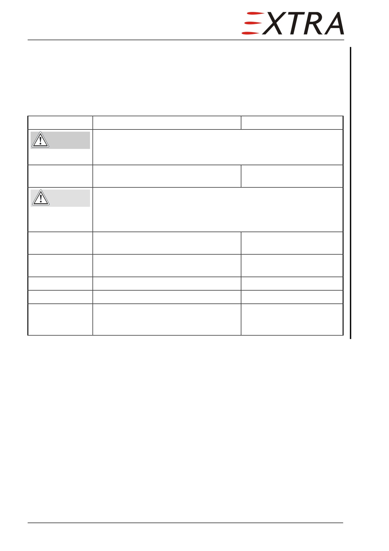
Up to serial number 1002 the cable of the door switch has to be disconnected
prior to removal of the door seal frame. Follow the Door Switch
Removal/Installation procedure as far as necessary to disconnect the cable.
Removal/Installation
Detail Steps/Work Items
Key Items
Not supported upper door could cause injuries by lodging.
WARNING
Let a helping person hold the upper door in open position.
Close upper door with care.
1
Disconnect telescopic (2, Figure 52-1) lift
cylinder from the door.
Not arrested lower door could damage aircraft structure and lower door
CAUTION
hinges.
Support lower door at sufficient height, when removing the arresting
cables.
2
Disconnect arresting cables (7, Figure 52-1)
from door frame.
3
Remove door threshold plate.
5 screws, hook-and-loop
fastener
4
Remove door seal frame.
34 screws
5
Remove door seal from frame.
Mark seal position on frame
6
Install in reverse sequence of removal.
Provisionally fix the seal to
the frame with tape. Remove
tape after frame installation.
Page 14 52
Page Date: 9. August 2013
52-10-07
Sill Seal
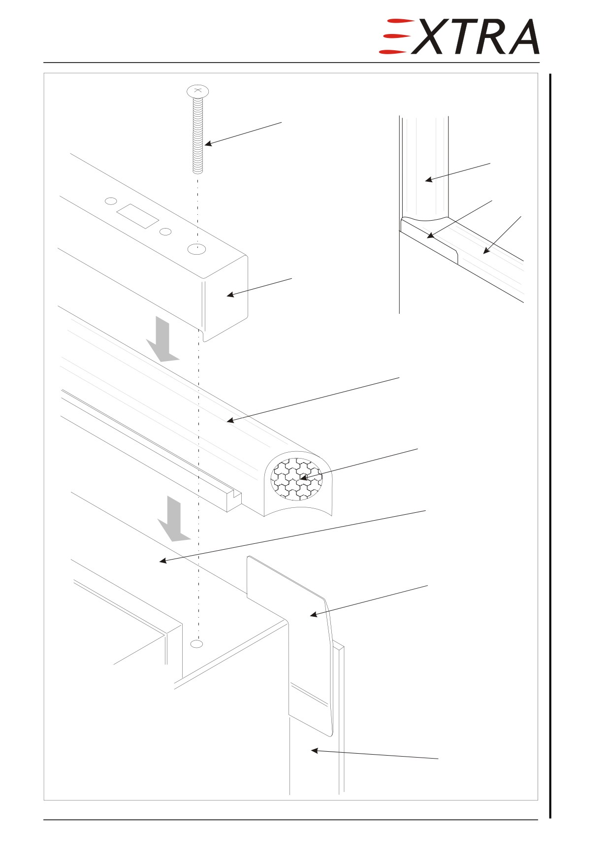
The gap between upper and lower door is sealed by means of the sill seal.
Removal
Refer to Figure 52-5.
Detail Steps/Work Items
Key Items
1
Open upper and lower door
2
Remove handle doubler (10, Figure 52-1)
from sill lever.
3
Remove sill seal frame (2, Figure 52-5).
5 bolts (1)
4
Remove sill seal (3) and corner seals (6).
Installation
Xdate
Refer to Figure 52-5.
Detail Steps/Work Items
Key Items
1
Cut the sill seal (3) to the shape and length
as outlined on Figure 52-5. Ensure that the
curve on the sill seal ends match the shape
of the door seal (8). Refer to Detail A.
2
Cut a foam rubber plug (4) of 35 mm length
Refer to Chapter 51-30-05
and glue into the ends of the sill seal (3).
Foam Rubber
Dow Corning 732. Follow the
instructions of the data and
safety sheet.
3
Place the sill seal (3) to the sill (5).
4
Install the sill seal frame (2).
5 bolts (1)
5
Clean the adherent surfaces of the corner
seals (6) with Aceton.
Glue the corner seals (6) on the door seam
6
Dow Corning 732. Follow the
(7) and on the sill seal (3).
instructions of the data and
safety sheet.
7
Install the handle doubler (10, Figure 52-1)
to the sill lever.
Page Date:9. August 2013
52 Page 15
Detail A
fwd
fwd
1
8
6
3
2
lower door shut
3
4
5
6
Legend:
1
bolt
2
sill seal frame
3
sill seal
4
foam rubber plug
5
sill
6
corner seal
7
7
door seam
8
door seal
Figure 52-5
Sill Seal
Page 16 52
Page Date:
52-10-08
Door Switch
The door switch (6, Figure 52-4) is located on the upper door next to the upper
left door safety indicator. Electrical connectors are located next to the switch
and/or under the upper side paneling.
Removal/Installation
Detail Steps/Work Items
Key Items
1
Remove upper door paneling.
Refer to Section 52-10-01
2
Disconnect wiring from door switch.
3
Remove the switch.
2 bolts
4
Install in reverse sequence of removal.
Adjustment
Detail Steps/Work Items
Key Items
1
Remove upper door paneling.
Refer to Section 52-10-01
2
Adjust the door switch (6) by bending the
The switch shall trigger
trigger sheet (7, Figure 52-4).
(“click”) just before the door
handle locks.
3
Reinstall upper door paneling.
Page Date:9. August 2013
52 Page 17