Extra 500. Maintenance Manual (2012) - page 8
27-00-00
GENERAL
Description
The flight controls consist of the ailerons, rudder and elevators. The right
elevator is equipped with a trim system. All these control surfaces are
constructed of composite material. The primary control system is a
conventional cable-system consisting of a double control wheel (pitch and roll)
with respective coupling systems, hanging control pedals (yaw), tubes, levers,
pulleys and push-pull rods. Between ailerons and rudder controls an
interconnection which is made via springs is installed. However, the coupling
can easily be overpowered (e.g. in side slipping).
27-00-01
Control Cable
Tensions
The control cable systems generally use cable of 3.2 mm diameter. However
the aileron control uses cables of 4 mm diameter in the wing region.
System
Cable Diameter
Cable Tension
Tolerance
Ailerons
3.2 mm/4 mm
220 N/49.5 lbs
20 N/4.5 lbs
Rudder
3.2 mm
220 N/49.5 lbs
20 N/4.5 lbs
Elevator
3.2 mm
300 N/67.4 lbs
20 N/4.5 lbs
27 Page 5
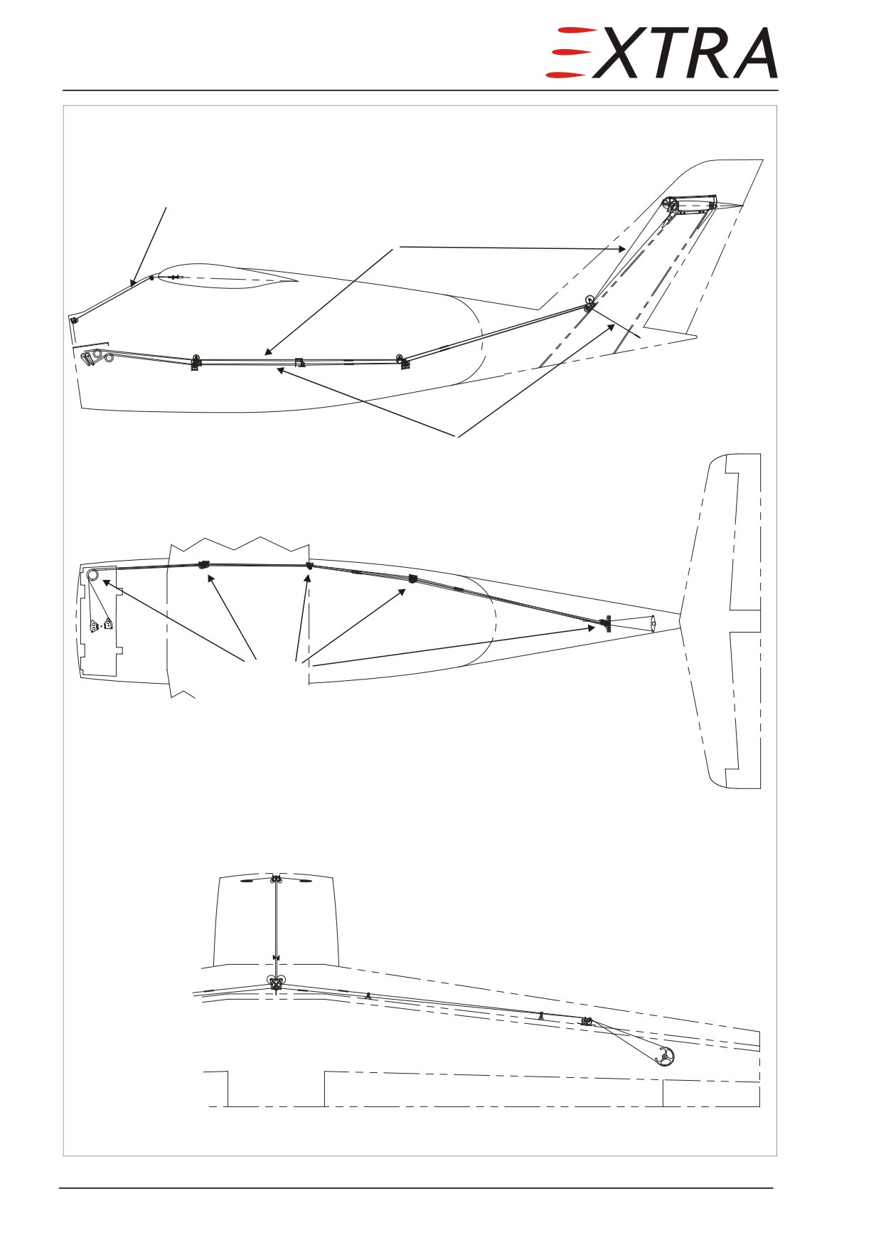
Side View
Pulley
Segment
Aileron Control
Elevator Control
Rudder Control
Top View
Turnbuckles
Pulleys
Rudder and Elevator
Control
Top View
Pulleys
Aileron Control
Pulley
Segment
Left Wing
symmetrically
Turnbuckles
Figure 27-01
Control System Surview
Page 6 27
27-00-10
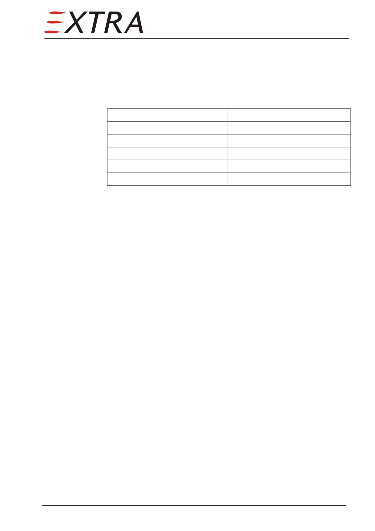
CONTROL SPRINGS
Location
The following springs are incorporated in the control system of the
EXTRA 500:
Application
Location
Down-spring
Cockpit, instrument shelf
Interconnection aileron/rudder
Cockpit, bulkhead
Centering rudder
Tail fairing
Nose gear steering
Nose wheel dome
Nose gear control cable
Cockpit
27-00-11
Down-Spring
Description
Safety spring, affecting the pulley segment of the elevator control, to create a
nose-down pitching control force. The down-spring is located on the LH side,
below the instrument shelf.
In case of down-spring failure the amount of steering force required will rise
when pushing the control yoke. Trimming "nose down" will compensate this
effect. Malfunction of the down-spring will not cause further reductions of
flight performance or any unsafe flight conditions.
27-00-12
Interconnection Aileron/Rudder
Description
To reduce tendency to raise the low wing, esp. during low speed flight (landing
approach), the EXTRA 500 is furnished with an interconnection between the
aileron and the rudder control. When activating the rudder, the coupling
correspondingly actuates the aileron control. When moving the aileron, the
rudder — as long as being free of any control forces — remains in neutral
position.
The coupling is being accomplished by means of a pair of safety springs,
located at the LH foot compartment. The control force is conducted from the
shafts of the rudder control to the safety springs by levers and cables, including
the pulleys.
Once the friction inside the control system has been overcome, a rudder control
input is led to the LH control column by a chain drive.
27 Page 7
Failure of an interconnection spring will cause an additional force in one
direction at the aileron control, which is rated below the tolerated amount.
27-00-13
Centering Rudder
Description
Within the lower rudder bearing a spring-loaded pulley strains a steel plate
attached to the rudder, thus centering the rudder in neutral position and
providing a defined rising of control forces while moving the rudder.
Malfunction of the centering spring will disengage the centering and reduce the
control force rise. Unsafe flight conditions are excluded.
27-00-14
Nose Gear Steering
Description
The pivoting of the nose gear is part of the rudder control system, completing
the control cable arrangement. To de-couple the nose gear steering from the
rudder control, two safety springs are incorporated into the nose gear pivoting.
The springs will transmit the control force forward after having reached a
defined travel.
Malfunction of the nose gear steering springs will abolish pretension of the
control cables. With a 16° play arising inside the nose gear steering, reduction
of max. angular movement from ± 30° to approx. 10° in one direction will
occur, whereas control force at the rudder pedals will slightly increase.
27-00-15
Nose Gear Control Cable
Description
These additional springs will stretch the nose gear control cables, when one of
the springs at the nose gear pivoting has been lengthened due to a rudder
movement against the locked nose wheel.
Malfunction of one or both springs will not affect normal control functions.
Page 8 27
27-10-00
AILERONS
Description
The coupling between the two control wheels of the main control system is
realized by a direct cable-chain coupling. The cables are connected to the
control wheels by means of a longitudinal toothed wheel and run through the
windshield center strut to the wing nose and move outboard. Outside the tank
area they cross the front spar. Then they are connected to a cable segment
which actuates the aileron via lever and push-rod.
Each aileron is attached to the rear spar of the wing by two hinges.
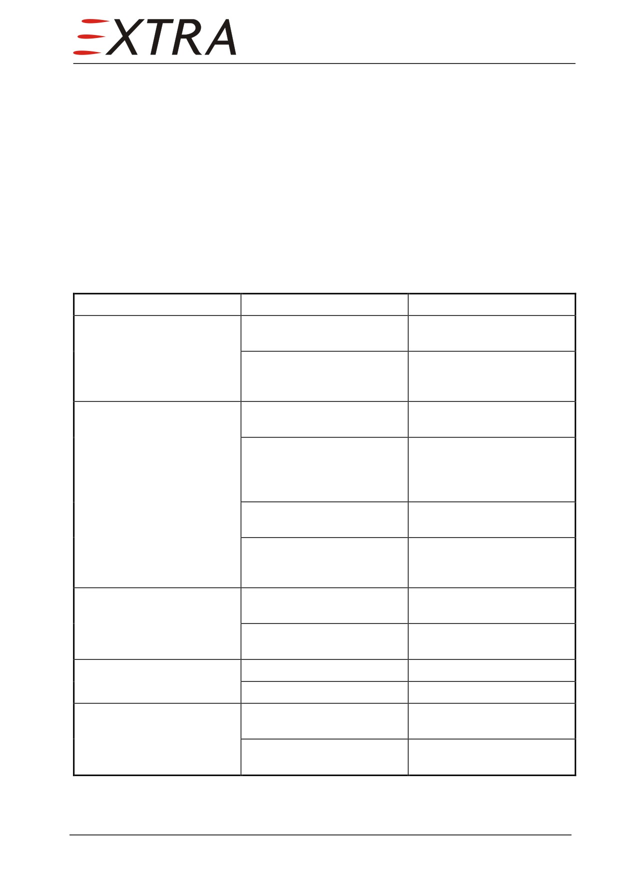
Troubleshooting
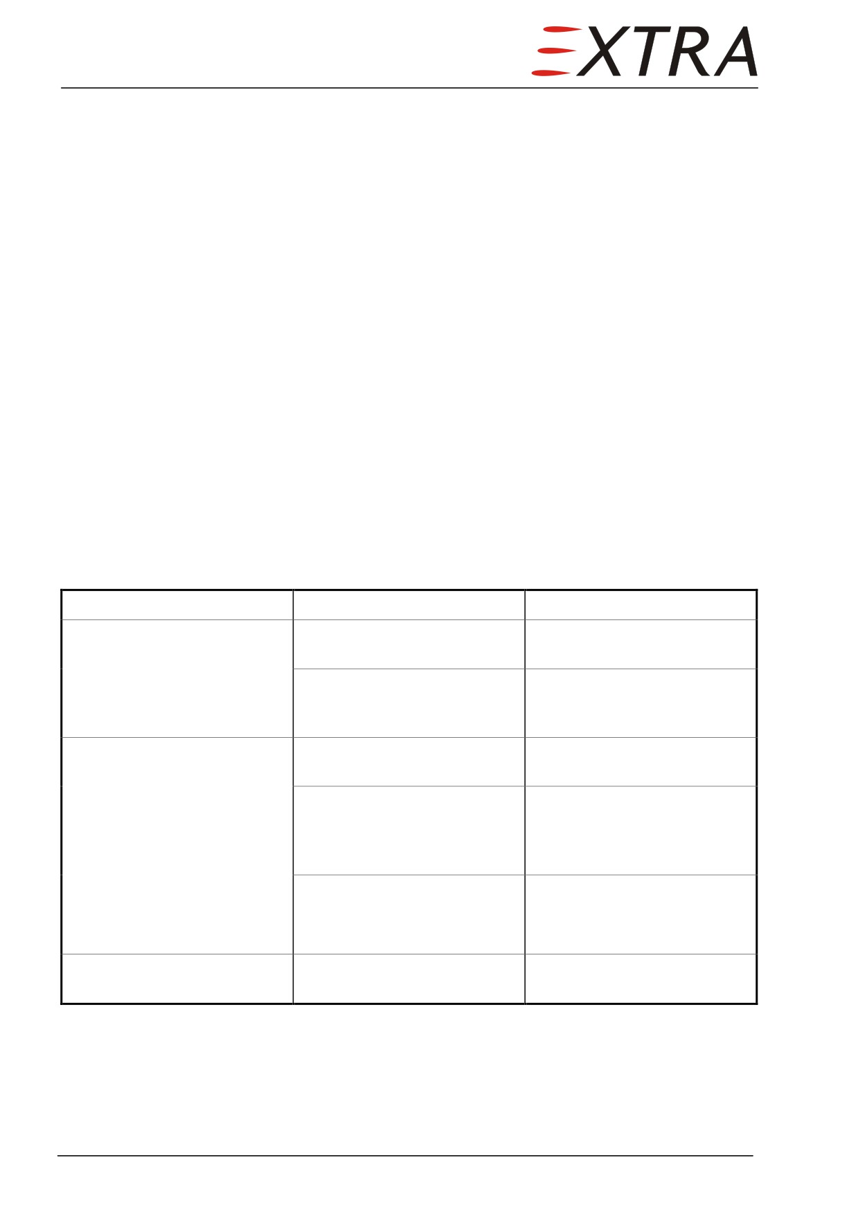
Complaint
Possible Cause
Remedy
Lost motion in control wheel.
Loose control cables.
Check cable tension. Adjust
cables to proper tension.
Broken pulley or braket, cable
Check visually. Replace worn
of pulley or worn rod end
or broken parts, install cables
bearings.
correctly.
Resistance to control wheel
Cables too tight.
Check cable tension. Adjust
movement.
cables to proper tension.
Pulleys binding or cable off.
Observe motion of the pulleys.
Check cables visually. Replace
defective pulleys. Install
cables correctly.
Defective quadrant assembly.
Check visually. Replace
defective quadrant.
Clevis bolts in system too
Check connections where
tight.
used. Loosen, then tighten
properly and safety.
Control wheels not level with
Improper adjustment of cables.
Adjust turnbuckle to obtain
ailerons neutral
proper alignment.
Improper adjustment of
Adjust push-pull rods to obtain
aileron push-pull rods.
proper alignment.
Dual control wheels not
Cables improperly adjusted.
Adjust cables.
coordinated.
Chain improperly adjusted.
Adjust chain.
Incorrect aileron travel.
Push-pull rod not adjusted
Adjust rod.
properly.
Incorrect adjustment of travel
Adjust bolts.
stop bolts.
27 Page 9
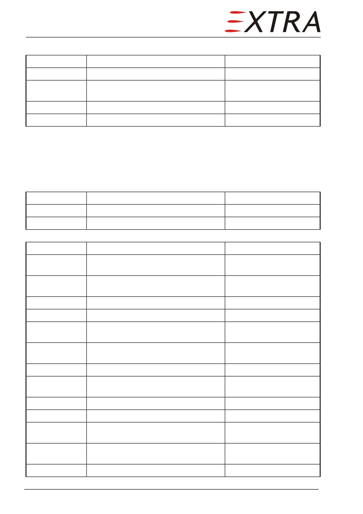
Removal/Installation
Detail Steps/Work Items
Key Items
1
Loosen push rod from central part of aileron
2
Remove cotter pin and bolt from each of the
two hinges
3
Remove aileron backwards
4
Install in reverse order of removal
27-10-01
Aileron Cables
Removal/Installation
Detail Steps/Work Items
Key Items
1
Remove center cover of wing root section
2
Remove turnbuckle below cover
Perform steps No 3 - 9 at LH and RH side wing each
3
Remove turnbuckle at outer wing rib
4
Remove rigging clamps of role servo at
inner wing rib
5
Remove recognition light at outer wing nose
section
6
Remove outer side pulley
7
Push up inner side pulley
8
Remove teflon guiding bushings at outer
wing rib
9
Loosen return cable segment at outer wing
Remove bolt and push
rib for removal of 3.6 mm cable
segment sideways
10
Remove 2 pulleys at windshield center strut
11
Remove teflon guiding bushings at
windshield center strut
12
Remove avionic panel
13
Remove LH and RH side return brackets
14
Remove LH and RH cable safety brackets
below instrument shelf
15
Loosen return cable segments at steering
Remove bolts and push
column
segments sideways
16
Install in reverse order of removal
Page 10 27
27-20-00
RUDDER
Description
The rudder pedals are placed hanging on two tubes which have a lever arm at
the right side of the cabin. From there the cables are led along the cabin right
side armrest panel to the empennage around pulleys positioned in groups. Here
a direct connection to the lever arms of the rudder follows. The connection
points lay inside the tail cone adjacent to the lower rudder bearing.
The rudder is connected to the rear fin spar at three points.
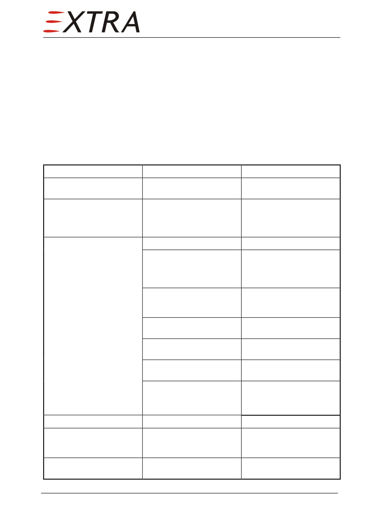
Troubleshooting
Complaint
Possible Cause
Remedy
Play between pedals and
Insufficient cable tension.
Rig the system.
rudder.
Rudder does not respond to
Broken or disconnected
Open armrest panel, access
pedal movement.
cables.
doors and tailcone and check
visually. Connect or replace
cables.
Excessive resistance against
Cables too tight.
Rig the system.
pedal movement, binding or
Cables not running properly
Open armrest panel, access
jumpy movement of pedals.
on pulleys.
doors and tailcone and check
visually. Lay cables correctly
over pulleys.
Binding, broken or defective
Check visually. Replace
pulleys or cable guards.
defective pulleys and install
guards properly.
Pedal torque-tube bearings
Lubricate pedal bearings.
need lubrication.
Defective pedal torque-tube
Check visually. Replace
bearings.
bearings.
Defective rudder hinge
Check visually. Replace
bearings.
defective bearings.
Clevis bolts too tight.
Check and readjust bolts to
eliminate binding.
Incorrect rudder travel.
Incorrect rigging.
Rig the system.
Excessive resistance against
Worn or defective nosewheel
Check visually. Replace
pedal movement only while
steering bearings
defective bearings.
gear is extended
Nosewheel does not respond
Broken or disconnected
Check visually. Connect or
to pedal movement.
cables.
replace cables.
27 Page 11
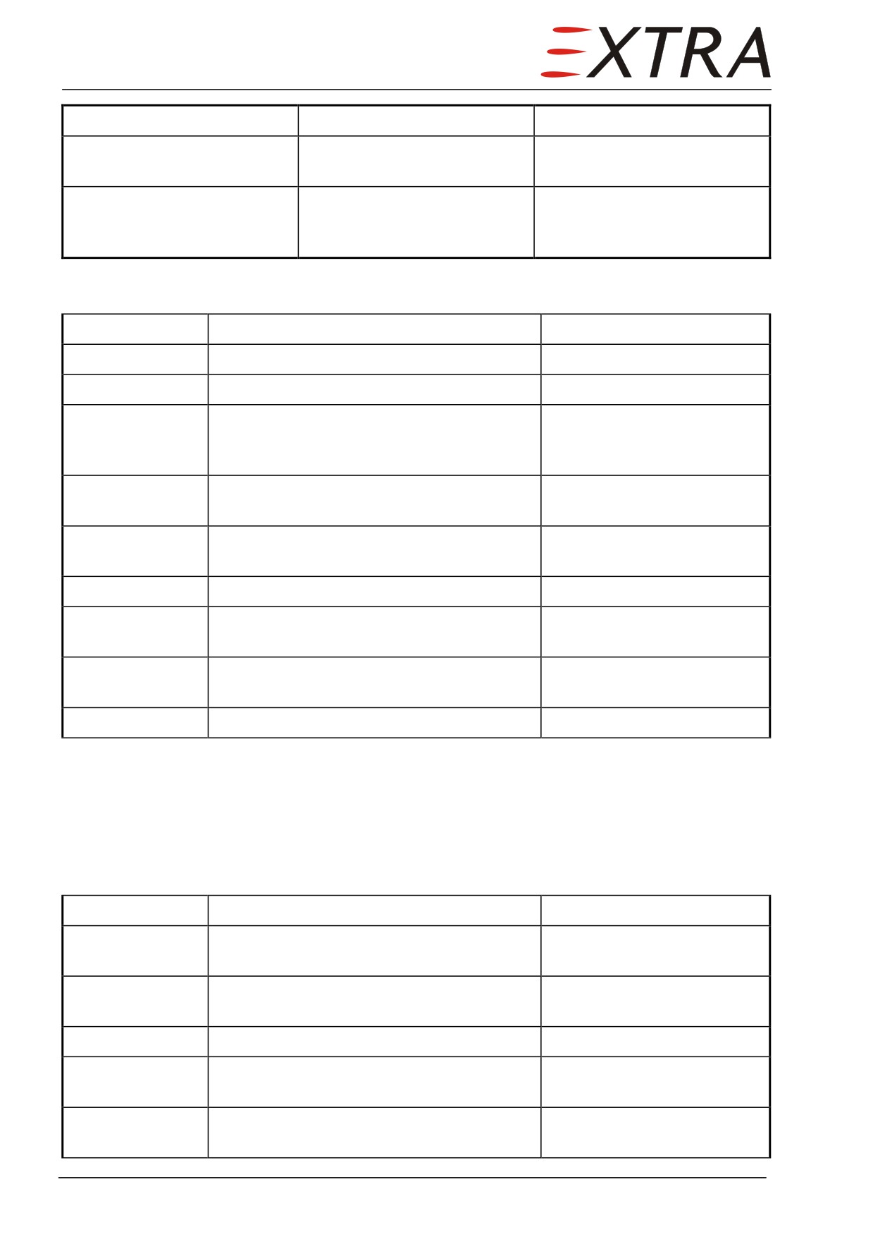
Complaint
Possible Cause
Remedy
Reduced nosewheel steering
One steering cable spring
Check visually. Replace spring
travel on one side
broken
Incorrect nosewheel steering
Incorrect rigging.
Rig the system.
travel / aircraft not rolling
straightly with pedals neutral.
Removal/Installation
Detail Steps/Work Items
Key Items
1
Remove right aft passenger seat
Refer to Chapter 25-20-13
2
Remove RH side paneling
Refer to Chapter 25-20-22
3
Loosen two turnbuckles of rudder cables,
located at RH wall adjacent to right aft seat
and baggage compartment
4
Loosen rudder cables at lower rudder
bearing
5
Remove bolt at LH side of central rudder
bearing
6
Remove lower rudder bearing
5 screws M5
7
Remove cotter pin and nut at lower rudder
bearing
8
Slightly lift rudder above higher bearing and
remove rudder backwards
9
Install in reverse order of removal
27-20-01
Rudder Cables
Removal/Installation
Detail Steps/Work Items
Key Items
1
Remove lower RH side panels in flight,
passenger and baggage compartments
2
Remove upper rear wall of baggage
compartment
3
Remove instrument shelf
4
Remove turnbuckle below RH side of
instrument shelf
5
Remove 2 turnbuckles at RH side wall in
baggage compartment
Page 12 27
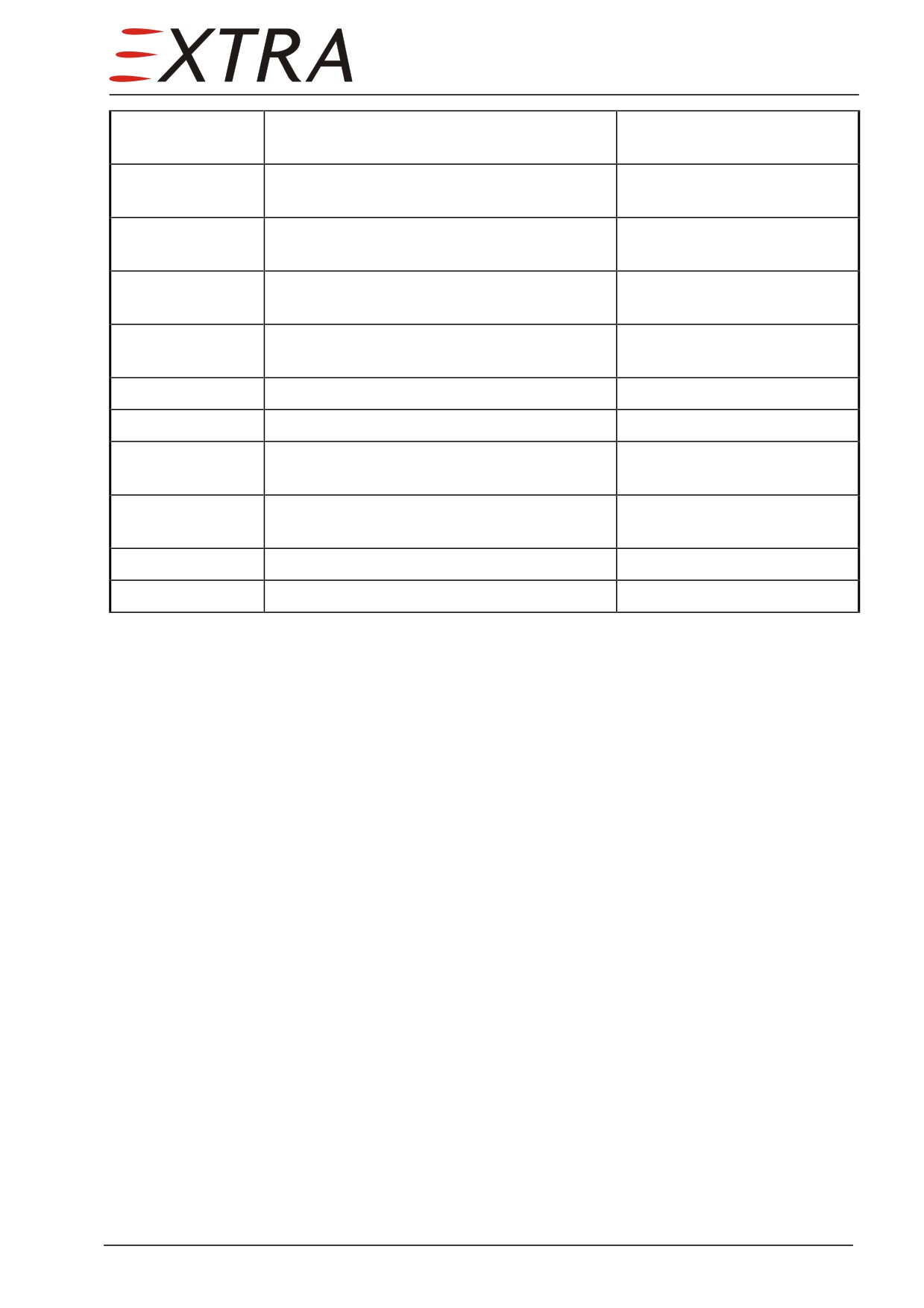
6
Remove turnbuckle at rear wall of baggage
compartment
7
Remove 2 pulleys below instrument shelf
Remove safety pin from
smaller pulley
8
Remove 2 pulleys from RH side wall in
Remove bolts
flight compartment
9
Remove 2 pulleys from RH side wall in rear
Remove bolts
passenger compartment
10
Remove teflon guiding bushings at rear wall
of baggage compartment
11
Remove LH access panel at rear fin
12
Remove 2 smaller pulleys
13
Remove 2 pulleys at LH and RH side each
below instrument shelf
14
Remove teflon guiding bushings to nose
Remove safety sheet
wheel well
15
Remove nose gear cable control springs
16
Install in reverse order of removal
27 Page 13
27-30-00
ELEVATOR AND TAB
Description
A lever system transfers elevator control movement from each of the two
steering wheels by a respective carrier bolt bushing to a cable segment. From
this cable segment the elevator cables run horizontally to the right cabin side to
a 90° pulley and parallel to the rudder cables to the empennage. They are led to
the elevator in front of the front fin spar and are attached to a lever positioned
in front of the horizontal stabilizer front spar, which actuates the two elevator
sides separately by means of push pull rods. Each elevator is attached to the
respective horizontal stabilizer by three bearings.
The mechanical pitch trim is actuated through a trim wheel in the pedestal. The
pitch trim tab is located in the right elevator and is linked over a 'redundant'
cable-lever system to the trim wheel. The trim Bowden cables run from the
middle console down crossing the cabin floor and are then directed rearwards
to the empennage following the nose section of the fin to the right side
elevator. Pitch trim can be actuated electrically also by means of switches
located on the pilot's control wheel. The system can be overpowered by pilot's
hand forces in case of system failure.
Troubleshooting
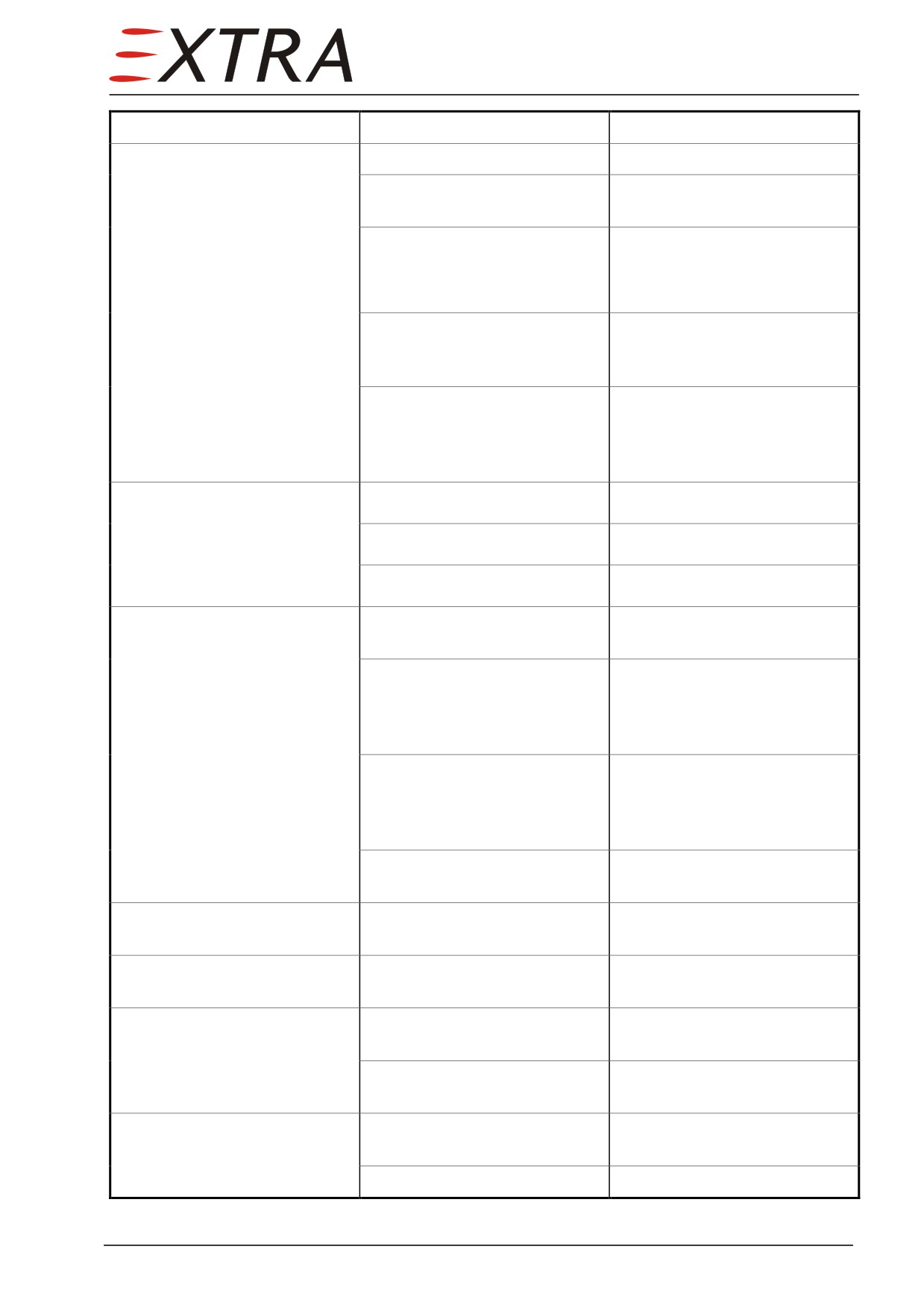
Complaint
Possible Cause
Remedy
Play in control column.
Loose control cables.
Check cable tension. Adjust
cables to proper tension.
Broken pulley or bracket,
Check visually. Replace worn
cable off pulley, or worn rod
or broken parts, install cables
end bearings.
correctly.
Excessive resistance to control
Cables too tight.
Check cable tension. Adjust
column movement.
cables to proper tension.
Pulleys binding or cable off.
Observe motion of the pulleys.
Check cables visually. Replace
defective pulleys. Install
cables correctly.
Defective pulley quadrant
Check visually. Replace
assembly.
defective quadrant.
No nose down force on control
Down-spring disconnected.
Check visually. Attach down-
column.
spring correctly.
Page 14 27
Complaint
Possible Cause
Remedy
Binding or jumpy motion felt
Cables too tight.
Check and adjust tension.
in movement of elevator
Cables not riding correctly on
Check visually. Replace
system.
pulleys.
defective pulleys.
Defective control column
Check visually. Replace
bearings.
defective bearings.
Control guide on aft end of
Loosen screw and tapered plug
control square tube adjusted
in end of control tube enough
too tightly.
to eliminate binding.
Defective elevator hinges.
Disconnect push-pull rods and
move elevators by hand.
Replace defective hinge
bearings.
Elevator fails to attain
Stops set incorrectly.
Rig the system.
prescribed travel.
Cables tightened unevenly.
Rig the system.
Trim control wheel moves
Defective cable or deformed
Check visually and replace
with excessive resistance.
tube.
defective parts.
Trim tab hinge binding.
Disconnect actuator and move
tab up and down to check
hinge resistance. Lubricate or
replace hinge as necessary.
Defective trim tab actuator.
Disconnect cable from
actuator and operate actuator
manually. Replace defective
actuator.
Stick-slip effect between cable
Lubricate all moving parts.
and tube.
Control wheel does not move
Disconnected or broken cable.
Check visually and connect or
trim tab.
replace cable as necessary.
Play between control wheel
Parts worn out
Check visually and replace
and trim tab.
parts as necessary.
False reading on trim position
Indicator incorrectly engaged
Check visually. Adjust
indicator.
on wheel axis.
indicator.
Worn, bent or disconnected
Check visually. Repair or
linkage.
replace parts as necessary.
Incorrect trim tab travel.
Stop blocks loose or
Adjust stop blocks on cables.
incorrectly adjusted.
Incorrect rigging.
Rig the system.
27 Page 15
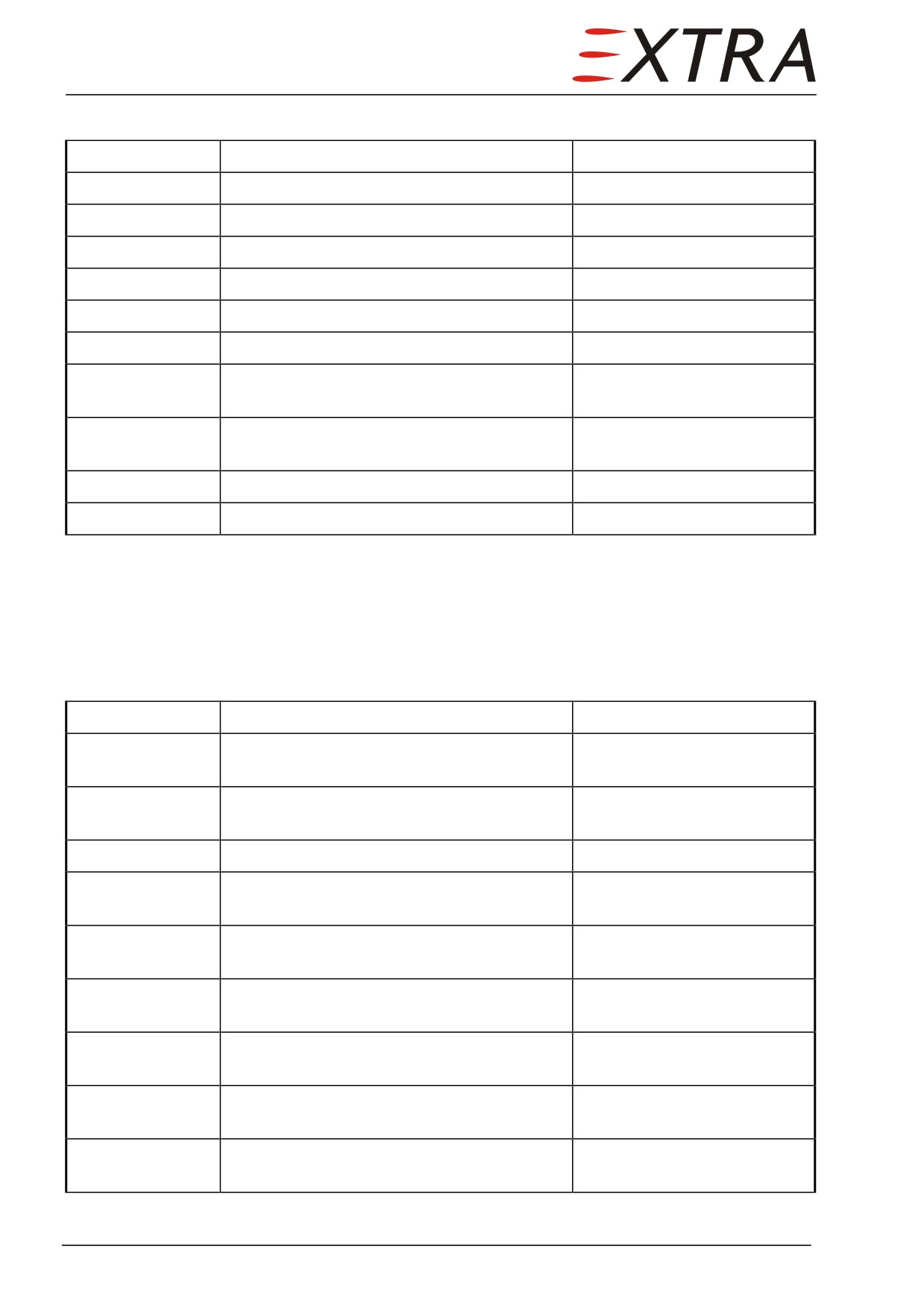
Removal/Installation
Detail Steps/Work Items
Key Items
RH elevator
1
Loosen push rod at trimming tab
8 hollow core bolts LN4
2
Continue as per step 1 to 5, LH elevator
LH elevator
1
Loosen control lever
2
Swivel up elevator
3
Remove socket pins from central and outer
2 socket pins LN6
bearings
4
Turn elevator horizontally backwards
around inner bearing
5
Remove elevator
6
Install in reverse order of removal
27-30-01
Elevator Cables
Removal/Installation
Detail Steps/Work Items
Key Items
1
Remove lower RH side panels in flight,
passenger and baggage compartments
2
Remove upper rear wall of baggage
compartment
3
Remove instrument shelf
4
Remove turnbuckle below RH side of
instrument shelf
5
Remove 2 turnbuckles at RH side wall in
baggage compartment
6
Remove turnbuckle at rear wall of baggage
compartment
7
Remove 2 pulleys below instrument shelf
Remove safety pin from
smaller pulley
8
Remove 2 pulleys from RH side wall in
Remove bolts
flight compartment
9
Remove 2 pulleys from RH side wall in rear
Remove bolts
passenger compartment
Page 16 27
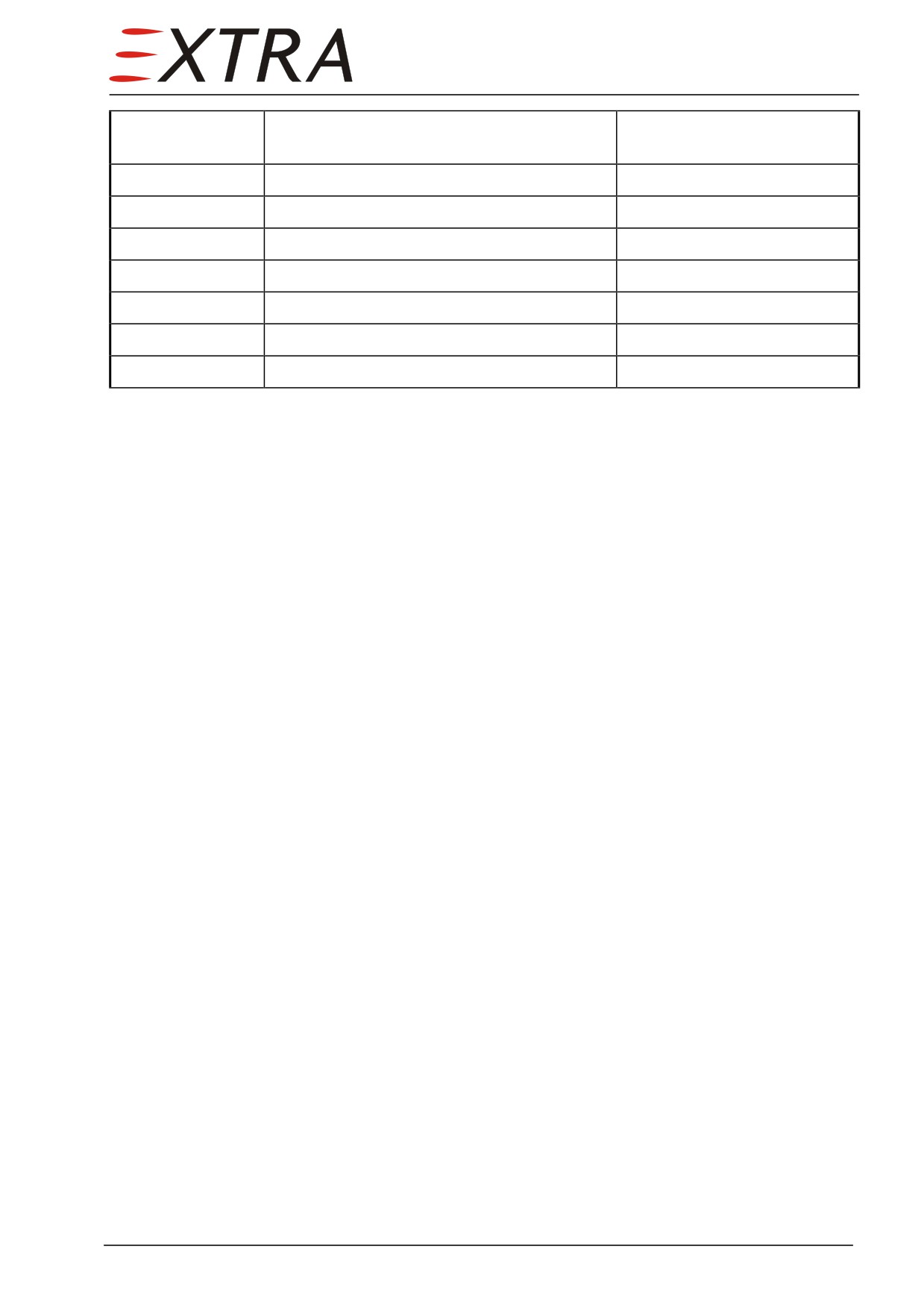
10
Remove teflon guiding bushings at rear wall
of baggage compartment
11
Remove LH tailcone access panel
12
Remove 2 clamps of pitch servo
13
Remove LH access panel at rear fin
14
Remove 2 larger pulleys
15
Remove linkage between cable and aileron
Remove bolt
16
Remove push rod
17
Install in reverse order of removal
27 Page 17
27-50-00
FLAP SYSTEM
Description
The wing flaps are of the Fowler type. Each wing flap (two per side) is
attached to the rear wing spar and guided during its movement by three wing
tracks. Actuation is by means of two spindles, which are connected to the
central electrical flap motor by flexible shafts. The flap motor is located in
front of the rear spar in the fuselage area of the wing and is controlled by the
wing flap position switch in the cockpit. This switch incorporates a preselect
feature which allows the pilot to select the amount of flap extension desired.
When the UP/0°- , 15°- or
30°- position is selected, the flap motor is
electrically actuated and drives the flaps toward the selected position. When the
actual flap position equals the selected position, limit switches located at the
wing tracks respective the outer spindles de-energize the flap motor. The actual
flap position will be indicated by green lights at the left side of the wing flap
position switch. When flaps are moving the yellow light will be illuminated. If
the 0°-position is reached all lights are off.
As the flaps move an electrical circuit compares the movement of the left and
right wing flaps. If the wing flap positions differ by more than 7° ± 3°, the flap
motor will be automatically switched off to prevent asymmetric conditions.
This will be indicated by the flap error warning light located on the warning
light panel. This light indicates also a failure of the complete flap control.
NOTE
In case of the wing flaps being unbalanced, they rest in the position they
have reached when failing and cannot be actuated until airplane has been
in maintenance. However in this case the airplane can be easily balanced
by slight aileron and/or rudder input.
Setting the wing flaps will cause a decrease of airspeed and a moderate nose
down moment.
Bring wing flaps to 0°-position before opening the cabin door
CAUTION
Rigging and Adjustment
This section describes the procedure for correct adjustment of the defined flap
settings as well as the maximum flap asymmetric limits.
Due to the local chord of the flaps (30 % of the wing) and positioning the 15°
and 30° DOWN extension relative to the local chord the travel of the flaps
depends on the lateral station.
All adjustment must be made with the motor power OFF (pulled circuit
CAUTION
breaker FLAP).
NOTE
Rigging of the flap system requires a flap track snap gauge (Extra Part-
No. EA-15182W10). This will be available at EXTRA. See also Chapter
01-00-02.
Page 18 27
Track Adjustment
Perform the following adjustment checks as long as the flaps are not installed.
For flap installation, refer to Chapter 57-50-01:
1
Check of spanwise adjustment
Check distance between flap tracks at their rear end. Distance between inner
and middle track is 1989 ± 2 mm (78.31 ± 0.08 in.) and between middle and
outer track 1827.5 ± 2 mm (71.95 ± 0.08 in.). If further details of flap track
positioning are required, contact EXTRA.
2
Check of twist between tracks
Check flap tracks for proper torsional alignment (cord over all three lower
keyways). Max. permissible distance of lower keyway centerline at the middle
flap track is 2mm (0.08 in.), when cord is aligned with outer and inner flap
track keyway.
Guidance Checks and Adjustment
Check the following items after flap installation:
1
Minimum gap between flap and aileron
While pulling the flaps outboard against the stop, check width of gap between
aileron and outer flap segment. The stop is reached, when one of the sliding
surfaces on the outboard end of the inner or outer flap segment contacts the
middle or outer flap track. Minimum gap width is 8 mm (0.31 in.).
Check the following items after flap installation and after each 100 hours of
operation:
2
Spanwise flap rigging
Check whether any guidance roller on the inner track protrudes more than
3 mm (0.12 in.) outside the inner track when flaps are pulled outboard against
the stop. The stop is reached, when one of the sliding surfaces on the outboard
end of the inner or outer flap segment contacts the middle or outer flap track.
Repeat the check for the rollers in the outer flap track while pushing the flaps
inboard. Verify visually that stops are definitely reached.
3
Flap guidance rollers twist rigging
Minimum play in guidance keyways: Check all flap segments for minimum
free play of rollers in keyways. Lift each flap segment manually at trailing edge
and observe for positive free play of flap segment at trailing edge. Check this
for all four flap segments and for flap positions 0° and 30°. The SKF track
rollers (forward roller on inner track and both rollers on outer track) feature an
eccentric bushing to provide a means of adjustment in this respect.
4
Flap guidance rollers functional check
Check whether the rollers are rolling but not slipping by performing the
following test: Extend flaps to their
30° position and retract them while
manually applying a load of about 200 N (45.0 lbs.) upwards at the trailing
edge of the flaps near the respective track. If a roller is slipping identify cause
and replace roller as necessary.
27 Page 19
5
Inspection of roller contact areas
Inspect rear side of lower keyway on inner flap tracks for signs of axial contact
with mushroom head of roller. Contact Extra Flugzeugbau GmbH if marks are
found.
Inspect guidance roller tracks for wear and permanent deformation.
For wear and deformation the following service limits are defined:
Max. increase of track width due to deformation: 0.6 mm (0.024 in.) per side.
Width of guidance slot between 16.3 mm and 16.8 mm (0.64 in. and 0.66 in.).
Check with flap track snap gauge (see Chapter 01-00-02).
Actuation Adjustment
1
Ascertain that both inner flex drive shafts are disconnected from the electric
drive motor and that the flap motor and flap control circuit breakers are pulled.
2
Make sure for both LH and RH side flap that the respective asymmetry
detection mechanisms are not mounted yet. If they are already mounted, make
sure that the ball joint connection between linkage rod and bracket is
disconnected and the linkage rod is taped to the spar.
If this is not done, parts of the mechanism may be destroyed while
CAUTION
moving the flaps.
3
Lower both (LH and RH) flaps to their fully extended stop position. This can
be done by turning the hex socket coupling of the RH flex shaft CCW and the
LH flex shaft CW respectively, with view of the coupling. Use a battery hand
held drill with fine speed control and reverse feature, equipped with a 3/16 “
(4.7 mm) Allen key tip.
Do not run flaps to their extreme position (end of trackslots) with electric
CAUTION
drill to avoid damage. Turn flex shafts by hand to reach the end of the
tracks.
4
If the roller on one flap end rib reaches the outer end of its track slot while the
roller on the other flap end rib is 2 mm or more away from its track slot end,
an adjustment is necessary. This is done at one of the two transmission screw
jacks.
5
Disconnect the flap bracket from the rod end of its transmission actuator, then
move the rod into the proper direction by rotating it in steps of 180°-turns,
then reconnect. A 180°-turn of the inner transmission’s rod in CCW direction
or of the outer transmission’s rod in CW direction will move the adjacent
roller about 2 mm towards the extended position.
NOTE
The screw of the inboard transmission rod features a RH thread whereas
the outboard one features a LH thread
6
Raise both (LH and RH) flaps from their extended stop positions by rotating
the hex socket coupling of the flex drive shafts 2.5 turns in reverse direction to
secure a gap between rollers and track slot ends about 1.5 mm (.06"). This will
give the 30° position. Use a 3/16" (4.7 mm) Allen key and turn by hand.
7
The basic adjustment dimensions at the transmission actuators (measured from
the center of the mounting pin of the screw jack to the center of the rod end)
are:
Page 20 27
Position
0° Retracted
15° Intermediate
30° Extended
Inner actuator
58 + 3/- 0 mm
152 + 3/- 0 mm
270 + 3/- 0 mm
2.28 + .12/-0 inches
5.98 + .12/-0 inches
10.63+ .12/-0 inches
Outer actuator
68 + 3/- 0 mm
135 + 3/- 0 mm
219 + 3/- 0 mm
2.68 + .12/-0 inches
5.31 + .12/-0 inches
8.62 + .12/-0 inches
8 If the rod end at the transmission screw and the respective flap bracket do not
align, disconnect the rod end from the bracket and loosen the two bolts
securing the bracket to the flap. This will allow the bracket to be moved by
tapping. Connect the rod end to the bracket and tap the bracket to achieve a
satisfactory alignment. Disconnect the rod end from the bracket and torque the
bracket attachment bolts. With the transmission screw and flap bracket
aligned, finally connect the rod end to the bracket with the bolt assy.
9 When measuring flap deflection angles, lift the trailing edge of the flap to
eliminate play between rollers and track slots.
27-50-01
Flap Drive Motor
Description
Brush type bidirectional permanent magnet motor, positioned in the wing
center box at the front web of the rear spar
Characteristics:
1
Hex shafts on both sides
2
Capability of dynamic braking
3
Max. ambient temperature: + 40 °C
4
Voltage: 24 to 30 VDC, 24 VDC nominal
5
Torque at output shaft: 50.7 Ncm nominal at 24 VDC, 1,600 RPM, 4.5 amps
6
Power output: 85 W
7
Ratio RPM/Torque: 5.1 (Ncm ⋅ min) -1
8
Voltage factor: 0.013 V ⋅ min
9
Efficiency: 78 %
10
Insulation class IP 54 according DIN 40050 (protected against dirt, dust and
ingressed water)
27 Page 21
27-50-02
Inboard Power Transmission Flexible Shaft
Description
The inboard flexible shaft has a female 3/16" hex drive at motor side and a
DIN 75532 E1 for the screw jack side. LH and RH flex shaft are different in
main rotation due to the musk wire: CW or CCW for main rotation.
Characteristics:
1 Length: 1,400 mm
2 Core: Carbon steel musk wire φ 6 mm
3 Casing and end fittings in CRES
4 Shrink sleeve on casing
5 Minimum installation bend radius: 300 mm
6 Coupling nut 2024-T4 blue anodized or CRES with hole for safety wire
7 Min. static torque : 300 Ncm
27-50-03
Outboard Power Transmission Flexible Shaft
Description
The outboard flexible shaft is a standard type DIN 75532 E1. As for the
inboard shaft LH and RH flex shafts are different in main rotation due to the
musk wire: CW or CCW for main rotation.
Characteristics:
1 Length: 2,000 mm
2 Core: Carbon steel musk wire φ 4 mm
3 Steel casing
4 End fitting in steel zinc - plated galvanically
5 Shrink sleeve on casing
6 Minimum installation bend radius: 55 mm
7 Coupling nut aluminium with hole for safety wire
8 Min. static torque: RH 104 Ncm (CCW)/49 Ncm (CW)
LH 104 Ncm (CW)/49 Ncm (CCW)
Page 22 27
27-50-04
Power Transmission Screw Jacks
Description
The in- an outboard screw jacks consists of a reduction worm gear and
machine screw nut with trapezoid thread (irreversible by choice of pitch). The
inboard screw jacks have right hand threads, the outboard screw jacks left hand
threads. The worm shaft and the screw nut are equipped with ball bearings.
Characteristics:
1
Worm gear ratio: inboard 5:1
outboard 7:1
2
Efficiency of worm gear: inboard 0.7
outboard 0.65
3
Pitch of screw nut: 3 mm stroke per revolution
4
Number of revolutions for full stroke of screw jack (30° flap setting):
inboard 70 revolutions
outboard 50 revolutions
5
Stopping accuracy: ± 3 % of full stroke
6
The unit is sealed
7
All external parts are protected against corrosion
8
Periodic lubrication is not required
9
Output shaft splines: According DIN 75532 E2 for connection to the flexible
drive shafts
27-50-05
Flap Control Box
Description
A Flap Control Box providing the flap control functions is fixed into the
avionic bay with an adapted bracket, using 4 AN bolts with AN washers.
The Flap Control Box performs the following functions:
1 Controlling the motor for the 3 intended flap - positions (retracted, 15° inter-
mediate and 30° fully extended)
2 Activating the flap position signals 15°, 30° or "flaps in transition"
and:
Asymmetry detection by controlling the rheostats fitted at the outboard flaps
on the LH and RH, thus activating:
1 Motor shut-off
2 Signalisation to the warning panel inside the cockpit
Wing flap asymmetric tolerances are adjustable at the trimmer of the watchdog
box. Refer to Subject 27-50-07.
27 Page 23
27-50-06
Flap Limit Switches
Description
The 0° and 30° flap positions are detected by four limit switches, every two of
them attached to a mounting bracket positioned on the LH and RH side wing’s
rear spar web. If one DOWN or UP limit switch related to any of these flap
positions fails, the remaining one on the opposite side will still detect the
desired flap position.
The extended flap position is detected by the DOWN limit switch on the LH
flap (backup switch on the RH side) and the retracted flap position is detected
by the UP limit switch on the RH flap (backup switch on the LH side).
The switches are operated by the same linkage mechanism that is used for
asymmetry detection.
The 15° flap position is detected by two limit switches at the LH outboard
screw jack.
Adjustment
DOWN Limit Switch
1
Run the flaps to the 30° position determined before. If not present yet, mount
both asymmetry detection potentiometers and put the lever arm on the
potentiometer shafts, but do not tighten their clamping screws yet.
Tightening of the clamping screws may destroy parts of the mechanism
CAUTION
while moving the flaps.
2
At the LH side wing flap, determine the axial and the angular position of the
arm on the potentiometer shaft so that it contacts the 30° limit switch in the
center of the arm.
3
With the positions of the potentiometer arm and flap bracket given, adjust the
linkage rod until it fits. The start value is 66 mm (2.6”) between the ball joint
centers. The length adjustment is done by loosening the nuts and rotating the
rod, which features one LH side and one RH side thread. Tighten the rod nuts
and the ball joint nuts after the adjustment is completed, but do not tighten the
potentiometer arm clamping screw.
4
Manually move the flaps up to the retracted position as described in step 3 of
the Guidance Check and Adjustment Paragraph of Section 27-50-00. With the
flaps on retracted position the gap between the flap and the wing, measured at
the lower side, should be 4 mm (.16”).
Page 24 27
UP Limit Switch
1
Perform the same way as with the DOWN limit switch, but with the rod
linkage of the RH flap accordingly. Stop the flaps in retracted position just
before any of the flap rollers reach the end of the track slots (approximately
1.5 mm (.06") space should remain between the end of the track slot and the
closer roller of both flaps). Ascertain at least 1.5 mm (.06") clearance bet-
ween the tip of the potentiometer arm and the spar.
NOTE
Flaps must stop prior to rollers making contact with the end of the
trackslots.
2
Turn one drive shaft coupling (RH or LH side) manually as far as necessary to
give the right flap the same angular setting as the left flap.
3
Connect and safety-wire the flexible drive shafts to the electric drive motor.
4
Move the selector switch to position RETRACTED and engage the flap motor
circuit breaker. Run the flaps from the retracted position to the fully extended
position. When the actual flap position reaches the selected position, the
appropriate limit switch must deenergize the flap motor.
Otherwise parts may be destroyed.
CAUTION
15° Limit Switch
1
Run the flaps by moving the selector to the 15° position. Install the flap
rigging tool, if not previously accomplished. Rigging the flaps to the defined
15° setting max require fine adjustment at the LH outboard screw jack. This
can be accomplished by readjusting the nylon bushing positioned at the end of
the transmission screw that actuates both 15° limit switches.
2
Run the flaps to the 30° setting for removal of the LH outboard screw jack.
Disconnect the outer flex drive shaft from the LH outboard screw jack.
Disconnect the transmission from the flap bracket. Remove the screw jack
from the rear spar. Loosen the counter stop nut of the nylon bushing. Rotating
the nylon bushing in CW direction will shift the 15° detection to the retracted
position, rotating in CCW direction will shift it to the extended position.
Adjust as required and tighten the counter stop nut. Reinstall transmission unit
to the rear spar. Reinstall the transmission unit to the rear spar. Connect the
flex drive shaft to the transmission actuator.
3
Check that all bolts and joints are secured where necessary.
4
Check function of the position indicator. Green lights indicate the 15° and 30°
position and an additional yellow light indicating "flaps in transition". The
retracted position is indicated by the fact that no light is on.
5
Check the flap operation.
27 Page 25
27-50-07
Flap Asymmetry Senders
Adjustment
This adjustment is required after the flaps have been rigged and checked for
normal operation. The asymmetry senders, one potentiometer at the LH side
and one at the RH side flap, are part of an electric system, the so-called
watchdog. The watchdog shuts off the flap motor when the difference between
the LH and RH side flap angular positions exceeds 7° ± 3°.
1
Lower the flaps by moving the selector to the 15° position.
2
Pull the flap motor circuit breaker. Ascertain that the flap control circuit
breaker is engaged. Turn the sensitivity control potentiometer of the
watchdog box towards maximum sensitivity.
3
Adjust the LH asymmetry detection potentiometer. Make sure that the arm is
loose on the shaft, then rotate the shaft to find out the potentiometer’s center
position between its two internal stops. The angular range of the potentiometer
is ± 170 °. Then tighten the arm’s clamping screw.
4
Adjust the RH asymmetry detection potentiometer to ensure that the angular
travel to engage the watchdog is the same when retracting as when extending
the flaps. Make sure that the arm is loose on the shaft, then rotate the shaft in
CW direction until the red asymmetry indicator light on the watchdog box
appears (simultaneously the red light on the warning panel in the cockpit
appears). Mark this angular shaft position. Rotate the shaft in CCW direction.
The red indicator light will turn off, then light up again after rotating a few
degrees. Mark this position, too.
5
Finally rotate the sender shaft to the middle between the two marks and
tighten the arm’s clamping screw.
Now the two potentiometers feature the same resistance value at a given flap
position.
After adjusting, check for correct alignment of asymmetry detection
sensitivity:
6
With the flaps in 15° position disconnect the RH flex drive shaft from the
electric drive motor. Engage the flap motor circuit breaker and move the
selector switch to the UP position. The LH flap will move up while the RH
flap will stay in the 15° position. After a certain difference in RH and LH flap
angular positions is reached the watchdog shuts off the flap motor.
7
Measure the flap travel. If it is within the limit of 7° ± 3° , proceed with
step 11. If it is outside that limit, proceed with step 8.
8
In order to drive the LH flap back to its 15° position, disconnect the watchdog
box from the flap control box, pull the flap motor circuit breaker, move the
selector switch to the 15° position and engage the flap motor circuit breaker.
The flap starts to move back to the 15° position immediately after
CAUTION
engaging the circuit breaker.
9
Reconnect the watchdog box to the flap control box.
Page 26 27
10 Adjust the sensitivity control potentiometer by turning it in the proper
direction, then repeat steps 6 to 7.
After asymmetry has been adjusted for UP motion repeat this procedure for
DOWN motion:
11 Move the selector switch to the DOWN position. The LH flap will move down
while the RH flap will stay in the 15° position. When a certain difference in RH
and LH flap angular positions is reached the watchdog shuts off the flap motor.
12 Measure the flap travel. If it is within the limit of 7° ± 3° , proceed with step
16. If it is outside that limit, proceed with step 13.
13 In order to drive the LH flap back to its 15° position, disconnect the watchdog
box from the flap control box, pull the flap motor circuit breaker, move the
selector switch to the 15° position and engage the flap motor circuit breaker.
The flap starts to move back to the 15° position immediately after engaging
CAUTION the circuit breaker.
14 Reconnect the watchdog box to the flap control box.
15 Adjust the sensitivity control potentiometer by turning it in the proper direction,
but do not turn it in a way that would compromise the setting found in step 7.
Then repeat steps 11 to 12.
16 Connect and safety-wire the RH flexible drive shaft to the electric drive motor.
27 Page 27
Chapter 28
Fuel
28 Page 1
Table of Contents
28-00-00
GENERAL
5
Description
5
Figure 28-1, Sheet 1Fuel System Schematic
6
Figure 28-1, Sheet 2Fuel System Schematic
7
Troubleshooting
8
Reduction of Fuel Tank Vapor Hazards
9
28-10-00
STORAGE
10
Description
10
28-10-01
Tank
11
Sealant Repair
11
Draining
11
Leakage Test
12
28-10-02
Drain (Curtis)
12
Removal/Installation
12
28-10-03
Flush Drain Valve
13
Removal/Installation
13
28-10-04
Pressure Relief Valve
13
Removal/Installation
13
28-10-05
Pressure Relief Valve O-ring
14
Replacement
14
28-10-06
Float Valve
14
Removal/Installation
14
28-10-07
Fuel Transfer Filter
15
Removal/Installation
15
Cleaning
15
28-10-08
Fuel Transfer Pump
15
Removal/Installation
15
28-10-09
Jet Pump
16
Removal/Installation
16
28-10-10
Jet Pump Filter Element
16
Cleaning
16
28-10-11
Rubber Hose
17
Removal/Installation
17
28-10-12
Pressure Switch
17
Removal/Installation
17
28-20-00
DISTRIBUTION
18
Description
18
Page 2 28
Bleeding Procedure
19
28-20-01
Check Valves (wing to selector valve)
19
Removal/Installation
19
28-20-02
Check Valves (downstream electrical fuel pumps)
20
Removal/Installation
20
28-20-03
Fuel Selector Valve
20
Function Check
20
Removal/Installation
21
28-20-04
Fuel Filter Element
21
Exchange
21
28-20-05
Electrical Fuel Pump
22
Removal/Installation
22
28-20-06
Rubber Hose
22
Removal/Installation
22
28-40-00
INDICATION
23
Description
23
28-40-01
Fuel Quantity Sensor (collector compartment)
23
Removal
23
Installation
23
28-40-02
Fuel Quantity Sensor (main or auxiliary compartment)
25
Removal
25
Installation
25
28-40-03
Fuel Quantity Gauge
26
Removal/Installation
26
Calibration
26
28-40-04
Fuel Flow Indicator
27
Removal/Installation
27
K-Factor Setting
27
28-40-05
Pressure Transducer
27
28-40-06
Pressure Gauge
27
Page Date:9. August 2013
28 Page 3
28-00-00
GENERAL
Description
The next paragraph contains the general description and operation of the fuel
system. The following paragraph contains information about Troubleshooting.
The specified descriptions of the systems, sub-systems and units can be found
in the respective chapters.
The fuel system (refer to Figure 28-01) of the aircraft is a gravity assisted,
pump fed system, supplying fuel to the engine driven fuel pump. The fuel
system consists of:
•
Two integral main tank compartments (one each wing)
•
Two integral collector compartments (one each wing) with strainer, sump,
drain and pick-up point
•
Two integral auxiliary compartments (one each wing)
•
A vent system for each tank
•
Two fuel transfer systems (left and right) for pumping fuel from the auxiliary
tank into the main tank and to keep the collector compartment full (motive
flow electrical pumps with jet pumps).
•
A fuel selector valve (LEFT - BOTH - RIGHT - OFF) located under the cockpit
floor
•
A fuel filter in the engine compartment
•
2 parallel, redundant electrical fuel pumps mounted on the firewall.
•
A fuel quantity indication system with 6 probes in the tanks and 6 indicators in
the cockpit.
•
A fuel flow transducer mounted on the battery mount in the engine
compartment.
•
A total of 12 drains (refer to Chapter 12-10-03 for locations)
28 Page 5
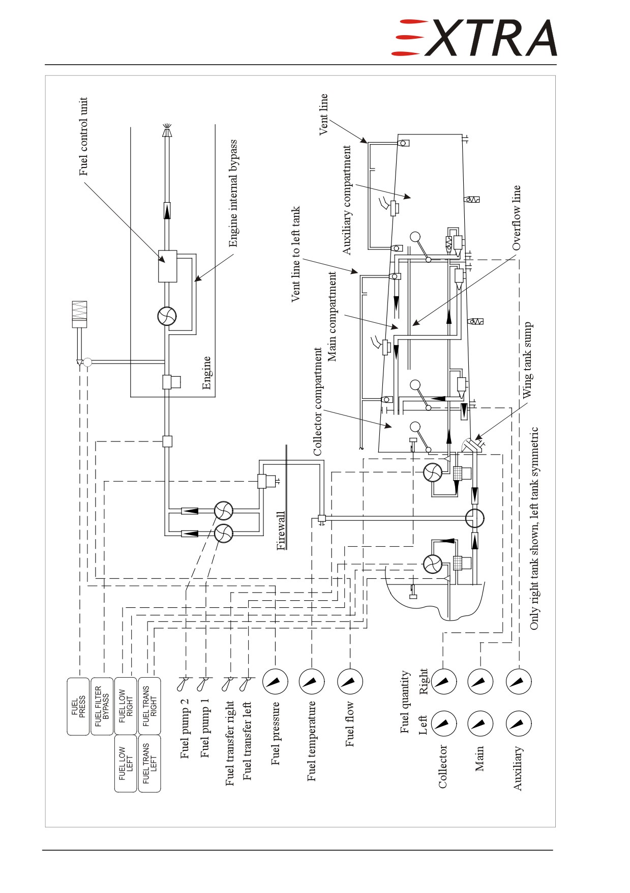
Figure 28-1, Sheet 1
Fuel System Schematic
Page 6 28
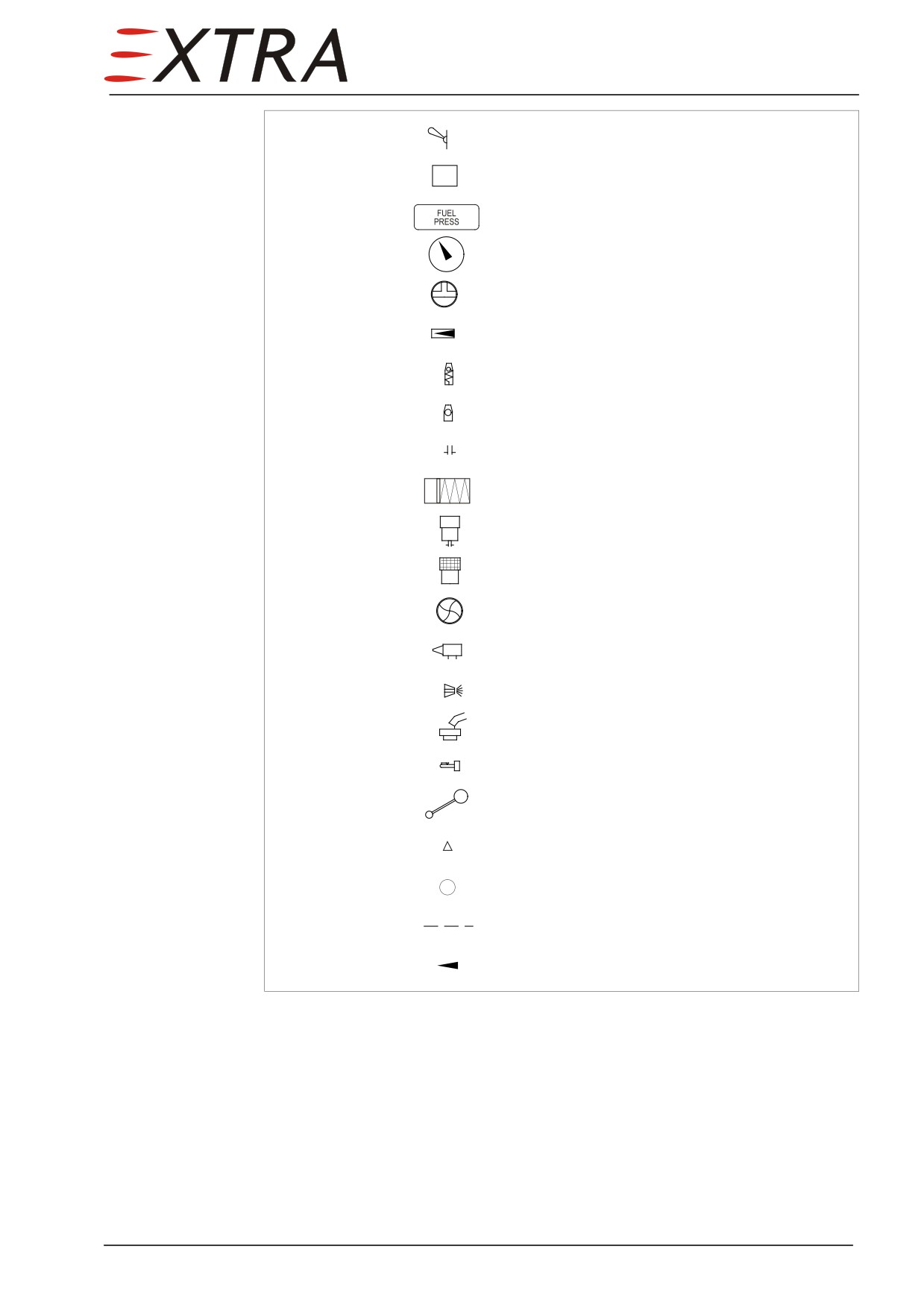
Legend:
Switch
Unit
Annunciator light
Gauge
Selector valve
Check valve
Overpressure relief valve
Float valve
Drain valve
Fuel pressure accumulator
Filter (with drain valve)
Fuel transfer filter
Pump
Jet pump with filter at inlet
Nozzle
Filler neck
Low fuel level switch
Fuel level sensor
Pressure switch
Pressure transducer
Electric wiring
Flow direction
Figure 28-1, Sheet 2
Fuel System Schematic
28 Page 7
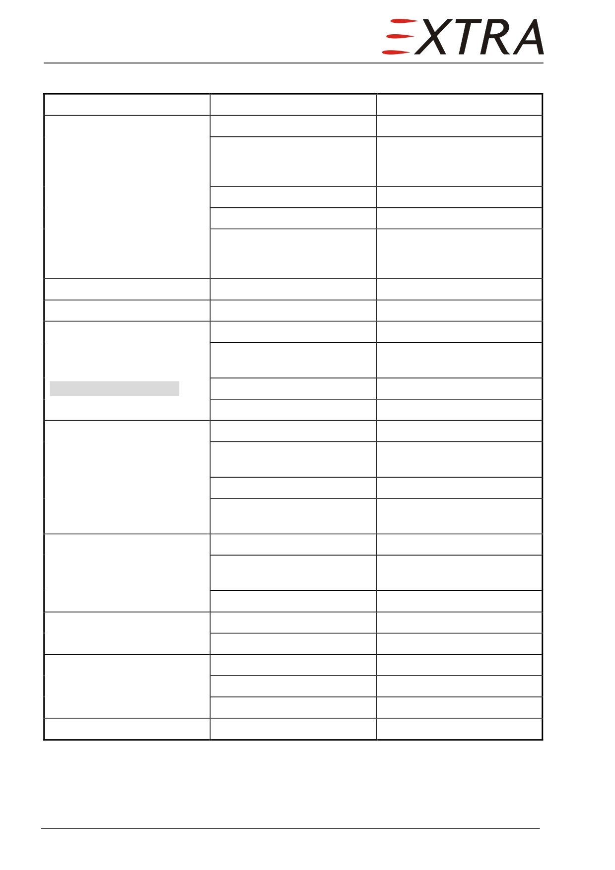
Troubleshooting
Complaint
Possible Cause
Remedy
Fuel tank leakage
Tank sealant damage
Identify and seal
Sump drain leakage
Inspect drain line plumbing
and seal if necessary, or
replace drain
Outer wing flush drain leakage
Replace drain valve.
Relief valve leakage
Replace relief valve/O-ring
Ventline leakage
Inspect float valves, replace if
necessary, seal vent line
connections
Fuel filler leakage
Filler cap O-ring damaged
Replace filler cap O-ring
Fuel line leakage
Line fittings loose
Tighten fittings
Collector compartment not
Fuel transfer filter blocked
Clean filter
full,
Electrical transfer fuel pump
Replace pump
auxiliary tank does not empty
defective
fast enough,
FUEL TRANS LEFT/RIGHT ON
Transfer fuel pick-up blocked
Remove blockage
in flight
Leaking transfer fuel line
Replace fitting or line
Loss of fuel supply
Strainer blocked (tank)
Clean strainer
Check valve (one of four)
Replace check valve
blocked
Selector valve blocked
Replace selector valve
Fuel line blocked
Identify and clean or replace
fuel line
Insufficient fuel supply
Filter blocked
Replace filter element.
pressure reading
Fuel pressure indication
Replace sensor/indicator
defective
Electrical fuel pump failure
Replace fuel pump
Incorrect fuel quantity reading
Float sensor defective
Repair or replace float sensor
Gauge defective
Replace gauge
Incorrect fuel flow indication
Fuel flow sensor defective
Replace sensor
Fuel flow indicator defective
Replace indicator
Wrong K-factor set
Adjust K-factor at indicator
Low fuel warning defective
Fuel low level sensor failure
Replace fuel low level sensor
Page 8 28
Reduction of Fuel Tank Vapor Hazards
General Precautions
During all ventilation or maintenance procedures involving the fuel system,
observe the following general precautions.
•
Defueling should be outdoors with the aircraft at least 100 feet from hangars or
other aircraft.
•
No smoking should be allowed within 100 feet of the aircraft.
•
Suitable fire fighting equipment should be available. Foam or soda type
extinguishing agents are recommended.
•
Ground the aircraft to prevent static electricity from causing sparks. If a ramp
ground is available it should be connected to exhaust stack. If a ramp ground is
not provided, a temporary ground can be obtained by driving a metal rod into
the ground and attaching a ground wire between the rod and the aircraft
exhaust stack.
•
Flame and spark producing equipment should not be operated within 100 feet
of the aircraft.
•
Only personnel working on the aircraft should be allowed in the immediate
area, and no other maintenance should be performed while the tanks are being
worked on.
•
When a fuel tank is opened for repair, air ventilation (refer to Page 7) should be
started immediately to reduce vapor concentrations.
•
When draining fuel, ensure that suitable containers are available and that
drained fuel is stored safely. Do not allow fuel to drip to the ground and form
pools.
•
If it is necessary to ventilate a tank when the aircraft is in hangar, ensure that
vapors do not accumulate to explosive or toxic levels in the hangar.
When fuel is being drained, there is little control over the release of fuel
WARNING
vapor. This vapor should be dissipated as quickly as possible by smoothly
blowing shop air into the tank.
Air Ventilation
•
Completely drain the fuel system per Chapter 12-10-02.
•
Remove inspection doors (refer to Chapter 28-11-03) and tank caps.
•
Use compressed air or an explosion-proof blower to blow air into the tank until
tank interior is dry and free of vapor.
•
Continue ventilation whenever tank is open and being worked on.
If flammable vapors from cleaning solvents are allowed in the tank
WARNING
increase air circulation to dissipate them.
28 Page 9
28-10-00
STORAGE
Description
The aircraft has six integral wing tanks between the wing spars. Each wing side
has a main, auxiliary, and collector compartment. The latter is kept full by a jet
pump driven fuel transfer system in flight.
The collector compartment features a fuel level sensor, a sump with drain, a
strainer and a pick-up tube behind it. The low fuel sensor is also located here.
Three flapper type check valves separate the collector compartment from the
main compartment to make sure fuel cannot flow out, but can flow in, in case
of a fuel transfer system failure. The collector compartment can be inspected
from the main compartment by opening the rib in which these valves are
mounted or from the avionic compartment (center wing) by removing the
inspection door on which the fuel quantity probe is installed.
The main compartment has its own fuel level sensor mounted on the inner
wing inspection door. The vent system has two float valves and an outlet. The
vent systems of the two main tanks are interconnected. Each tank has a 1psi
overpressure relief valve in the aft spar for the case the normal vent system
fails. The main tanks have a Ø 75mm filler cap for JET-A1 with a titanium ring
around it for static bonding.
The auxiliary compartment also has a filler cap, vent system
(including
overpressure relief valve) and fuel level sensor, but is not directly connected to
the fuel distribution system. As long as the auxiliary compartment is filled fuel
is pumped from there into the main compartment by means of the fuel transfer
system.
Observe the safety notes given in Chapter 12-10-01.
DANGER
For all maintenance work on the tanks, drain them completely and
WARNING
appropriate open tank hatches on top of the wing. Be aware of fuel fumes
and fuel stained cloth: highly inflammable!
Power must be off, no external power connected, room well ventilated.
NOTE
If the tank has been opened, a tank leakage test is mandatory. Refer to
Subject 28-10-01 Leakage Test.
Page 10 28