Extra 500. Maintenance Manual (2012) - page 6

22-10-01
Roll Servo
Removal
Refer to Figure 22-2.
Detail Steps/Work Items
Key Items
1
Ensure BATT switch is OFF and no external
power connected.
2
Remove wing center fairing.
Refer to Chapter 51-00-01
3
Disconnect electrical connector from roll
servo.
4
Loosen bridle cable clamps.
5
Remove 3 bolts and nuts securing roll servo
to support bracket.
6
Remove roll servo from support bracket.
7
Remove cable guard, cover and bridle cable
from servo capstan, if required.
22 Page 13
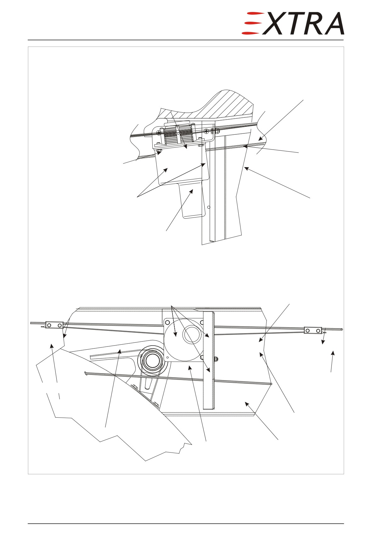
Top View
Upper control cable
fwd
bridle cable center ball
bridle cable
bridle cable
Attachment bolts
Lower control cable
Roll Servo
Front View
Attachment bolts
Upper control cable
Cable clamp
Cable clamp
bridle cable end
bridle cable end
bridle cable
bridle cable
Roll Servo
Lower control cable
Figure 22-2
Roll Servo Installation
Page 14 22
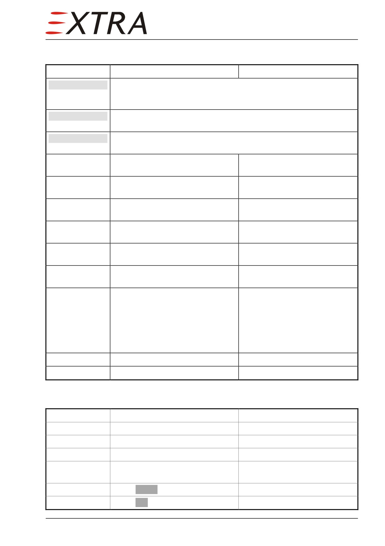
Installation
Detail Steps/Work Items
Key Items
IMPORTANT
Prior to installing roll servo, adjust clutch torque and determine proper
direction of capstan rotation. See Section 22-10-04 for clutch torque
settings.
IMPORTANT
Prior to installing roll servo, check aileron control system travels. Check
aileron cable tension in accordance with Chapter 27-00-01.
IMPORTANT
Removal of servo requires disconnecting the bridle cable. Consequently,
bridle cable tensioning is required upon reinstallation of the servo.
1
Ensure BATT switch is OFF and no
external power connected.
2
Attach roll servo with 3 screws to
support bracket.
3
Insert bridle cable center ball into
leading hole in capstan.
4
Adjust position of center ball with
12 o’clock position.
aileron controls in neutral position.
See Figure 22-2
5
Wrap bridle cable around capstan 1.5
Cable clamps will be positively
turns each direction from center ball.
guided to correct position
6
Install cable guards and cover with 4
Tighten screws only snugly against
screws and washers.
servo base plate
Apply tension by hand before
7
Install cable clamps.
tightening the cable clamps.
Adjust bridle cable tension to the
See 22-10-07Figure 22-6 for clamp
value given in Subject 22-10-06.
torquing.
Cable clamps may be rotated on
aileron cable to align bridle cable
with capstan grooves.
8
Connect electrical connector.
9
Install wing center fairing.
Refer to Chapter 51-00-01
Function Test
Detail Steps/Work Items
Key Items
1
Attach external power to the aircraft.
2
Check all switches off.
3
Switch EXT PWR on.
4
Switch AUTOPILOT MASTER to
MASTER.
5
Check AP RDY on IFD.
6
Check RDY on autopilot computer.
22 Page 15
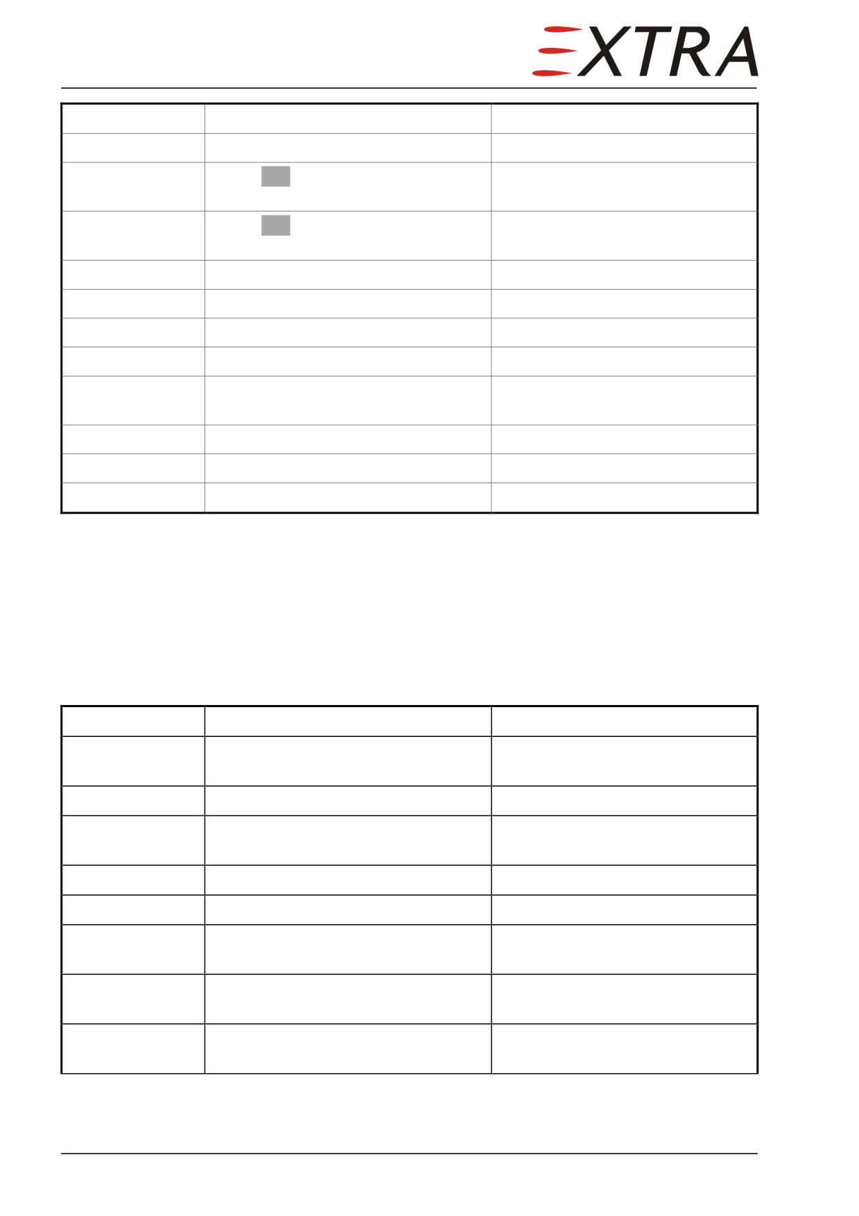
Detail Steps/Work Items
Key Items
7
Switch on HDG mode.
8
Check HDG is displayed on autopilot
computer.
9
Check HDG bug is fully filled and
magenta on IFD.
10
Turn HDG knob to the left.
10
Check control wheel turns CCW.
11
Turn HDG knob to the right.
12
Check control wheel turns CW.
13
Press AP DISC switch on LH control
Aural warning can be heard.
wheel.
14
Switch AUTOPILOT MASTER off.
15
Switch EXT PWR off.
16
Disconnect external power.
22-10-02
Pitch Servo
Removal
Refer to Figure 22-3.
Detail Steps/Work Items
Key Items
1
Ensure BATT switch is OFF and no
external power connected.
2
Remove tail cone access panel.
3
Disconnect electrical connector from
roll servo.
4
Loosen bridle cable clamps.
5
Remove return pulley.
6
Remove 4 bolts and nuts securing
pitch servo to support bracket.
7
Remove pitch servo from support
bracket.
8
Remove cable guard, cover and bridle
cable from servo capstan, if required.
Page 16 22
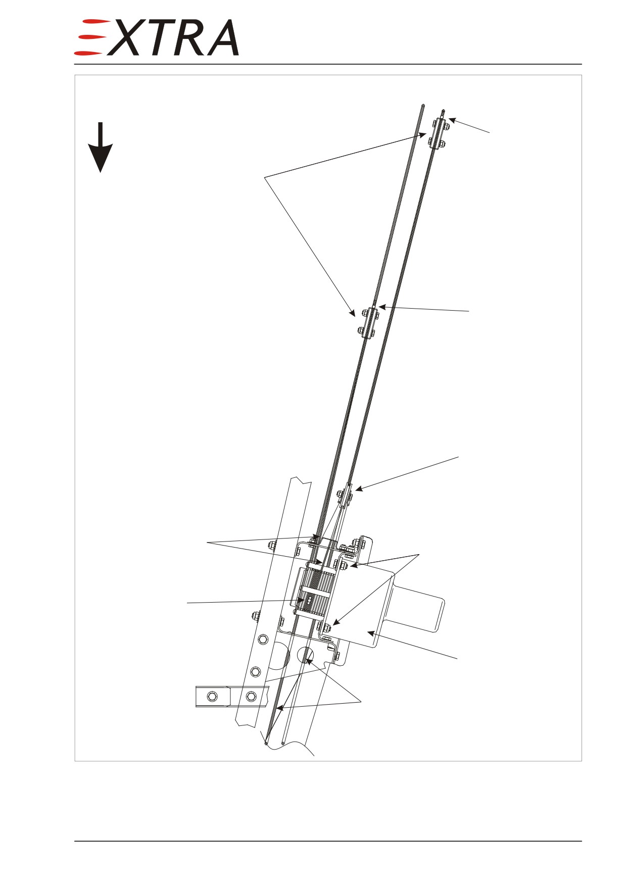
Top View
fwd
bridle cable
longer end
Cable clamps
bridle cable
shorter end
Pulley
bridle cable
Attachment bolts
bridle cable
center ball
Pitch servo
Control cable
Figure 22-3
Pitch Servo Installation
22 Page 17
Installation
Detail Steps/Work Items
Key Items
IMPORTANT
Prior to installing pitch servo, adjust clutch torque and determine
proper direction of capstan rotation. See Section 22-10-04 for clutch
torque settings.
IMPORTANT
Prior to installing pitch servo, check elevator control system travels.
Check elevator cable tension in accordance with Ch. 27-00-01.
IMPORTANT
Removal of servo requires disconnecting the bridle cable. Consequently,
bridle cable tensioning is required upon reinstallation of the servo.
1
Ensure BATT switch is OFF and no
external power connected.
2
Attach pitch servo with 4 screws to
support bracket.
3
Insert bridle cable center ball into
leading hole in capstan.
4
Adjust position of center ball with
11 o’clock position.
elevator controls in neutral position.
See Figure 22-3
5
Wrap bridle cable around capstan
Cable clamps will be positively
1 turn (360°) CW and 1.5 turns (540°)
guided to correct position
CCW from center ball.
6
Install cable guards and cover with 4
Tighten screws only snugly against
screws and washers.
servo base plate
7
Install return pulley.
See 22-10-07Figure 22-6 for clamp
8
Lead upper bridle cable segment
torquing.
around pulley and pre-install cable
Cable clamps may be rotated on
clamps.
elevator cable to align bridle cable
Tension bridle cable by hand before
with capstan grooves
fastening the cable clamps.
9
Connect electrical connector.
10
Adjust correct bridle cable tension.
Refer to the Tension Settings and
the Tensioning procedure presented
in Subject 22-10-06.
11
Install tail cone access panel.
Page 18 22
Function Test
Detail Steps/Work Items
Key Items
1
Attach external power to the aircraft.
2
Check all switches off.
3
Switch EXT PWR on.
4
Switch AUTOPILOT MASTER to
MASTER.
5
Check AP RDY on IFD.
6
Check RDY on autopilot computer.
7
Set heading bug to current heading
push heading knob on keypad
8
Switch on HDG mode.
9
Switch on VS mode.
10
Check ALT bug is open.
11
Check VS bug is filled and magenta on
IFD.
12
Check control wheel moves forward.
13
Set VS bug to +1000 ft.
14
Control wheel moves aft or at least
On the ground the servo does not
tries.
have enough power.
15
Press AP DISC switch on LH control
Aural warning can be heard.
wheel.
16
Switch AUTOPILOT MASTER off.
17
Switch EXT PWR off.
18
Disconnect external power.
22-10-03
Yaw Servo
Removal
Refer to Figure 22-4.
Detail Steps/Work Items
Key Items
1
Ensure BATT switch is OFF and no
external power connected.
2
Remove tail cone access panel.
3
Disconnect electrical connector from
roll servo.
22 Page 19

Detail Steps/Work Items
Key Items
4
Loosen bridle cable clamps.
5
Remove 4 bolts and nuts securing yaw
servo to support bracket.
6
Remove yaw servo from support
bracket.
7
Remove cable guard, cover and bridle
cable from servo capstan, if required.
Page 20 22
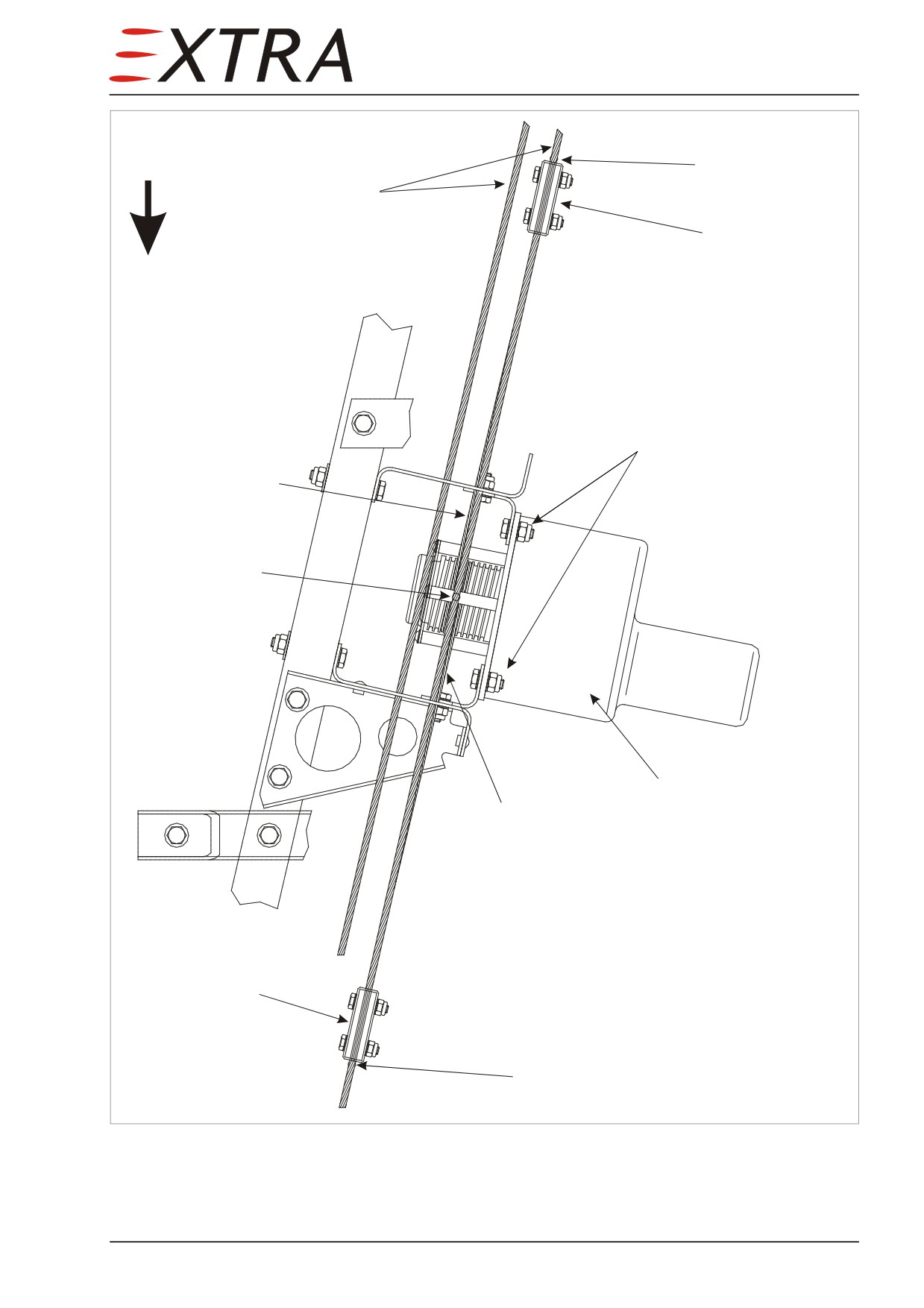
Top View
Bridle cable end
Control cable
fwd
Cable clamp
Attachment bolts
Bridle cable
Bridle cable
center ball
Yaw servo
Bridle cable
Cable clamp
Bridle cable end
Figure 22-4
Yaw Servo Installation
22 Page 21
Installation
Detail Steps/Work Items
Key Items
IMPORTANT
Prior to installing yaw servo, adjust clutch torque and determine proper
direction of capstan rotation. See Section 22-10-04 for clutch torque
settings.
IMPORTANT
Prior to installing yaw servo, check elevator control system travels.
Check elevator cable tension in accordance with Ch. 27-00-01.
IMPORTANT
Removal of servo requires disconnecting the bridle cable. Consequently,
bridle cable tensioning is required upon reinstallation of the servo.
1
Ensure BATT switch is OFF and no
external power connected.
2
Attach yaw servo with 4 screws to
support bracket.
3
Insert bridle cable center ball into
leading hole in capstan.
4
Adjust position of center ball with
12 o’clock position
rudder controls in neutral position.
See Figure 22-4
5
Wrap bridle cable around capstan 1.5
Cable clamps will be positively
turns each direction from center ball.
guided to correct position
6
Install cable guards and cover with 4
Tighten screws only snugly against
screws and washers.
servo base plate
7
Lead upper bridle cable segment
See Figure 22-6 for clamp torquing.
around pulley and install cable clamps
Cable clamps may be rotated on
Adjust bridle cable tension to the
elevator cable to align bridle cable
value given in Subject 22-10-06.
with capstan grooves
8
Connect electrical connector.
9
Install tail cone access panel.
Function Test
Detail Steps/Work Items
Key Items
1
Attach external power to the aircraft.
2
Check all switches off.
3
Switch EXT PWR on.
4
Switch AUTOPILOT MASTER to
MASTER.
5
Engage heading mode
6
Switch AUTOPILOT YAW DAMPER on.
7
Turn YAW TRIM potentiometer to the
left.
Page 22 22
Detail Steps/Work Items
Key Items
8
Check rudder pulses to the left.
9
Turn YAW TRIM potentiometer to the
right.
10
Check rudder pulses to the right.
11
Press AP DISC switch on LH control
wheel.
12
Switch AUTOPILOT YAW DAMPER off.
13
Switch EXT PWR off.
14
Disconnect external power.
22-10-04
Clutches (Pitch, Roll and Yaw Servo)
Torque Settings
The following torque settings must be checked and adjusted:
Servo P/N
Clutch Torque
Servo RPM @24VDC
setting
(fixed, not adjustable)
Pitch S-TEC 0108-P4
29 ± 2 inlbs
1.08
Roll S-TEC 0106-R2
36 ± 2 inlbs
2.40
Yaw S-TEC 0106-6-Y9
73 ± 2 inlbs
3.59
22 Page 23
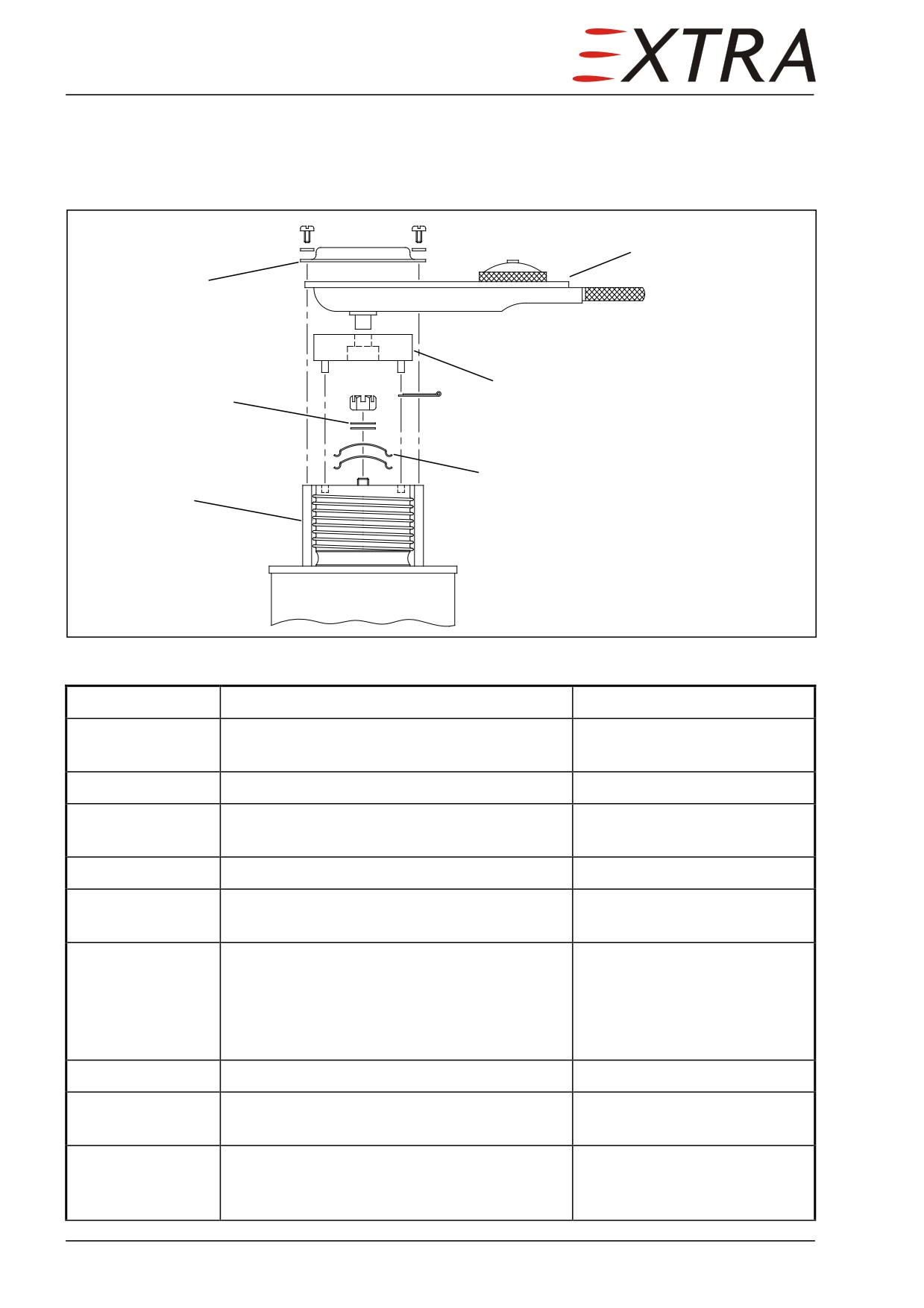
Torque Adjustment
Before re-installation of a servo, perform the following steps to check and
adjust clutch torque value in accordance with the Torque Settings given above.
Dial Torque Wrench
Capstan Cover
Shim Washer
Tool S-TEC P/N 6622-1
Cable Guard
Tension Washer
Figure 22-5
Clutch Torque Adjustment
Detail Steps/Work Items
Key Items
1
Remove capstan cover from servo with 4
screws and washers.
2
Draw cotter pin from castle nut.
3
Insert adapter tool (S-TEC P/N 6622-1) into
leading holes in servo capstan.
4
Bear dial torque wrench.
5
Connect servo motor to 28 VDC power
Servo shaft rotates
source.
6
Read torque value.
See Torque Settings chart of
Subject 22-10-04 for
appropriate settings. Perform
clutch torque adjustment as
per step 7 - 8, if necessary
7
Remove torque wrench and adapter tool.
8
Align torque value with castle nut - turn CW
to increase and CCW to decrease torque.
9
Repeat steps 3 to 8, until read torque setting
(step 6) matches value given in Torque
Settings chart of Subject 22-10-04.
Page 24 22
Detail Steps/Work Items
Key Items
10
Disconnect servo motor.
11
Re-install cotter pin.
NOTE
To align cotter pin with shaft hole, use shim washers S - TEC
P/N 1205 S 5 - 005, 007, 010, 031 in any combination (min. 1 required).
12
Re-install capstan cover.
NOTE
After capstan cover has been installed, determine that there is no
interference between capstan and cover.
22-10-05
Driving Wheels
Removal/Installation
Detail Steps/Work Items
Key Items
1
Draw cotter pin from castle nut.
2
Remove castle nut.
3
Remove 2 tension washers.
4
Remove driving wheel.
IMPORTANT
After removal of driving wheel, clutch
Refer to Section 22-10-04 for
torque adjustment is required.
torque settings.
5
Install in reverse order of removal.
22-10-06
Bridle Cables
Removal/Installation
Detail Steps/Work Items
Key Items
1
Unfasten cable clamp bolts as far as
On both ends
necessary to unthread the bridle cable.
2
Uncoil the bridle cable from the servo.
3
Install in reverse order of removal.
Observe correct position of
bridle cable center ball. Refer
to applicable servo
Installation Procedure.
22 Page 25
Tension Settings
The following tension settings must be checked
(cable tensiometer) and
adjusted:
Bridle Cable
Tension Setting
Pitch
32 ± 2 lbs
Roll
15 ± 2 lbs
Yaw
15 ± 2 lbs
Tensioning
Generally the necessary tension can be applied by hand to the bridle cables
before tightening the cable clamp bolts.
However for tensioning the pitch servo bridle cable the power of the pitch
servo itself is necessary to receive the correct tension values. Proceed as
follows (refer to Figure 22-3):
Detail Steps/Work Items
Key Items
1
Install the bridle cables as per Subject 22-
10-02.
2
Fix control wheel in neutral position by
hand.
3
Switch on AUTOPILOT MASTER.
4
Switch on the VS Mode on the Autopilot
Programmer/Computer.
5
Position VS bug to +1000 ft.
Control wheel tries to move
aft. Counteract by hand. The
pitch servo now tensions the
longer bridle cable end.
6
Loosen cable clamp of the shorter bridle
The tension applied here by
cable end, tension by hand, and retighten
hand allows adjusting the
cable clamp bolts.
bridle cable to the desired
tension.
7
Switch off AUTOPILOT MASTER.
8
Check bridle cable tension.
Use a conventional cable
tensiometer.
9
Repeat procedure if necessary varying
tension on step 6.
Page 26 22
22-10-07
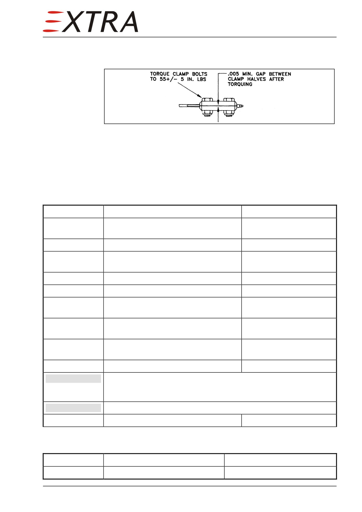
Cable Clamps
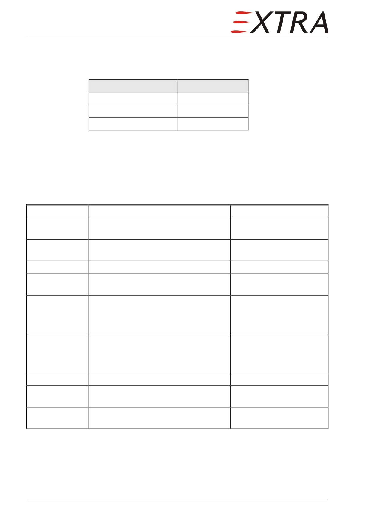
Observe the following values when installing/fastening the cable clamps.
Figure 22-6
Cable Clamp Torquing
22-10-08
Trim Servo
Removal/ Installation
Detail Steps/Work Items
Key Items
1
Ensure BATT switch is OFF and no external
power connected.
2
Remove tail cone access panel.
3
Disconnect electrical connector from trim
servo.
4
Remove swivel from transmission chain.
5
Remove transmission chain.
6
Remove 4 bolts and nuts securing servo
support bracket to GFK base.
7
Remove 4 bolts and nuts securing trim servo
to support bracket.
8
Move trim servo with driving wheel to the
right fuselage side out of support bracket.
9
Remove trim servo in forward direction.
IMPORTANT
Prior to installing trim servo, check and
adjust
clutch torque
and
determine proper direction of driving wheel rotation. See Section 22-10-
04 for clutch torque settings.
IMPORTANT
Prior to installing trim servo, check trim tab control system.
10
Install in reverse order of removal.
Function Test
Detail Steps/Work Items
Key Items
1
Attach external power to the aircraft.
22 Page 27
Detail Steps/Work Items
Key Items
2
Check all switches off.
3
Switch EXT PWR on.
4
Switch AUTOPILOT PITCH TRIM on.
5
Move (complete) TRIM switch on the
LH control wheel forward.
6
Check trim wheel (upper part) turns
forward.
7
Move (complete) TRIM switch on the
LH control wheel aft.
8
Check trim wheel (upper part) turns
aft.
9
Press AP DISC switch on LH control
wheel.
10
Switch AUTOPILOT PITCH TRIM off.
11
Switch EXT PWR off.
12
Disconnect external power.
22-10-09
Trim Servo Clutch
Torque Settings
The following torque setting must be checked and adjusted:
Servo P/N
Clutch Torque
Servo RPM @24VDC
setting
(fixed, not adjustable)
Trim S-TEC 0106-2-T3
36 ± 2 inlbs
11.03
Torque Adjustment
Before re-installation, perform the following steps to check and adjust clutch
torque value given above.
Detail Steps/Work Items
Key Items
Measuring
1
Draw cotter pin from castle nut.
2
Insert adapter tool (S-TEC P/N 6622-1) into
leading holes in driving wheel.
3
Bear dial torque wrench.
Page 28 22
Detail Steps/Work Items
Key Items
4
Connect servo motor to 28 VDC power
Servo shaft rotates
source.
5
Read torque value.
See above for appropriate
torque settings. Perform
clutch torque adjustment as
per step 6 - 7,
if necessary
Adjustment
6
Remove torque wrench and adapter tool.
7
Align torque value with castle nut - turn CW
to increase and CCW to decrease torque.
8
Repeat steps 2 to 7, until read torque setting
(step 5) matches value given above.
9
Disconnect servo motor.
10
Re-install cotter pin.
NOTE
To align cotter pin with shaft hole, use shim washers S - TEC
P/N 1205 S 5 - 005, 007, 010, 031 in any combination (min. 1 required).
22-10-10
Pressure Transducer
Removal/Installation
Detail Steps/Work Items
Key Items
1
Ensure BATT switch is OFF and no
external power connected.
2
Remove tail cone access panel.
Refer to Chapter 51-00-01.
3
Disconnect electrical connector from
pressure transducer.
4
Disconnect pressure hose from
Cut cable tie
pressure transducer.
5
Remove pressure transducer.
2 bolts
6
Install in reverse sequence of removal.
Fasten pressure hose with new
cable tie.
22 Page 29
22-10-11
Yaw Amplifier
Removal/Installation
Detail Steps/Work Items
Key Items
1
Ensure BATT switch is OFF and no
external power connected.
2
Remove tail cone access panel.
3
Disconnect electrical connector from
yaw amplifier.
4
Remove pressure yaw amplifier.
4 bolts
5
Install in reverse sequence of removal.
22-10-12
Programmer/Computer
Removal/Installation
Detail Steps/Work Items
Key Items
1
Ensure BATT switch is OFF and no
external power connected.
2
Place a Allen key in hole between REV
Computer will come out.
and ALT key, rotate CCW.
3
Pull out rest of the way.
Do not pull on VS knob!
4
Remove programmer/computer
5
Install in reverse sequence of removal.
Use Allen key, rotate CW until
computer sits firmly in rack, flush
with panel.
6
Perform heading calibration procedure
Refer to Subject 22-10-00 Heading
Calibration
22-10-13
Turn Coordinator
Removal/Installation
Detail Steps/Work Items
Key Items
1
Ensure BATT switch is OFF and no
external power connected.
Page 30 22

Detail Steps/Work Items
Key Items
2
Remove RH IFD.
Refer to Chapter 31-60-01.
3
Disconnect electrical wiring.
4
Remove turn coordinator.
4 screws
5
Install in reverse sequence of removal.
6
Perform heading calibration procedure
Refer to Subject 22-10-00 Heading
Calibration
22 Page 31
Chapter 23
Communications
23 Page 1
Table of Contents
23-00-00
GENERAL
3
Description.......................................................................................................... 3
Troubleshooting
.................................................................................................. 3
23-10-00
SPEECH COMMUNICATION
...................................................................... 5
Description.......................................................................................................... 5
Operation
............................................................................................................ 5
23-50-00
AUDIO INTEGRATING
................................................................................. 6
23-50-01
Intercom System PS Engineering PMA8000B(-T)
........................................ 6
Description.......................................................................................................... 6
Operation
............................................................................................................ 6
Removal
.............................................................................................................. 6
Installation
.......................................................................................................... 6
Tests and Checks
................................................................................................ 7
23-50-02
COM Antennas
................................................................................................. 8
Description.......................................................................................................... 8
Removal/Installation
........................................................................................... 8
23-50-03
NAV Antenna
.................................................................................................... 9
Description.......................................................................................................... 9
Removal/Installation
........................................................................................... 9
23-60-00
STATIC DISCHARGING
............................................................................. 10
General.............................................................................................................. 10
Description........................................................................................................ 10
Figure 23-01
Lightning Protection/Static Discharging System
11
Page 2 23
Page Date:
11. July 2012

23-00-00
GENERAL
Description
The EXTRA 500 is equipped with a speech and entertainment communication
system, consisting of the following devices:
1 Avidyne Entegra Release 9 IFD System
2 PS Engineering PMA8000B(-T) Stereo Intercom System
3 COM 1, 2, and Marker Antennas
The system units (1 and 2) are mounted to the instrument panel, the antennas as
shown on Figure 23-01.
In Chapter 23-10-00 Speech Communication you will find information about
Avidyne Entegra Release 9 IFD System.
The related PS Engineering PM8000B(-T) devices and the COM antennas are
subject to Chapter 23-50-00 Audio Integrating.
Chapter 23-60-00 Static Discharging contains a description of the EXTRA 500
bonding system.
Troubleshooting
Complaint
Possible Cause
Remedy
Unable to transmit or receive
No power on load bus
Switch on starter/generator or
external power.
Defective AUDIO-MRK breaker
Replace
Unable to transmit or receive
Defective LH IFD
Replace LH IFD
COM I
Unable to transmit or receive
Defective RH IFD
Replace RH IFD
COM II
Unable to transmit with IFD
No or defective antenna cable
Check antenna cable
indication
connections
connections
COM [1/2] TX Fault
Unable to transmit from the
Defective transmit button on
Replace
pilot's side (missing transmit
pilot's side
mode indicator on display)
Defective wiring between
Repair
pilot's transmit button and
radio unit
Unable to transmit from the
Defective transmit button on
Replace
co-pilot's side (missing
co-pilot's side
transmit mode indicator on
Defective wiring between co-
Repair
display)
pilot's transmit button and
radio unit
No modulation when
Defective pilot's headset
Replace
transmitting from pilot's seat
Defective wiring
Repair
23 Page 3
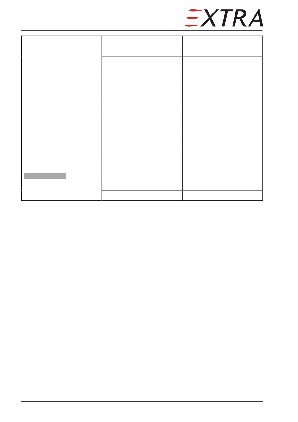
Complaint
Possible Cause
Remedy
No modulation when
Defective co-pilot's headset
Replace
transmitting from co-pilot's
Defective wiring
Repair
seat
Short range in transmit mode;
Defective radio unit
Repair
reception without problems
Short range in receive mode;
Defective radio unit
Repair
signal noise in reception
Short range in transmit and
Defective COMM antenna,
Repair or replace
receive mode; signal noise in
coaxial cable and plug
reception
Speaker silent, headsets
Defective speaker
Replace
operation normal
Defective wiring
Repair
Defective intercom unit
Replace
Transmit mode indicator on
Transmit button stuck
Replace
display is always visible
COM [1/2] Stuck TX
Intercom system inoperative,
Defective intercom unit
Replace
transmit mode O.K.
Defective wiring
Repair
Page 4 23
23-10-00
SPEECH COMMUNICATION
Description
The EXTRA 500 airplane is equipped with an Avidyne
700-00083-000
Integrated Flight Display (IFD) in the left (PFD) position and either another
700-00083-000 IFD in the right (MFD) position. A Control Display Unit
(CDU) p/n 700-00150-002 is also installed as part of the Entegra Release 9
IFD System and located on the middle console. Refer to Chapter 31-60 for
more information.
The system is integrated to:
• S-TEC System 55X Autopilot
• Audio panel
• Remote transponder
• DME (optional)
• Weather detection (optional)
• Traffic advisory (optional)
Operation
Refer to POH EXTRA 500.
23 Page 5
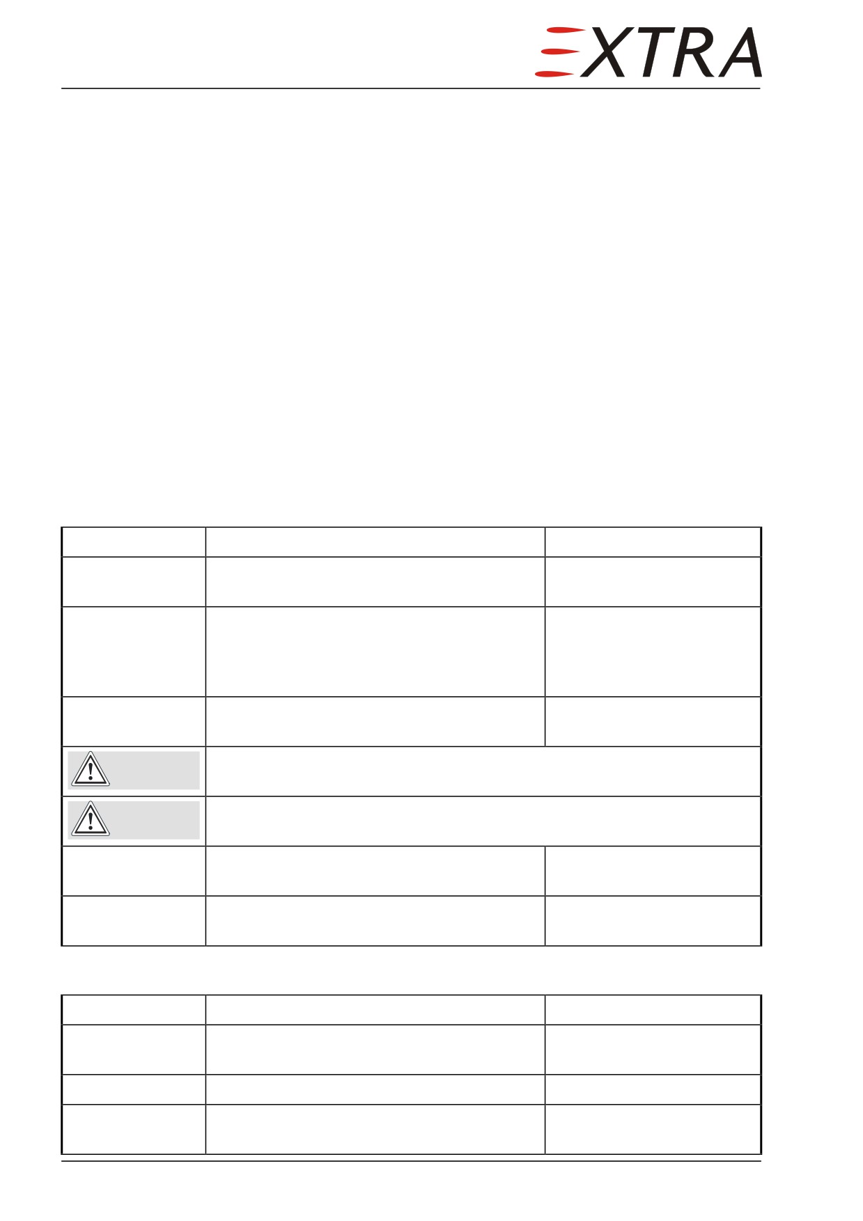
23-50-00
AUDIO INTEGRATING
23-50-01
Intercom System PS Engineering PMA8000B(-T)
Description
The PMA8000B and PMA8000BT are audio isolation amplifier and audio
selector that contain an automatic voice activated (VOX) intercom system and
integral marker beacon receiver. They can switch two transceivers (Com 1,
Com 2) and six receivers (Com 1, Com 2, Nav 1, Nav 2, DME, and MKR).
Operation
Refer to EXTRA 500 Pilot's Operating Handbook.
Removal
Detail Steps/Work Items
Key Items
1
Ensure BATT switch is OFF and no external
power connected.
2
Put a 3/32 Allen wrench into the center access
hole between the Com2 and Mon1 push
buttons for the locking screw in the front
panel. Engage the screw.
3
Turn the screw counter-clockwise until the
unit disengages from the mounting rack.
Do not pull on the knobs. Do not pry the face plate. You can damage the
CAUTION
unit.
Do not touch the connector card at the rear of the unit. The electrostatic
CAUTION
charge on your body can damage the unit.
4
Pull the sides of the unit gently to remove it
from the mounting rack.
5
Install the protective covers on the rear
connectors of the unit.
Installation
Detail Steps/Work Items
Key Items
1
Remove the protective covers from the rear
connectors of the unit.
2
Slide the unit into the rack.
3
Engage the locking screw so that the latch
front lobe touches the rack.
Page 6 23

Detail Steps/Work Items
Key Items
4
Turn the locking screw clockwise so that the
rear lobe engages the mounting rack.
Do not over-tighten the locking screw. You can damage the locking
CAUTION
mechanism.
5
Continue to turn the screw until the unit is
fully installed in the mounting rack.
6
Perform a function test.
See Tests and Checks
below.
Tests and Checks
Perform the applicable operational checkout presented in the Avidyne System
Installation and Operation Manual (LOAP 37) or (LOAP 38) whenever the unit
has been reinstalled.
23 Page 7
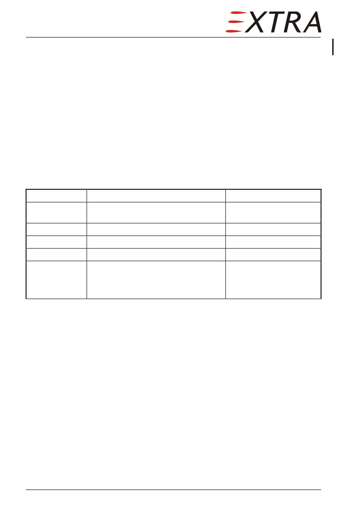
23-50-02
COM Antennas
Description
For communication transmitting and receiving conventional antennas
(COM 1, 2, and Marker) are used (refer to Figure 23-01).
The antennas are attached to the fuselage by a ground plate. The lightning
protection sheet is placed between the ground plate and the fuselage structure
and thus ensures bonding. Connection is made via conventional BNC plugs and
sockets.
The Marker and COM 2 antenna is integrated in the structure of the ventral fin.
Maintenance should not be required. In case access to these antennas is
required, contact EXTRA.
Removal/Installation
Detail Steps/Work Items
Key Items
1
Ensure BATT switch is OFF and no external
power connected.
2
Disconnect BNC plug.
3
Remove attachment nuts.
4
Remove antenna.
5
Install in reverse sequence of removal.
Ensure lightning protection
sheet is placed between
fuselage structure and ground
plate.
Page 8 23
Page Date:
11. July 2012
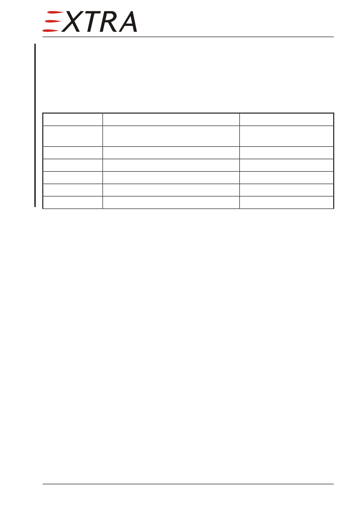
23-50-03
NAV Antenna
Description
From serial N° 1003 the NAV antenna is installed on the fin tip.
Removal/Installation
Detail Steps/Work Items
Key Items
1
Ensure BATT switch is OFF and no external
power connected.
2
Remove NAV antenna access panel.
Refer to Chapter 51-00-01
3
Remove attachment bolts.
4
Remove antenna.
5
Disconnect BNC plug.
6
Install in reverse sequence of removal.
Page Date:
11. July 2012
23 Page 9
23-60-00
STATIC DISCHARGING
General
A special bonding system is necessary for the composite structure of the
EXTRA 500. The composite structure does not sufficiently conduct electricity.
Lightning protection aluminium sheets are attached to the inner fuselage skin
to make a conduct path. Attachment is made by fabric layers and
interconnections between sheets are made by rivets.
All metal components are bonded to the aluminium sheets by copper leads.
Some components are directly connected to the aluminium sheets when
attached (so as the COM 1, 2, and Marker antenna).
Description
A main aluminium sheet is routed from the firewall to the right side of the
inner fuselage and then to the rear. Several extensions are routed to the wing,
landing gear, antennas and other equipment as shown on Figure
23-01
(Figure 23-01 only shows the lightning protection system and equipment as far
as applicable for communication system static discharging).
Page 10 23
Page Date:
11. July 2012
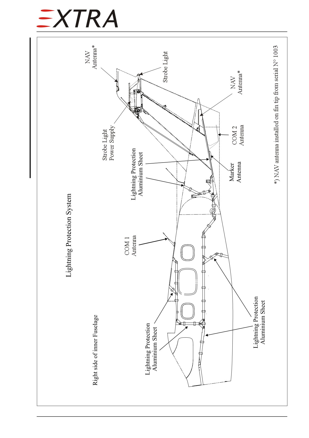
Figure 23-01
Lightning Protection/Static Discharging System
Page Date:11. July 2012
23 Page 11
Chapter 24
Electrical Power
24 Page 1
Table of Contents
24-00-00
GENERAL
3
Description.......................................................................................................... 3
Figure 24-1
Electrical System Schematic
............................................................................... 4
Figure 24-2
Left Side Panel Switches
..................................................................................... 5
Figure 24-3
Left Side Panel Circuit breakers
6
Troubleshooting
.................................................................................................. 7
24-30-00
DC GENERATION
.......................................................................................... 9
24-30-10
Starter-Generator
............................................................................................. 9
Removal/Installation
........................................................................................... 9
24-30-11
Generator Control Unit (GCU)
....................................................................... 9
Removal/Installation
10
24-30-20
Standby Alternator
10
Removal/Installation
10
24-30-21
Alternator Regulator
10
Removal/Installation
11
24-30-30
Battery
11
Charging with external power
11
Charging over charger plug
12
Removal/Installation
12
24-30-40
Indication
12
24-30-41
Indicator Cluster
12
Removal/Installation
13
24-40-00
EXTERNAL POWER
14
Description
14
24-60-00
DISTRIBUTION
15
Description
15
24-60-01
E-box
16
Removal/Installation
16
24-60-02
Switches
16
Removal/Installation
16
24-60-03
Circuit Breakers
17
Removal/Installation
17
24-60-04
Relays
17
24-60-05
Shunts
17
24-60-06
Fuses
17
Page 2 24