Extra 500. Maintenance Manual (2012) - page 4
12-10-02
Draining
During the aircraft defueling observe the safety precautions specified in
DANGER
Section 12-10-01.
Do not drain the fuel system when the engine or the exhaust is hot or while
DANGER
the wind is strong.
Even after completely draining the fuel system fuel may rest inside the
WARNING
engine and in the fuel lines downstream the check valves; which are
located next to the fuel pumps. This fuel may be pressurized.
The fuel system can be completely or partly drained.
When fuel system shall be completely drained ensure fuel selector valve is set
to BOTH. Drain at all fuel drains (for locations refer to Subject 12-10-03).
When fuel system shall be partly drained ensure fuel selector valve is set to
OFF. Then the individual fuel compartments and the area downstream the fuel
selector valve can be drained over their respective drain valves. Consider that
the collector and main compartments are connected by a check valve. So
draining the collector compartment will also reduce fuel quantity in the main
compartment.
A quantity of fuel must be drained prior to the first flight of the day and at least
five min. after refueling to inspect for water and/or contamination. Continue
draining until free of water or contamination.
IMPORTANT
After draining, make sure the fuel drain valve is returned to the closed
position and the valve is not leaking.
12-10-03
Fuel Drains
The EXTRA 500 is equipped with 12 fuel drains on the locations as given in
the following table:
Designation
Location
Inner and outer auxiliary compartment
Each outboard wing
drains
Inner and outer main compartment drains
Each center wing
Collector compartment drains
Fuel sump next to each root rib
Lowest point drain
Down stream of the fuel selector
valve, accessible by an opening in
the forward keel beam access
panel.
Fuel filter drain
Next to the fuel filter, accessible
by an opening in the fuel filter
access panel.
Page 6 12
Page Date:
12-10-04
Replenishment of Engine Oil
The engine oil replenishment is accomplishment by pouring oil into the oil
filler spout. The oil quantity can be conveniently checked by use of the dipstick
attached to the oil filler spout cap.
If larger quantity of oil has to be filled in (e.g. if oil system has been partly
drained), follow the replenishment section of the Oil Change procedure of
Subject 12-10-05, which incorporates engine motoring (refer to Chapter 80-10-
00, Motoring and to the EXTRA 500 Pilot’s Operating Handbook).
Oil Grades
At oil temperature -54 °C (-65 °F) or above: MIL-PRF-7808L or later
At oil temperature -40 °C (-40 °F) or above: MIL-PRF-23699F or later
Minimum Starting
MIL-PRF-7808L or later -54 °C (-65 °F)
MIL-PRF-23699F or later -40 °C (-40 °F)
Only discretionary mixing of oil series is permitted without time penalty.
CAUTION
If brands of oils are changed, it is recommended this change be
accomplished gradually using a "TOP-OFF" method or by draining and
refilling.
NOTE
Oil series and brand used shall be recorded in engine module logbook.
Oil System Capacities
Total Oil Capacity: 7.10 l (7.49 US Quarts)
Oil Tank Capacity: 5.18 l (5.47 US Quarts)
Page Date:
12 Page 7
12-10-05
Oil Change
The engine oil must in accordance with the Rolls Royce 250-B17F Series
Operation and Maintenance Manual
(LOAP 1) Ch. 72-00-00, ENGINE-
SERVICING, Lubrication System Servicing, Oil Change. Follow the
instructions in this paragraph observing the following additions:
1 Remove engine cowlings of the aircraft (see Chapter 71-10-02).
2 Follow the respective drain procedures in Chapter 79.
3 For motoring and starting procedures refer to Chapter 80-10-00, Motoring and
to the EXTRA 500 Pilot’s Operating Handbook.
4 Check oil level once more after motoring the engine.
5 Refill engine oil as necessary before starting the engine.
6 Reinstall cowlings after completion of oil change.
12-10-06
Replenishment of Brake Fluid
In order to assure proper brake action, it is necessary to have positive transfer
of hydraulic pressure through the system. Any air trapped in the system must
be removed by following the bleeding procedure described below.
The brake fluid reservoir is installed at the left side of the firewall.
Brake fluid is toxic and can cause disease!
WARNING
Do not allow brake fluid to come in contact with your skin.
In case of accidental contact flush with cold water immediately.
Brake fluid can damage paint and other material!
CAUTION
Use a bleeding tank under the RH and LH break cylinder housing.
Clean up immediately spilt brake fluid.
IMPORTANT
Brake bleeding procedure must be followed very carefully. Especially the
connection between the pilot’s and copilot’s master brake cylinders has
the tendency to carry air bubbles.
IMPORTANT
Assure that bleeding equipment to be used for refilling is absolutely clean
and is filled with uncontaminated brake fluid.
NOTE
Two mechanics are needed to carry out the bleeding procedure.
Brake Fluid Grade
Brake fluid must conform to Specification MIL-H-5606.
Brake Fluid System Capacity
min. 0.33 L / 0.1 U.S. Gal
Page 8 12
Page Date: 9. August 2013
12-10-07
Brake Bleeding Procedure
1
Remove upper left engine cowling.
2
Remove fluid reservoir filler plug.
3
Ensure that pilot’s and copilot’s brake pedals and parking brake are released.
4
Remove bleed valve cap of the RH wheel brake assembly.
5
Attach the bleeding equipment connector hose to the bleed valve.
6
Turn the bleeder fitting 1/2 rotation to the left for opening.
7
Slowly pump clean hydraulic fluid in the system (min. 0.33 L / 0.1 U.S. Gal).
8
Close bleed valve.
9
Disconnect bleeding equipment.
10
Install plastic hose to bleed valve.
11
Repeat steps 4 to 10 for the LH side accordingly.
12
Sit in the cockpit in a position that you can reach the right brake pedal of the
pilot’s and copilot’s side simultaneously.
NOTE
Maintain an adequate supply of fluid during the entire operation. Refill
fluid reservoir if necessary. A low fluid supply will allow air to be drawn
into the system.
13
Depress and hold the pilot’s right brake pedal.
14
Depress and hold the copilot’s right brake pedal.
15
Release the pilot’s brake pedal and depress and hold it again.
16
Release the copilot’s brake pedal and depress and hold it again.
17
Repeat steps 15 and 16 until a remarkable pressure is building up and then hold
both pedals under pressure simultaneously.
18
Open the bleed valve on the RH brake cylinder housing. Both pedals must
move foreward and fluid must come out of the brake cylinder housing.
19
Keeping the pedals pressed, close the bleed valve on the cylinder housing.
20
Release the pedals and repeat step 13 to 19 until the brake pressure is okay.
A firm brake pedal must be obtained on pilot’s and copilot’s side.
21
Check the fluid level in the brake fluid reservoir. Fill up to full reservoir
capacity.
22
Remove plastic hose from bleed valve and install cap.
23
Repeat step 13 to 22 for the LH brake system accordingly.
24
Reinstall fluid reservoir filler plug.
25
Check the brake operation.
26
Install upper engine cowling.
Page Date:
12 Page 9
12-10-08
Tire Inflation
Required tire pressure:
Main wheels:
0.51 MPa (74 psi)
Nose wheel:
0.35 MPa (51 psi)
When inflating tires, regulated air pressure through valve sems has to be used.
Page 10 12
Page Date:
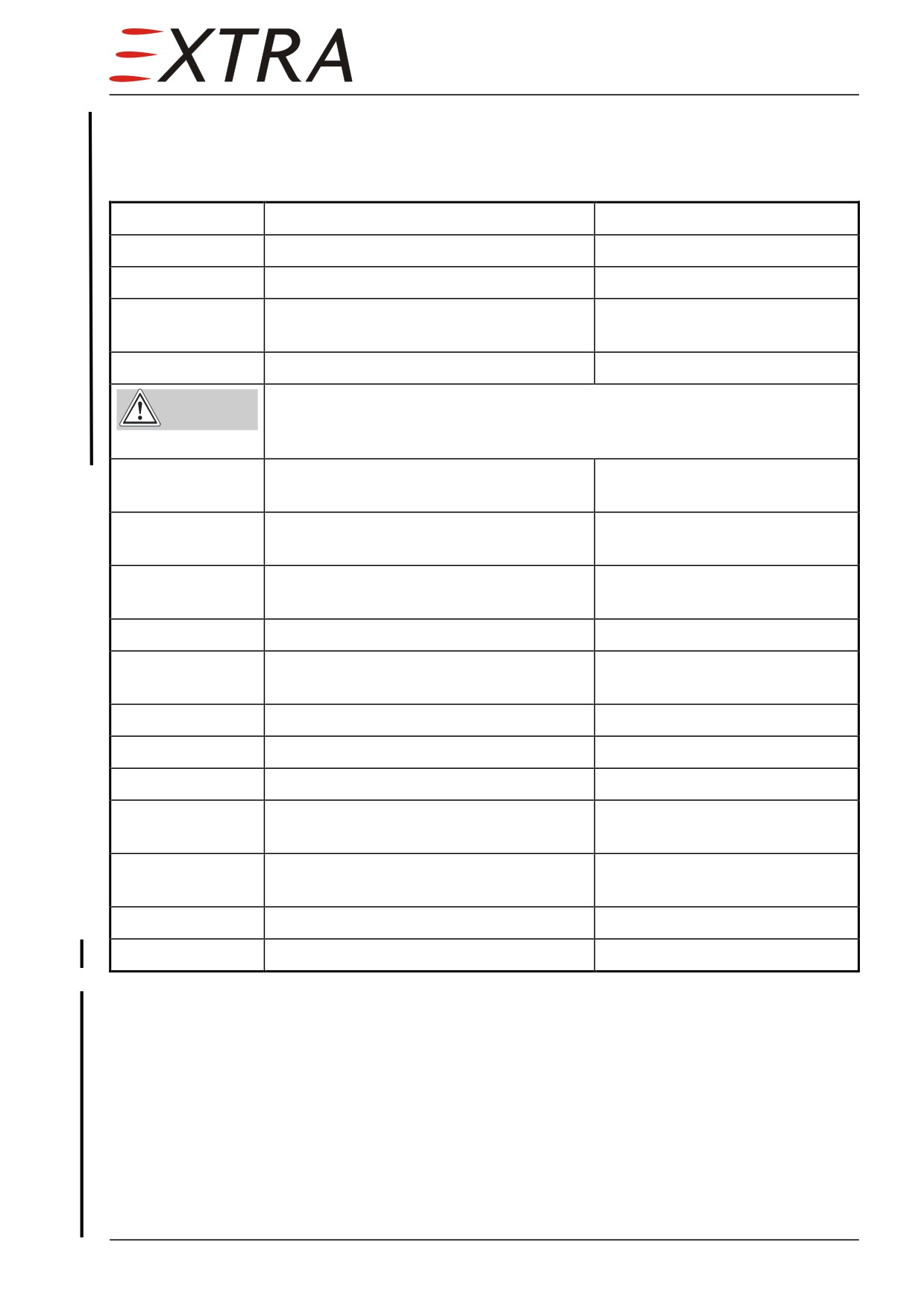
12-10-09
Main Gear Shock Absorber
Oil Draining/Refilling
Detail Steps/Work Items
Key Items
1
Place aircraft on jacks.
Refer to Chapter 07-10-00.
2
Keep landing gear down and locked.
3
Ensure BATT switch is off and no
external power attached.
4
Remove the filling nipple cover.
High-pressure oil-jet damages eyes and limbs!
WARNING
The shock absorber is under high pressure (see below).
Protect yourself when expanding the nitrogen gas-pressure.
5
Push the insert of the filling nipple to
expand the nitrogen inflation.
6
Remove the plug and O-ring from outer
cylinder.
7
Drain the hydraulic fluid completely in a
sump.
8
Replace O-rings and scraper ring.
Chapter 32-10-13
9
Refill hydraulic fluid into the cylinder.
For hydrauliuc fluid grade and
capacity see below
10
Replace the O-ring on the plug.
11
Screw the plug in the outer cylinder.
12
Lock the plug by a safety wire.
13
Connect a nitrogen charging apparatus at
the filling nipple.
14
Refill nitrogen.
Till inflation pressure as shown
below
15
Recover the cover-filling nipple.
16
Lower the aircraft.
Refer to Chapter 07-10-00.
Hydraulic Fluid Grade
Use only MILH5606 hydraulic fluid
Hydraulic Fluid Capacity
420 cm/25.6 cu in
Nitrogen Inflation Pressure
5.7 MPa / 827 psi (unloaded)
Page Date:9. August 2013
12 Page 11
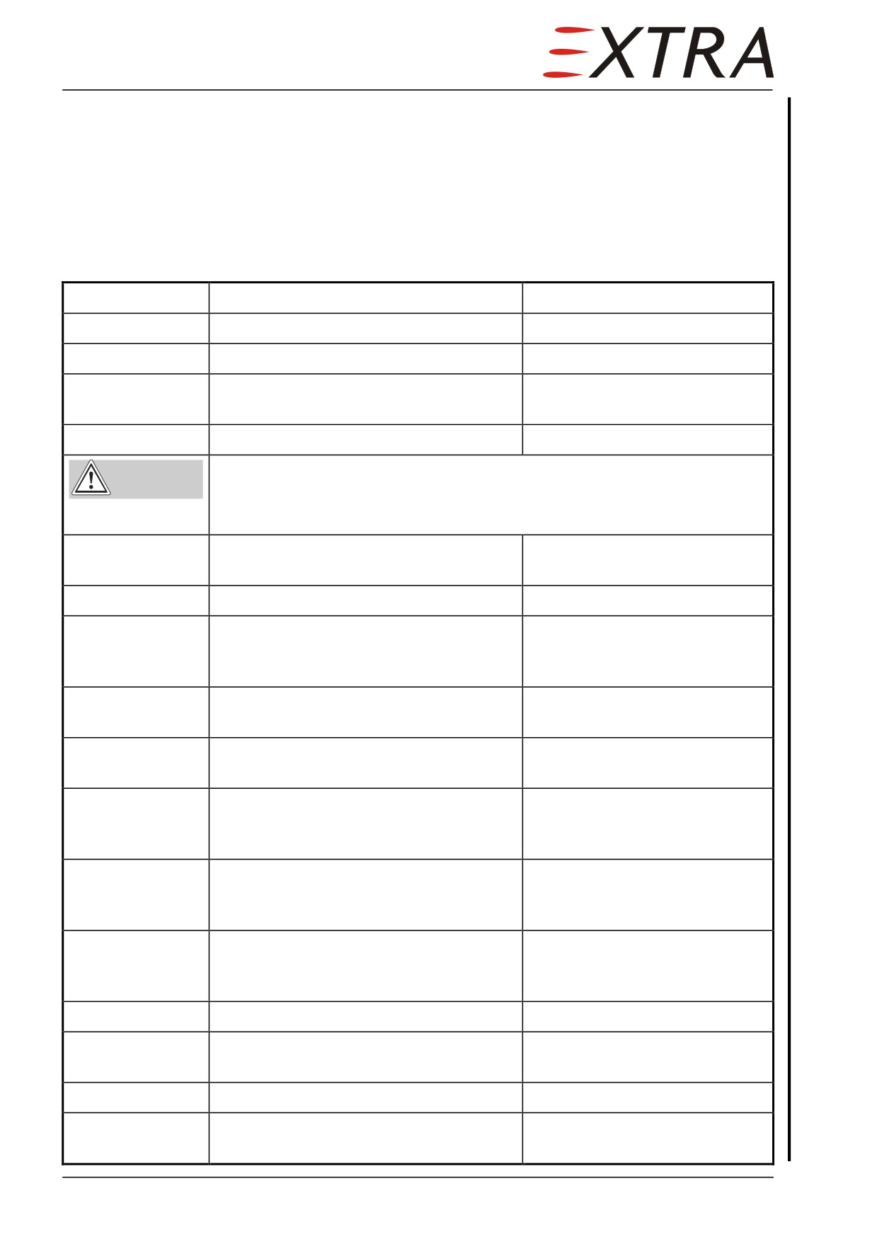
12-10-10
Nose Gear Shock Absorber
Oil Draining/Refilling
It is not possible to completely drain the nose gear shock absorber hydraulic
fluid without removal of the nose gear. However the following procedure
allows minimizing the amount of used hydraulic fluid and obtaining
a
reasonable mixing.
Detail Steps/Work Items
Key Items
1
Place aircraft on jacks.
Refer to Chapter 07-10-00.
2
Keep landing gear down and locked.
3
Ensure BATT switch is off and no
external power attached.
4
Remove the filling nipple cover.
High-pressure oil-jet damages eyes and limbs!
WARNING
The shock absorber is under high pressure (see below).
Protect yourself when expanding the nitrogen gas-pressure.
5
Push the insert of the filling nipple and
completely expand the nitrogen inflation.
6
Remove the filling nipple.
7
Drain hydraulic fluid in a sump by
completely compressing the nose gear by
hand.
8
Install a ~1.5 m transparent hose to the
nipple housing.
9
Immerse hose in a container with fresh
hydraulic fluid.
10
Slowly decompress the nose gear by hand
and thus allow hydraulic fluid to be
sucked in.
11
Repeat compression and decompression
of nose gear until hydraulic fluid is clear
and free from air bubbles.
12
Compress nose gear by hand up to
20 mm (3/4 inch) below topmost position
and hold.
13
Remove transparent hose.
14
Slowly decompress the nose gear by
hand.
15
Install filling nipple to the housing.
16
Refill nitrogen.
Till inflation pressure as shown
below.
Page 12 12
Page Date: 9. August 2013
17
Install filling nipple cover.
18
Lower the aircraft.
Refer to Chapter 07-10-00.
Hydraulic Fluid Grade
Use only MILH5606 hydraulic fluid
Hydraulic Fluid Capacity
Determined by the procedure outlined above.
Nitrogen Inflation Pressure
1.5 MPa / 218 psi (unloaded)
Page Date:9. August 2013
12 Page 13
12-20-00
SCHEDULED SERVICING
12-20-01
Exterior Cleaning
The painted surfaces of the aircraft have a long lasting, all-weather finish and
should require no buffing or rubbing out in normal conditions. However, it is
desirable to wash and polish it to preserve the outstanding exterior. Cleaning is
best accomplished with cool water, mixed with a mild aircraft detergent, if
required.
Do not use so called "mild" household detergents to wash aircraft exterior.
CAUTION
Such detergents may damage finish and corrode aluminum components.
In order to remove especially heavy dirt from the wing leading edges due to
insect splatter and the like, it is good practice to undertake cleaning
immediately after the flight, since deposits of this kind are more difficult to
remove when dry. All lubricated components are to be covered before
cleaning.
Roughly twice a year, the complete surface should be treated with a non-
silicone car polish and repolished to high gloss. But do not apply wax or use
pre-wax cleaners during initial paint curing period. Use only mild aircraft
detergent and cool water when washing exterior during the first 90 days after
repainting.
Never use cleaning agents containing silicone!
CAUTION
In order to maintain good visibility at all times, the windshield should be given
good care and kept clean at all times. Techniques and materials used to clean
glass should be avoided since acrylic glass is softer than glass and subject to
damage by solvents and abrasive glass cleaning agents.
Therefore it should be paid particular attention to using ample water applied
with clean sponges and leather, otherwise even the smallest dust particles will
tend to scratch the glazing.
Never polish acrylic glass dry!
CAUTION
Dull or scratched canopy sections can be returned to their transparent state by
treating with especially formulated acrylic glass cleaning agents.
Page 14 12
Page Date: 9. August 2013
12-20-02
Interior Cleaning
Prior to the first flight of the day it is recommended to clean the interior with a
vacuum cleaner to remove dust and loose dirt. If liquid is spilled on the cockpit
floor, blot it up promptly with cleansing tissue or rags. Continue blotting until
no more liquid is taken up.
Never use gasoline, benzine, alcohol, acetone, carbon tetrachloride, fire
CAUTION extinguisher fluid, anti-ice fluid, lacquer thinner, or glass cleaner to clean
the windshield and cabin windows. These materials will damage the
acrylic glass and may cause severe crazing.
12-20-03
Engine Cleaning
Accumulation of dirt and oil within the engine compartment creates a fire
hazard and hampers inspection. All cleaning operations have to be performed
in well ventilated work areas, and it has to be ensured that adequate fire-
fighting and safety equipment is available.
Clean the engine in accordance with the Rolls Royce
250-B17F Series
Operation and Maintenance Manual (LOAP 1). Follow the procedures given
there after performing the following preparations:
1 After running, allow the engine to cool before cleaning.
2 Protect the alternator, starter-generator, other electrical components, the air
inlets and the engine cowlings against cleaning agents.
3 Do not to start the engine before the cleaning agent has been completely
removed or has evaporated.
Page Date:
12 Page 15
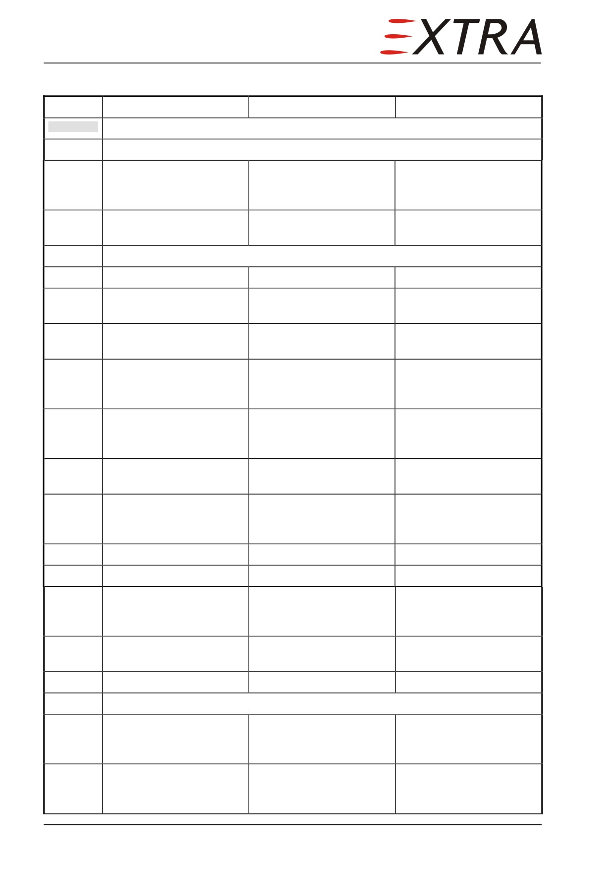
12-20-04
Lubrication Chart
Interval
Item
Location
Lubricant
CAUTION
Do not lubricate TEFLON coated bearings and rod ends
Engine Compartment
100 h
Engine Controls
Engine compartment
MIL-PRF-7870
(Throttle, Cond. Lever)
after disassembly:
Fork Ends and Bearings
MIL-PRF-81322
100 h
Engine anti-ice
Engine compartment
MIL-PRF-7808
Bowden Cable Ends
Controls
100 h
Control Shafts
Below Instrument Panel
MIL-PRF-81322
100 h
Cable Chain Coupling
Below Instrument Panel
MIL-PRF-81322
(between Control Wheels)
close to the firewall
100 h
Chain Interconnection
Below Instrument Panel
MIL-PRF-81322
(Aileron/Rudder)
close to the firewall
100 h
Pedal Bearings
Below Instrument Panel
MIL-PRF-7870
after disassembly:
MIL-PRF-81322
100 h
Control Cable Bolt
Pedal Torque Tube and
MIL-PRF-81322
Attachments
Controls/Control Surfaces
and Nose Wheel Steering
100 h
Pressure Dome Control
Cabin Pressure Dome
MIL-G-21164
Cable Bushing
100 h
Trim Tab Hinge
Elevator
MIL-PRF-7870
after disassembly:
MIL-PRF-81322
100 h
Trim Servo Chain
Tail Cone
MIL-PRF-23827
100 h
Wing Flap Tracks
Wing
MIL-PRF-81322
2000 h
Front and rear Track
Wing
MIL-PRF-81322
Rollers at middle Flap
Tracks
2000 h
Rear Track Rollers at
Wing
MIL-PRF-81322
inner Flap Tracks
100 h
Wing Flap Spindles
Wing
MIL-PRF-81322
Engine Controls
100 h
Bowden Cable Fork End
Middle Console
MIL-PRF-7870
Attachments
after disassembly:
MIL-PRF-81322
100 h
Control Lever Bearing
Middle Console
MIL-PRF-7870
after disassembly:
MIL-PRF-81322
Page 16 12
Page Date: 9. August 2013
Interval
Item
Location
Lubricant
100 h
Control Lever Guidance
Middle Console
MIL-PRF-81322
Landing Gear
100 h
Nose Gear Steering Arm
Nose Gear Steering
MIL-PRF-81322
100 h
Bearings with Lubrication
Nose and Main Gear
MIL-G-21164
Nipple
Landing Gear Doors
100 h
Upper and Lower Door
LH and RH Main Gear
MIL-PRF-7870
Hinges
after disassembly:
MIL-PRF-81322
100 h
Nose Gear Door Hinges
Nose Gear
MIL-PRF-7870
after disassembly:
MIL-PRF-81322
100 h
Rod Ends of Telescope
Nose Gear
MIL-PRF-7870
Guide Rod
after disassembly:
MIL-PRF-81322
100 h
Rod Ends of Push-Pull
Nose Gear
MIL-PRF-7870
Rods
after disassembly:
MIL-PRF-81322
100 h
Fork Ends and Universal
LH and RH Main Gear
MIL-PRF-7870
Joint of Lower Doors
after disassembly:
Actuating Mechanism
MIL-PRF-81322
100 h
Fork Ends and End Fitting
Main Gear between Keel
MIL-PRF-7870
of Lower Doors Actuating
Beams
after disassembly:
Cylinders
MIL-PRF-81322
100 h
End Fitting of Upper
Compartment in front of
MIL-PRF-7870
Doors Actuating Cylinders
Main Gear
after disassembly:
MIL-PRF-81322
Wheels and Brakes
100 h or
Wheel Bearings
Main Gear
MIL-PRF-81322
annually
100 h
Brake Guide Pins
Brakes
Copper paste
Page Date:
12 Page 17
12-30-00
UNSCHEDULED SERVICING
12-30-01
Removal of Snow and Ice
After snowfall, the snow should be removed immediately from surface of the
aircraft. Otherwise the water formed from melted snow will freeze on the
surface or in slots and gaps of fairings.
Do not use sharp tools for removing the snow.
CAUTION
If the aircraft shows signs of ice formation, it is recommended to defrost in a
room. Remove as much snow as possible with a soft bristle boom, make sure
the wheels and brakes are clear, and tow the aircraft into a room with elevated
temperature. This method is particularly desirable, since it will melt any
undetected ice and snow that could constitute a flight hazard.
Page 18 12
Page Date: 9. August 2013
Chapter 20
Standard Practices
Airframe
20 Page 1
Table of Contents
20-00-00
GENERAL
3
20-10-00
STANDARD PRACTICES AIRFRAME
....................................................... 4
20-10-01
Width Across Flats for Metric Bolts
............................................................... 4
20-10-02
Torque Values
................................................................................................... 4
20-10-04
Special Torque Values
...................................................................................... 5
20-10-05
Measuring Techniques
..................................................................................... 6
20-10-06
Coin Tapping..................................................................................................... 6
20-10-07
Flexible Hoses
.................................................................................................... 6
Replacement of Flexible Hoses
.......................................................................... 6
Installation of Flexible Hose Assemblies
........................................................... 7
20-10-08
Fittings
............................................................................................................... 7
20-10-10
Bowden Cables
.................................................................................................. 8
Inspections
.......................................................................................................... 8
20-10-11
Engine Controls
................................................................................................ 8
Figure 20-1
Engine Control Bowden Cables Schematic
...................................................... 10
20-10-12
Rod Ends
11
20-10-13
Fork Ends
........................................................................................................ 11
20-10-14
Installing Bolts to CFRP Structures
............................................................. 11
20-10-15
Connections of Lightning Protection System
............................................... 12
Page 2 20
20-00-00
GENERAL
The design of the airframe is according to standard procedures and requires no
special tools or procedures for maintenance. For that reason, only the bolts
used with the EXTRA 500 with relevant torque values and measuring
techniques are described in the following.
20 Page 3
20-10-00
STANDARD PRACTICES AIRFRAME
20-10-01
Width Across Flats for Metric Bolts
Thread diameter
Width across flats
M4
7 mm
M5
8 mm
M6
10 mm
M8
13 mm
M10
17 mm
M12
19 mm
M16
24 mm
M20
30 mm
M24
36 mm
20-10-02
Torque Values
Nuts, except of counter nuts are mainly stop nuts according to LN 9348 or
selflocking nuts according to AN 363.
a) Standard torque values allowed for bolts and nuts according to DIN and LN
must be adhered to as follows:
Metric thread size
Torque value (Nm) Torque value (in.lbs)
M4
1.8
16
M5
3.9
- 4.3
35 - 38
M6
6.2
- 6.8
55 - 60
M8
15.2
- 16.8
144 - 148
M10
29.5
- 32.5
261 - 287
M12 x 1.5
51 - 57
452 - 504
Page 4 20
b) Standard torque values allowed for bolts and nuts according to AN and MS
must be adhered to as follows:
Inch thread size
Torque value (Nm) Torque value (in.lbs)
1/4 -28
3.5
- 4.5
30 - 40
5/16 -24
6.7
- 9.5
60 - 85
3/8 -24
10.7
- 12.5
95 - 110
7/16 -20
30.5
- 33.9
270 - 300
1/2 -20
32.8
- 46.3
290 - 410
9/16 -18
58.1
- 67.8
480 - 600
IMPORTANT On all bolt connections, the specified torque and locking method must be
observed. Do not reuse stop nuts if they can be run up finger tight!
20-10-04
Special Torque Values
Special torque values for the following items must be adhered to:
Item
Torque value Torque value
(Nm)
(in.lbs)
Propeller flange bolt Mühlbauer
112
990
Bolt nose wheel tire
11
90 - 100
Bolt main wheel tire
17
150
Engine mount to fuselage
75 - 80
664 - 708
(Bolts DIN 912 M12/12.9)
Engine mount to fuselage
15.2
- 16.8
135 - 149
(Bolts LN 9037 x 08)
Engine mounting (Bolts AN 7 - 44A)
32
283
Engine shock mount
11.9
- 13.0
105 - 115
Wing bolt retaining sheets front (M5 bolts)
4
36
Wing bolts rear (M10 bolts)
16
140
Fuselage joints (M6)
6.5
57.5
Fuselage joints (M8)
16
142
Wing fittings (M8)
16
142
Wing fittings (M10)
30
265
Main gear former connection bolts (M10)
25
200
Valve cover
7
60
IMPORTANT
On all bolt connections, the specified torque and locking method must be
observed. Do not reuse stop nuts if they can be run up finger tight!
20 Page 5
20-10-05
Measuring Techniques
When using stop nuts, the safety torque (friction torque or braking torque)
should be added to the table standard values. This value is indicated on the dial
of the torquemeter, before the nut contacts the attachment surface.
Always torque nuts for fastening, if possible. When bolts are torqued there
might be an additional torque value due to shaft friction. This torque can be
determined by a torquemeter before the bolt head contacts the attachment
surface and should be added to the table value.
20-10-06
Coin Tapping
Inspection for damage is more critical for composite structure than for
conventional structures. A large washer or similar object is a valuable tool for
detecting debonds in the airframe surface. When a large washer is lightly
bounced against a solid structure, a clear metallic ring should be heard. If
delamination is present, a dull thud will be heard.
20-10-07
Flexible Hoses
The EXTRA 500 is equipped for the oil, fuel, and sensing lines with standard
"STRATOFLEX-hoses, Aerospace Connectors Division" or equivalent
"AEROQUIP-hoses, Aerospace Division", according to MIL-DTL-25579 and -
27267 specification. For the bleed air system SCEET hoses are installed. For
brake and hydraulic lines KRONTEC PTFE-Hoses 6000 are used. Maintenance
work or overhaul of these hoses requires the attention to the manufacturer's
information and bulletins.
The hoses inside the engine compartment are covered with appropriate fire
sleeves (integrated or slip-over type).
Hoses and hose assemblies should be checked for deterioration at each
inspection period. Leakage, separation of the cover or braid from the inner
tube, cracks, hardening, lack of flexibility, and excessive "cold flow" are
apparent signs of deterioration and reason for replacement. The term "cold
flow" describes the deep, permanent impressions in the hose produced by
pressure of hose clamps or supports.
Replacement of Flexible Hoses
For the replacement of hoses and hose assemblies the EXTRA should be
contacted.
Any of the following conditions require replacement of the hose assembly:
•
Fitting slippage on hose,
•
Damaged, cracked, cut or abraded cover (any reinforcement exposed);
•
Hard, stiff, heat cracked, or charred hose;
Page 6 20
•
Cracked or damaged fittings;
•
Leaks at fitting or in hose;
•
Kinked, crushed, flattened or twisted hose
•
Bent to a radius smaller than the minimum bend radius
•
Blistered, soft, degraded, or loose cover.
The entire assembly must be replaced, if failure occurs in a flexible hose
assembly. Obtain a new hose assembly of the correct size and length, complete
with factory-installed end fittings.
Installation of Flexible Hose Assemblies
External forces can significantly reduce hose life or cause failure. Mechanical
loads which must be considered include tensile or side loads and vibration.
In general hose assemblies should be handled with care to prevent excessive
bending, twisting and kinking. Particular attention must be given to preclude
hoses from wear, snagging, kinking, bending smaller that minimum bend
radius and cutting, any of which can cause premature hose failure.
The minimum bend radius for flexible hoses varies according to size and
construction of the hose and the pressure under which the hose is to operate.
Bends that are too sharp will reduce the bursting pressure of flexible hose
considerably below its rated value.
Large diameter hoses and very short hose assemblies are more prone to
kinking. Twisting of the hose can be determined from the identification
markings running along its length.
The flexible hose should be installed so that it will be subject to a minimum of
flexing during operation.
20-10-08
Fittings
For the oil, fuel, bleed air, and brake system only AN-fittings are used in the
EXTRA 500. In some areas of the hydraulic system special fittings are used
(metric thread).
For the assembly of PTFE-hoses and reusable fittings follow the standard
practices for such combinations.
All these fittings are made of aluminum alloy or stainless steel and are blue-
colored or clear for identification purposes. The dash number following the AN
number indicates the size of the hose for which the fitting is made, in 16ths of
an inch. This size measures the inner diameter (I.D.) of the hose. The material
code letter (Aluminum alloy: code D) follows the dash number.
Example:
Elbow AN 822-8D
NOTE
Clean removed fittings from sealing, sealing tape, etc. and apply
FUELUBE on the thread before installation (except ventilation system).
Don't use sealing tape for sealing.
20 Page 7
20-10-10
Bowden Cables
Bowden cables are used for the following systems of the EXTRA 500:
•
Engine Controls (High performance Push-pull Bowden cable, stainless steel)
•
Air Inlet Heating (Button lock dash control, solid wire end)
•
Parking Brake (Ratchet control, solid wire end)
•
Windshield Heating (solid wire end)
•
Trim Control (Special TLS III cable system)
Minimum bend radius: 65 mm.
Refer to Triumph Controls Germany GmbH Installation Instructions TLE10
(LOAP 36)
•
Seat adjustment locking mechanism
•
Aft passenger seat back rest swivel mechanism
Inspections
Observe the following hints when performing inspections on the Bowden
cables:
A cable must be replaced whenever:
•
excessive free play is felt at the control even after all cable connections have
been verified as in good working order.
•
visual inspection shows chafing, breakage or bent, loose or worn parts.
•
evidence of moisture is found inside (or Bowden cable has frozen).
•
a gradual or sudden decrease in the stroke (travel) length of the Bowden cable
has been detected.
•
a gradual or sudden increase in the no-load (cable free and unattached) friction
of a Bowden cable has been detected.
Correct routing of the Bowden cable whenever:
•
misalignment, unacceptable high internal friction due to bends below minimum
radius or malfunction of sliding elements has been detected.
•
the usable stroke is not centered within the available travel.
•
the swivel angle is not centered within the available angle (if applicable).
20-10-11
Engine Controls
Consider the following information when working on engine Bowden cables.
Refer to Figure 20-1:
Hard and abrupt control inputs may impose high dynamic peak loads to the
related sliding parts at reaching the travel stops.
A bent swivel sleeve as well as wear and excessive free play at the pivot
(swivel) points and sliding parts are an indication of misalignment and/or hard
Page 8 20
and abrupt control inputs. Those signs should be found early within the regular
maintenance. This is a clear indication of an unacceptable Bowden cable
condition, which might result in a malfunction.
As soon as a Bowden cable becomes difficult to operate, the reason should be
identified. An increase in no-load (cable free and unattached) friction or an
increase in travel length of a Bowden cable are a good indication of pending
performance problems and/or Bowden cable failure.
The following notes, cautions and warnings describe application and
installation information:
Protect the cable from contaminants such as fuel, oil, water, dirt and
CAUTION
chemicals, which may damage the Bowden cable.
Protect the cable from physical damage by paint, kinking, vibration, etc.,
which may damage the Bowden cable.
IMPORTANT
A gradual or sudden increase in the no-load (cable free and unattached)
friction of a Bowden cable is a good indication of pending performance
problems and/or Bowden cable failure. Serious injury or death may result.
Replacement is required.
A gradual or sudden decrease in the stroke (travel) length of the Bowden
cable is a good indication of pending performance problems and/or
Bowden cable failure. Serious injury or death may result. Replacement is
required.
Bowden cables, which have moisture inside of them or have frozen, must
be replaced. Do not apply heat to attempt to remove the moisture.
Applying heat will not remove the moisture. Serious injury or death may
result. Replacement is required.
NOTES
Installation should be accomplished by a licensed “A” and/or “P”
mechanic.
Bowden cables are designed to be non-repairable. Do not perform any
repairs to this Bowden cable.
Cables are designed to be contaminant resistant; not contaminant proof.
The usable stroke must be centered within the available travel.
The swivel angle must be centered within the available swivel angle.
The minimum bend radius is 4".
Bowden cables are lubricated for the life of the Bowden cable. Do not
remove the seals or lubricate the Bowden cable.
20 Page 9
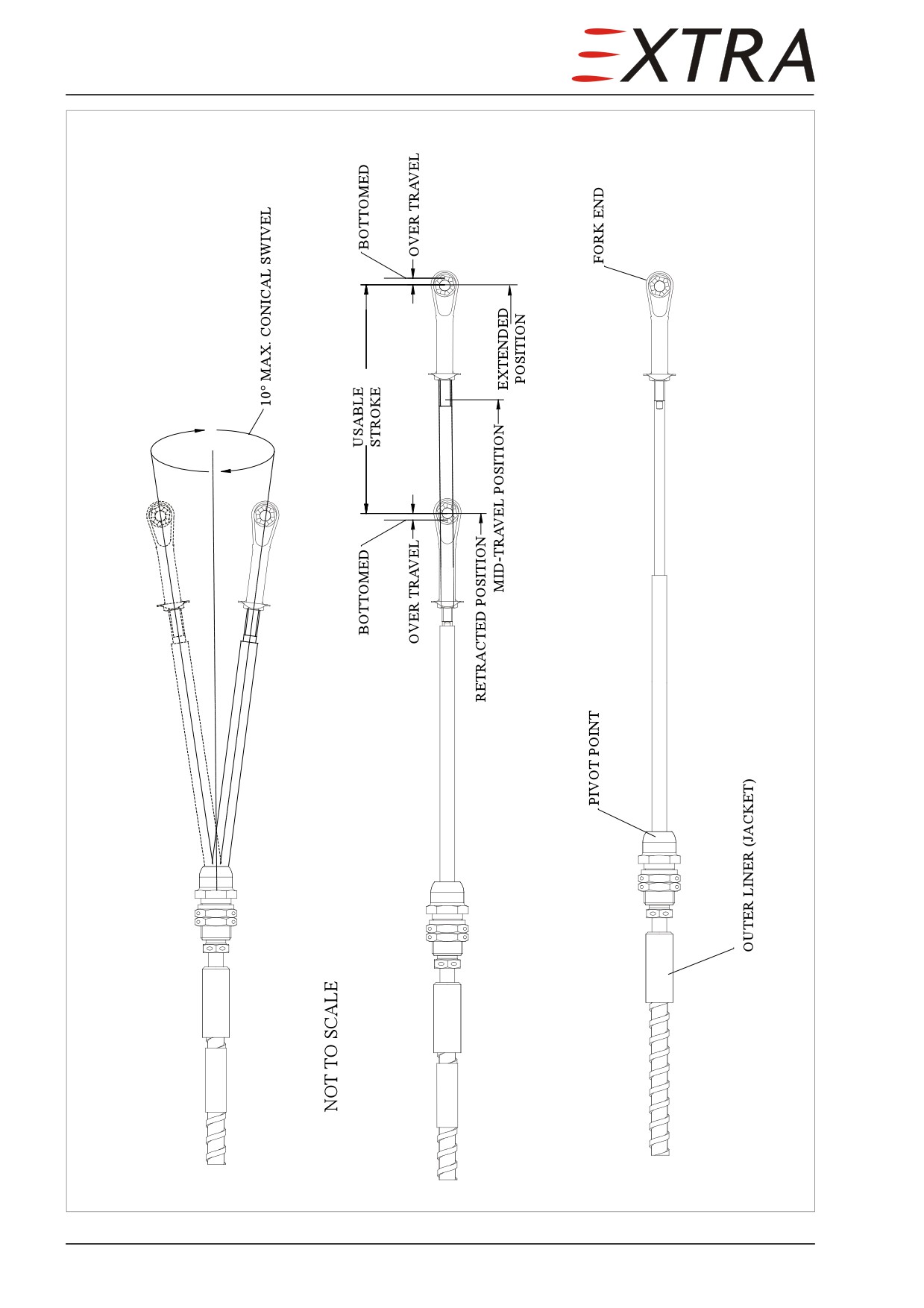
Figure 20-1
Engine Control Bowden Cables Schematic
Page 10 20
20-10-12
Rod Ends
Two different kinds of rod ends are used for the EXTRA 500:
• Teflon coated
• stainless steel
The Teflon coated rod ends have to be installed dry and require no
maintenance.
The stainless steel rod ends and attachment bolts shall be lubricated with MIL-
G-81322 (Aeroshell Grease 22c) when newly installed or reinstalled. For
lubrication during scheduled maintenance
(without removal/reinstallation)
MIL-PRF-7870 shall be used.
20-10-13
Fork Ends
Generally fork ends and attachment bolts shall be lubricated with MIL-G-
81322
(Aeroshell Grease
22c) when newly installed or reinstalled. For
lubrication during scheduled maintenance
(without removal/reinstallation)
MIL-PRF-7870 shall be used.
20-10-14
Installing Bolts to CFRP Structures
To avoid electrochemical corrosion all non-stainless bolts and screws must be
sealed independent from their surface protection. This does not apply to
corrosion resistant steel (CRES).
Detail Steps/Work Items
Key Items
1
Remove old sealant.
2
Install bolts with epoxy resin.
Hardening as per
manufacturer information
PR 1750 accelerator contains harmful vapors and is readily absorbed
WARNING
through the skin.
Avoid all contact with the skin and ingestion.
Always wash hands before eating or smoking.
Use adequate ventilation, hand protection and chemical-type goggles
when working with this product.
If accelerator contacts skin, flush area with warm water. Obtain medical
attention in cases of extreme exposure or ingestion.
20 Page 11
Detail Steps/Work Items
Key Items
PR 1750 sealant contains solvents.
WARNING
Use adequate ventilation or air-supplied respirators during application.
Avoid repeated or prolonged breathing of vapors.
In case of extreme vapor exposure, remove affected personnel to fresh
air immediately and obtain medical attention.
For complete health and safety information, a refer to Le Joint Francais
Material Safety Data Sheet PR 1750 (LOAP 41)
3
After final torquing apply PR 1750 sealant
For mixing and application of
to both the head and nut side of the bolt
PR 1750 sealant refer to
including washer and thread end.
manufacturer's instructions.
20-10-15
Connections of Lightning Protection System
Prior to joining or riveting prepare contact surfaces as follows:
Material
Action
Aluminum
Remove oxide film
Steel
Remove paint
Stainless steel
Degrease
Titanium
Degrease
After connection of parts seal gaps and connecting elements from all sides to
avoid ingression of moisture:
Connection
Action
Aluminum - Steel
Apply PR 1750A
All other
Apply Nycote 7-11
Page 12 20
Chapter 21
Air Conditioning
21 Page 1
Table of Contents
21-00-00
DESCRIPTION
5
Troubleshooting
.................................................................................................. 7
Bleed Air System Leak Test
............................................................................... 8
Cabin Leak Test
.................................................................................................. 9
Dump Test
10
21-00-01
Sceet Hoses
12
Replacement
12
21-10-00
COMPRESSION
13
Description
13
21-10-01
Primary Shut-off Valve
13
Removal/Installation
13
21-10-02
Mass Flow Control Valve
14
Removal/Installation
14
21-10-03
Mass Flow Sensor
14
Removal/Installation
14
Check
14
21-10-04
Mass Flow Controller
15
Removal/Installation
15
21-10-05
Muffler
15
Removal/Installation
15
21-20-00
DISTRIBUTION
16
Description
16
21-20-01
Panel Vent Fans
16
Removal/Installation
16
21-30-00
PRESSURIZATION CONTROL
18
Description
18
Operation
18
21-30-01
Cabin Outflow Control Valve Filter
21
Replacement
21
21-30-02
Cabin Outflow Control Valve
21
Removal/Installation
21
21-30-03
Safety Valve
22
Removal/Installation
22
21-50-00
COOLING
23
Description
23
Service and Maintenance
23
Page 2 21
Page Date:
21-50-01
Compressor/Condenser
..................................................................................24
Removal/Installation
.........................................................................................24
21-50-02
Evaporator
.......................................................................................................24
Removal/Installation
.........................................................................................24
21-50-03
Soft Start Module
............................................................................................25
Removal/Installation
.........................................................................................25
21-60-00
TEMPERATURE CONTROL
26
Description
........................................................................................................26
21-60-01
Temperature Switch........................................................................................27
Removal/Installation
.........................................................................................27
Function Test
.....................................................................................................27
21-60-02
Duct Temperature Sensor
..............................................................................28
Removal/Installation
.........................................................................................28
21-60-03
Cabin Temperature Sensor
............................................................................28
Removal/Installation
.........................................................................................28
21-60-04
Temperature Controller
.................................................................................29
Removal/Installation
.........................................................................................29
Page Date:
21 Page 3
21-00-00
DESCRIPTION
Refer to Figure 21-1.
The following systems are installed in the EXTRA 500 to cope with the
various tasks of air conditioning:
•
Bleed air system with mass flow control
•
Ram air system
•
Distribution system
•
Pressurization system
•
Temperature regulation system
•
Cooling system
For ventilation either ram or pressurized (bleed) air is used. Before entering the
cabin bleed air is mass flow controlled and temperature can be modified by the
temperature regulation. The airflow is then ducted to the legroom and/or to the
windshield. The cabin air additionally can be cooled by the cooling system.
Pressurization is done by the bleed air system in combination with a
controllable outflow valve.
Generally air is routed through SCEET hoses. On some locations T- or Y-
distributors are connected to the hoses with worm drive hose clamps.
21 Page 5
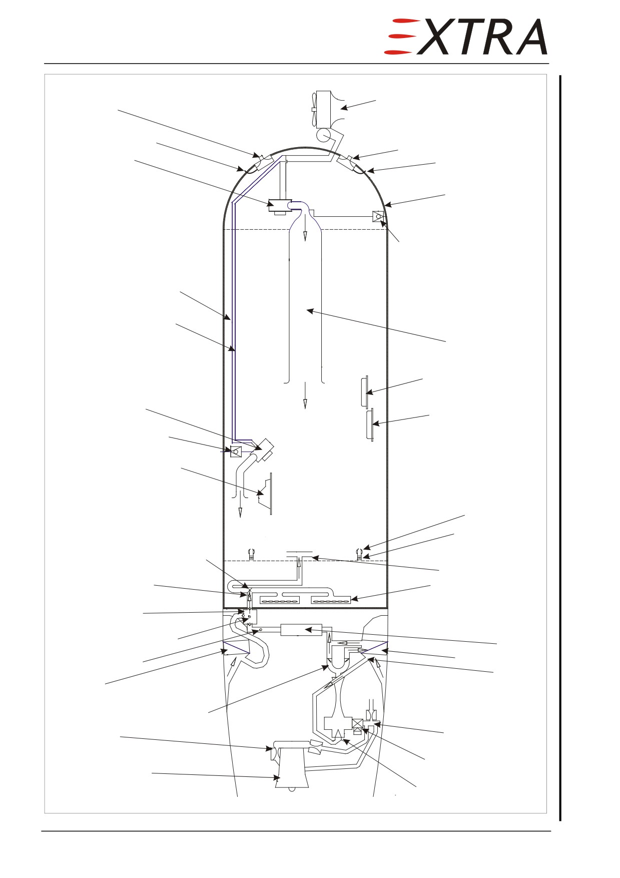
Compressure/condenser module
Safety valve
Static reference port
Cabin control outflow valve
Evaporator (aft)
Static reference port
Aft pressure dome
Evaporator drain float valve
High pressure refrigerant
(isolated)
Low pressure refrigerant
(return flow)
Overhead channel
Temperature controller
Evaporator (front)
Mass flow controller
Evaporator drain valve
Cabin temperature sensor
Panel vent fan
Panel vent outlet
Defog/cabin distribution valve
Legroom dispenser
Temperature switch
Windshield dispenser
Cabin inflow box
Pressure bulkhead and firewall
with check valves
Duct temperature sensor
Muffler
Mass flow sensor
Air-to-air cooler
Air Inlet
Oil cooler
Temperature modulating valve
Bleed air manifold
Sonic venturi
Primary shut-off valve
Engine compressor
Mass flow control valve
Figure 21-1
Cabin Air Condition and Pressurization Scheme
Page 6 21
Page Date:
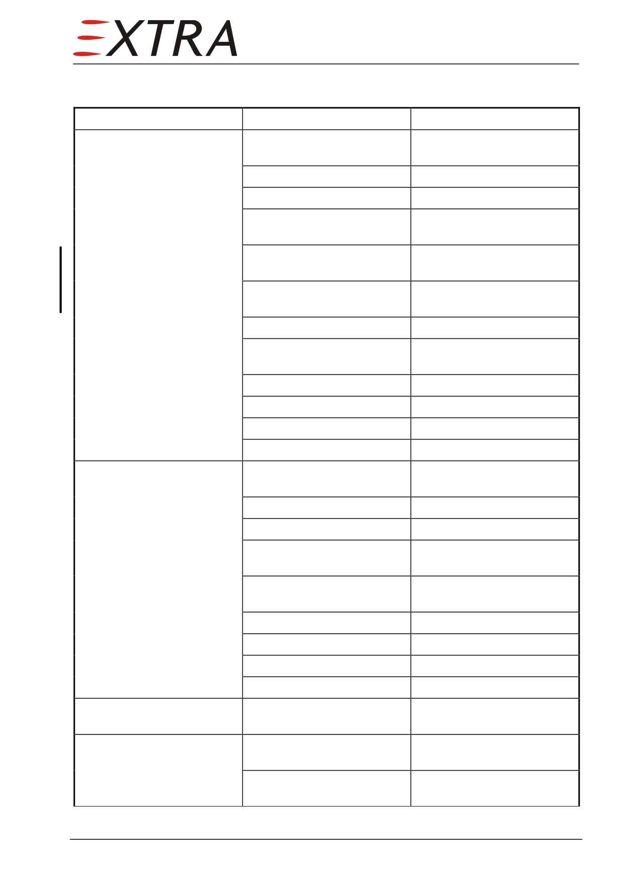
Troubleshooting
Complaint
Possible Cause
Remedy
No or inadequate
Pressurization system inactive
Switch pressurization system
pressurization
ON
Excessive cabin leakage
Identify and seal
Excessive door seal leakage
Replace door seal
Excessive emergency exit seal
Replace emergency exit seal
leakage
Bleed air system leakage
Perform Bleed Air System
Leak Test procedure
Dump solenoid energized
Check dump switch and squat
(safety valve open)
switch
Pressure controller failure
Replace controller
Cabin control outflow valve
Replace control outflow valve
failure
Safety valve failure
Replace safety valve
Mass flow sensor failure
Replace mass flow sensor
Mass flow valve failure
Replace mass flow valve
Mass flow controller failure
Replace mass flow controller
Incorrect pressurization or
Pressurization system inactive
Switch pressurization system
pressurization rate control
ON
Bleed air system leakage
Identify and seal
Pneumatic system leakage
Identify and seal
Cabin control outflow valve
Clean static reference
static reference blocked
connection
Cabin control outflow valve
Replace filter
filter blocked
Pressure controller defective
Replace controller
Mass flow sensor failure
Replace mass flow sensor
Mass flow valve failure
Replace mass flow valve
Mass flow controller failure
Replace mass flow controller
Incorrect pressurization or
Cabin control outflow valve
Replace control valve
pressurization rate control
defective
Pressure differential exceeding
Cabin control outflow valve
Clean static reference
5.5 psi
static reference blocked
connection
Cabin control outflow valve
Replace control valve
differential failure
Page Date:
21 Page 7
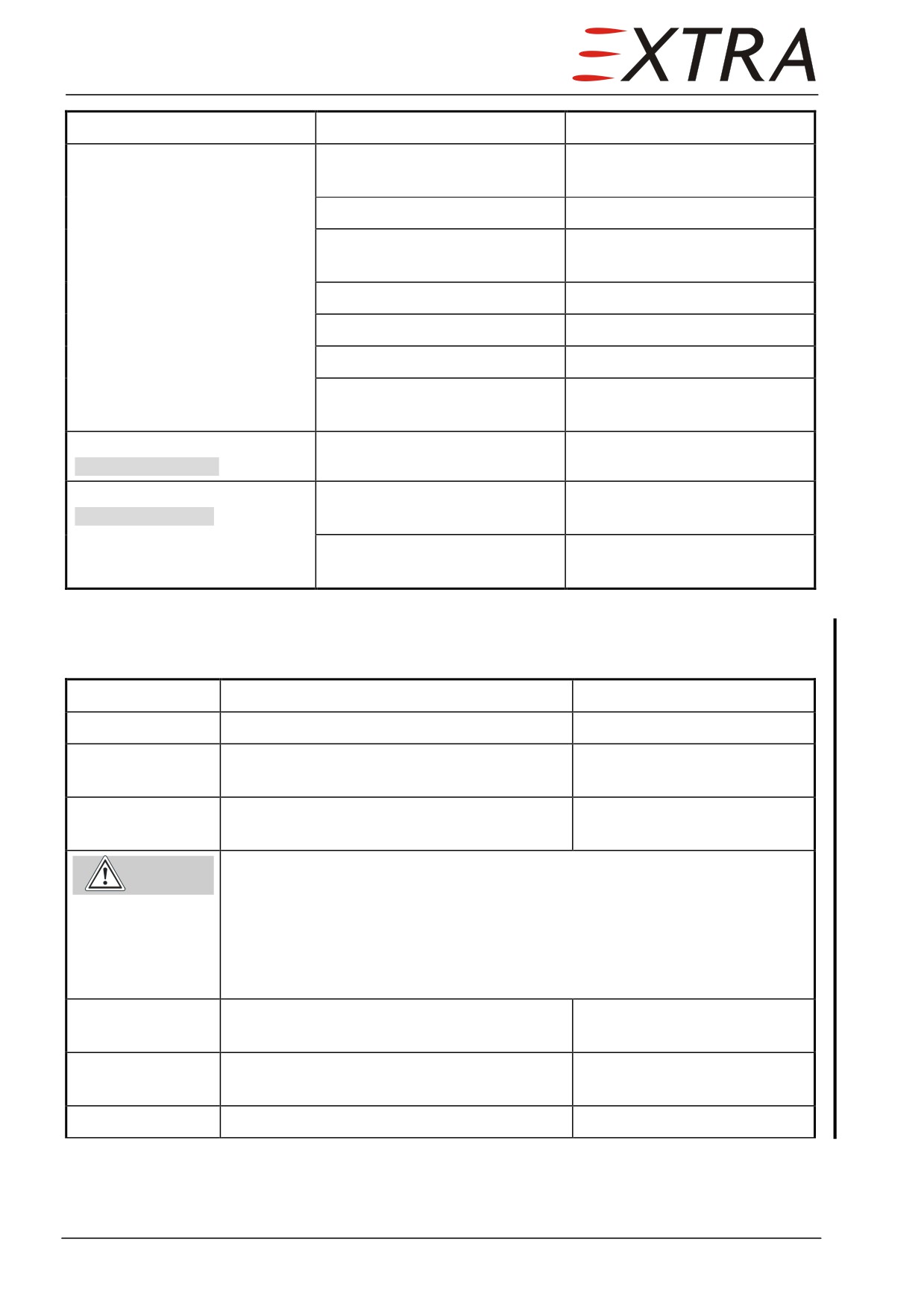
Complaint
Possible Cause
Remedy
No dump
Pressurization system inactive
Switch pressurization system
ON
Squat switch setting incorrect
Correct squat switch setting
Safety valve static reference
Clean static reference
blocked
connection
Dump switch defective
Replace dump switch
Squat switch defective
Replace squat switch
Safety valve solenoid failure
Replace safety valve
Safety valve blind plug at
Install blind plug
vacuum port not installed
Erroneous warning
Temperature switch defective
Replace temperature switch
BLEED OVERTEMP
Erroneous warning
Differential pressure switch
Replace differential pressure
CABIN PRESSURE
(5.65 psig) defective
switch
Absolute pressure switch
Replace absolute pressure
(10,000 ft) defective
switch
Bleed Air System Leak Test
Refer to Figure 21-1.
Detail Steps/Work Items
Key Items
1
Remove both upper engine cowlings.
Refer to Ch. 71-10-01/02.
2
Remove bleed air hose from cabin inflow
box.
3
Install a cabin pressurization unit or
equivalent to the bleed air hose.
Risk of injury due to flying parts when pressurizing the bleed air
Warning
system.
Follow cabin pressurization unit safety instructions before installing the
unit.
Apply Max. 5.5 psig air to the bleed air system.
Protect your eyes with safety glasses.
4
Inspect bleed air system for leaks using leak
Seal or replace parts if
detection spray.
necessary.
5
Reinstall bleed air hose to the cabin inflow
box.
6
Reinstall both upper engine cowlings.
Refer to Ch. 71-10-01/02.
Page 8 21
Page Date: