Extra 500. Maintenance Manual (2012) - page 2
Time Limits and Maintenance Checks
05-00-02
Words with Special Meanings
In this Maintenance Manual, the words that follow have special meanings :
Adjust
To put to a specified position or condition. For example, adjust the clearance
to 1 mm.
Check
A technical name for a group of maintenance tasks. For example,
the 100 hour check.
Examine
To look carefully at an item. It includes steps such as these:
Make sure that the item:
1
Is complete.
2
Is correctly attached.
3
Has no loose parts.
4
Shows no signs of leaks.
5
Is not cracked or damaged.
6
Is not worn.
Make sure that:
1
The surface protection is not damaged.
2
All locking devices are installed correctly.
Make sure that items such as pipes and cables (see also Chapter 20-10-09):
1
Look serviceable.
2
Do not rub against other items (chafing marks).
Inspection
The procedure, which compares an object with its standard or specification.
Measure
To find out the dimensions, capacity or quantity of something.
Monitor
To look at something during a time. For example, monitor the engine speed
indicator.
Record
Technical name for something that shows what was done. For example, write
the result of the test in the engine record.
Replace
To remove an unserviceable item and install a serviceable item in the same
location.
Set
To put equipment into a given adjustment, condition or mode. For example,
set the altimeter scale to 1013 mbar.
Task
An assigned work or procedure. For example, each step of the task has an
identification letter.
Test
That what you do when you operate or examine an item to make sure that it
agrees with the applicable specifications. For example, disconnect the
systems, which are not necessary for the test.
Page 6 05
Page Date:
Time Limits and Maintenance Checks
05-10-00
TIME LIMITS
05-10-01
General
Various equipment and components of the aircraft (e.g. engine, propeller) are
only cleared for a certain time of operation. After the permissible time of
operation has expired they have to be replaced or overhauled (TBO - Time
Between Overhaul). The respective TBO intervals are listed in the aircraft
record sheets.
For monitoring the permissible time of operation, this time should also be
entered into the aircraft records when removing and installing such a part
including full part and serial numbers.
05-10-02
Certification Authorities
The time limits given in this chapter are recommended by the manufacturer.
These time limits may be superseded by the regulatory authority.
05-10-03
Scheduled Maintenance Time Limits
The following components listed in Chapter 05-14-00 have to be overhauled,
replaced or inspected periodically, i.e. within fixed calendar periods or after
appearance of a certain amount of flight hours. Do scheduled maintenance at
these times:
Scheduled Maintenance
Do at these times
100 hours check
At 100 FH. Or 100 hours after the last 100
hours or larger check. Tolerance +/- 10 hours.
1000 hours check
At 1000 FH. Or 100 hours after the last 100
hours or larger check. Tolerance +/- 10 hours.
In addition scheduled engine maintenance according to Rolls Royce 250-B17F
Series Operation and Maintenance Manual (LOAP 1) has to be performed at
the time intervals given there.
05 Page 7
Time Limits and Maintenance Checks
05-10-04
Component Time Limits
Time Between Overhaul
These components have a TBO - Time Between Overhaul:
Components
Time Between Overhaul
Turboprop Engine Rolls
Refer to the latest Rolls Royce 250-B17F
Royce 250-B17F/2.
Series Operation and Maintenance Manual
(LOAP 1)
Engine accessories.
Refer to the latest Rolls Royce 250-B17F
Series Operation and Maintenance Manual
(LOAP 1)
Propeller Governors
Refer to the latest Rolls Royce 250-B17F
Series Operation and Maintenance Manual
(LOAP 1)
Aircraft Parts Corps 200SGL Every 1000 hours.
Starter Generator
BC410 Stand-by Alternator
Every 1700 hours
system
Passenger seat belt webbing. After 12 years.
MT-Propeller
Refer to the latest MT-Propeller Service
MTV-5-1-D-C-F-R(A)
Bulletin (LOAP 5).
CFR210-56.
Time Between Replacement
Replace these components at the times shown:
Components
Time Between Replacement
Purolator Facet
200 hours or 6 months which ever comes
Scavenge lube oil filter
first
Pierburg
2000 hours
Motive flow fuel pump
Integral Hydraulic
10 years
Hydraulic accumulator
Rubber type hoses
First 7, then 5 years.
wing fuel tank pick up to
fuselage connection
and
within wing fuel tank of SN
1002 and 1003
Page 8 05
Page Date:
Time Limits and Maintenance Checks
Components
Time Between Replacement
Batteries of Emergency
Every 2 years during shelf or service life, or
Locator Transmitter (ELT).
after 1 hour of cumulative use (e.g. testing),
or after operation in an emergency situation,
or before battery replacement date.
Battery replacement date is marked on the
battery pack and the label at the end of
transmitter.
For battery replacement see ARTEX
Description, Operation, Installation and
Maintenance Manual for the ME406 ELT
(LOAP 30)
Batteries of emergency torch.
Annually or after each use.
Annunciator panel
If any one lamp fails, defective lamp must
(Westcoast Specialties)
be replaced.
Annunciator panel
If any one LED fails, the unit must be
(EXTRA)
repaired or replaced.
Windows
If cracks are detected
Time Between Inspection
Inspect these equipment items at the times shown:
Components
Time Between Inspection
Battery
Refer to CONCORDE Component
Maintenance Manual (LOAP 27)
Static pressure system.
Every 2 years in accordance with 14 CFR
Ch. 1 Part 43 App. E.
ATC transponder.
Every 12 months in accordance with 14
CFR Ch. 1 Part 43 Apps. F Par. C and F.
Page Date:
05 Page 9
Time Limits and Maintenance Checks
05-20-00
SCHEDULED MAINTENANCE CHECKS
05-20-01
General
Regular inspections must be carried out every 100 or 1000 operating hours.
Annual inspections
(ANI) must be performed according to the national
requirements.
NOTE
The scope of an Annual Inspection and a 100 hour inspection is the same.
However, the manufacturer may recommend to perform additional
checks in the course of an Annual Inspection. If applicable, these checks
are identified in the Maintenance Check Schedule with the abbreviation
"ANI".
All inspections must be executed by a designated representative of the Aviation
Authority of the country in which the aircraft is registered.
05-20-02
Maintenance Checks Schedule
The maintenance and control work given in the following tables has to be
carried out within the given time intervals. The proper execution of the checks
and maintenance actions has to be certified in the maintenance records and log
books.
Faults as well as their repairs have to be entered in an inspection report filed
together with the check list in the aircraft records.
Page 10 05
Page Date:
Time Limits and Maintenance Checks
05-20-03
Scheduled Maintenance Charts
The maintenance checks described in this section include all the scheduled
checks, which must be performed. Maintenance checks must be accomplished
in accordance with CFR 14 P 43 App. D.
Use the following schedule and the lubrication charts presented in Chapter 12-
20-04.
Prior to inspection, the aircraft and engine should be thoroughly cleaned, all
inspection panels, access doors or fairings should be removed.
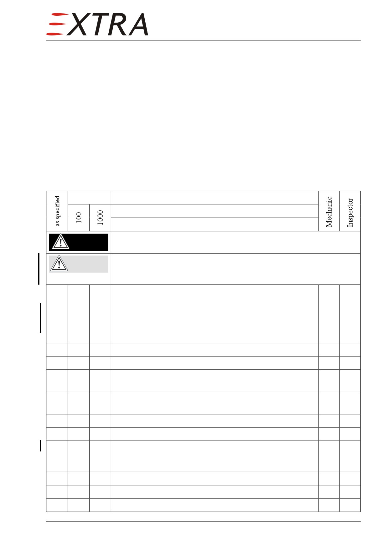
Operational Checks
Flight Hours
Date:
Serial No.:
Description:
Rotating propeller can cause death or severe injuries!
DANGER
Do not allow anyone to stay in the propeller area.
Risk of propeller shaft bending due to wind forces.
CAUTION
High power ground runs are only permitted with aircraft nose turned
into wind.
Perform an inspection operational run-up. Refer to the latest
Rolls Royce 250-B17F Series Operation and Maintenance
Manual (LOAP 1), Ch. 72-00-00, ENGINE-
X
X
ADJUSTMENT/TEST, Check Run, Operating Instructions &
Check Run Schedule. Record and verify the engine operating
parameters. Check the following items while engine is running.
X
X
Check the parking brake and toe brakes.
X
X
Check the fuel flow, fuel pressure and fuel quantity indication.
X
X
Check the function of fuel pumps by monitoring fuel pressure
indication when running a single pump.
X
X
Check fuel selector valve for proper operation and pointer
indication.
X
X
Check the oil pressure and oil temperature.
X
X
Check the generator output.
X
X
Reduce system electrical load to approx. 10 thru 15 A.
Check the stand-by alternator output with generator off.
Then generator on.
X
X
Check the cabin pressurizing operation.
X
X
Check the air condition operation.
X
X
Check the de-ice system operation.
Page Date:
05 Page 11
Time Limits and Maintenance Checks
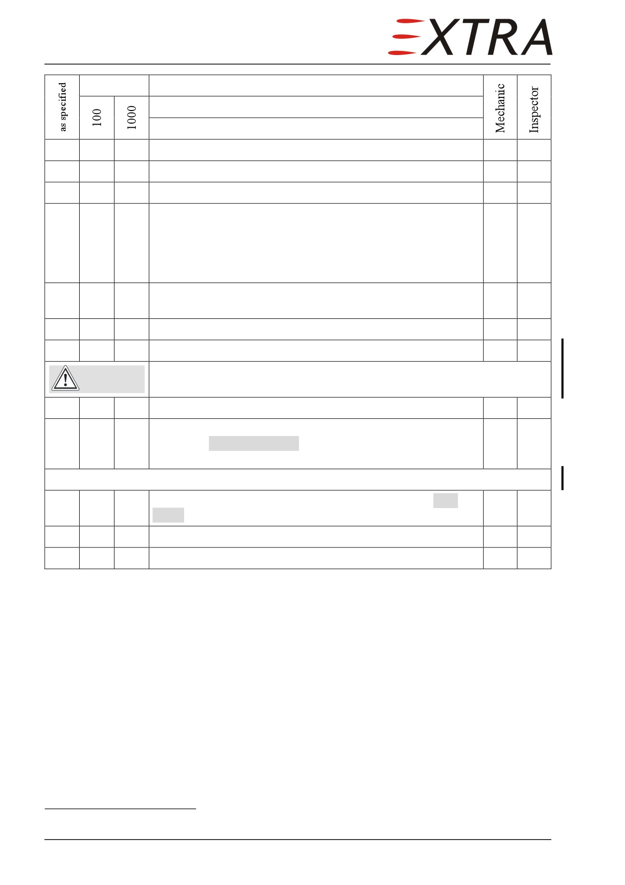
Flight Hours
Date:
Serial No.:
Description:
X
X
Check the windshield heater operation.
X
X
Check flight idle speed (N1: 65%).
X
X
Check response of the engine by power setting changes.
X
X
Check the propeller overspeed governor at 1800 RPM (N2
RPM) by pressing ENGINE OVSPD TEST button switch.
Monitor RPM drop. After release of the ENGINE OVSPD TEST
button switch Prop RPM should return to the above setting.
Then return to idle.
X
X
Check temperature regulation. Actuate WARM/COOL switch in
manual mode and check response. Return to automatic mode.
X
X
Check the annunciator light panel.
1
Check the radio and the other electronic equipment.
Risk of damage to flaps or upper door.
CAUTION
Function test of flaps only with upper door closed.
X
X
Check operation of controls and flaps.
X
X
Shut down engine. Condition lever at cut-off position. Check
immediate PNEUMATIC LOW annunciation and interruption of
cabin heat air flow. (bleed air distribution valves function check)
X
X
Change power lever position and check illumination of LOW
PITCH annunciator light.
X
X
Check the generator/alternator warning light or ammeter.
X
X
BATT switch OFF.
1 according to national regulations
Page 12 05
Page Date:
Time Limits and Maintenance Checks
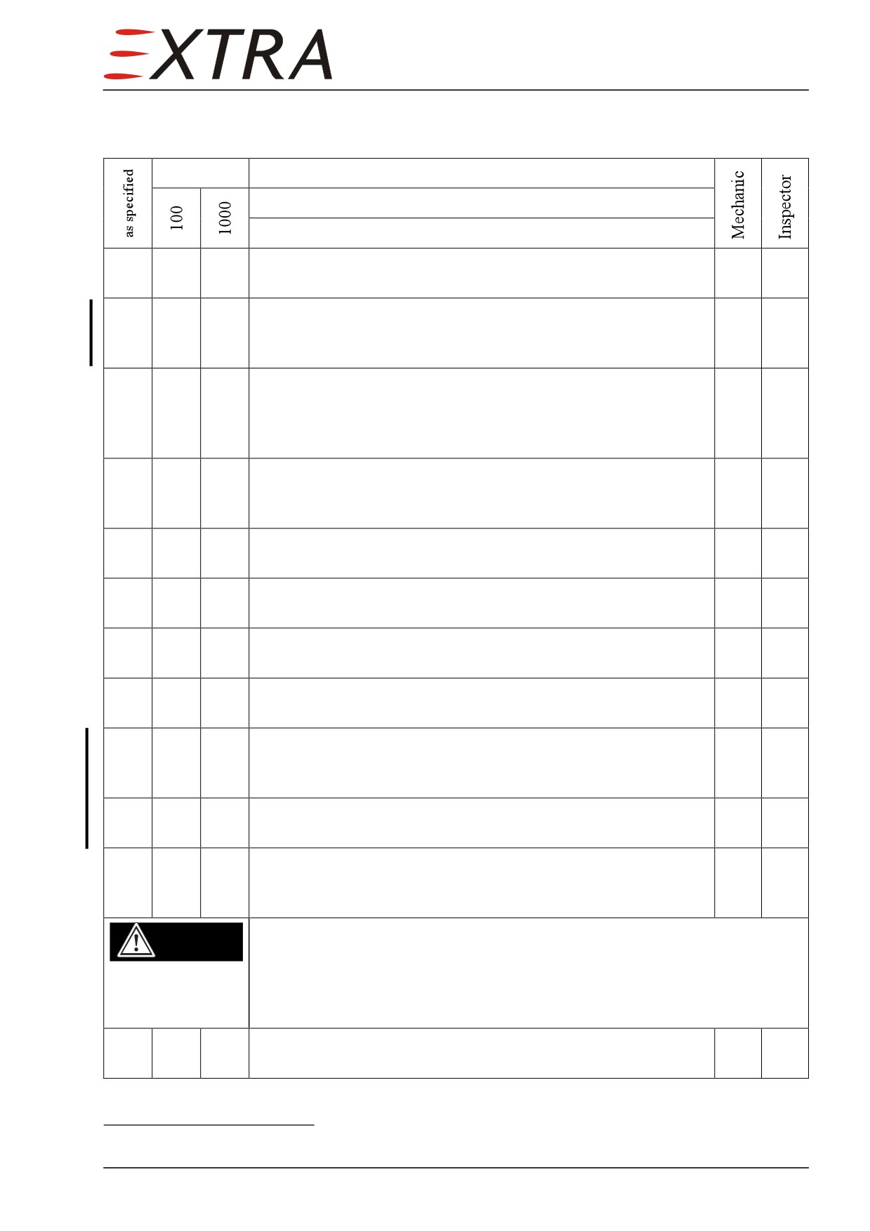
Miscellaneous
Flight Hours
Date:
Serial No.:
Description:
Clean and inspect the cowling intakes and outlets for damage,
X
X
cracks, distortion and overheat areas.
Clean fire protective coating of oil cooler inlet & outlet duct. If
X
X
necessary repaint and add clear coat (refer to Chapter 51-30-01
Fire Protective Coating).
Inspect engine mount for cracks, corrosion, looseness of
mountings and overheated areas. Inspect engine shock mount
X
X
isolators for deterioration, improper assembly and insecurity.
Replace as required.
Inspect engine controls for security, defects, improper travel
X
X
and improper safetying. Lubricate as per Chapter 12-20-04
Lubrication Chart.
Inspect engine bonding for improper installation and poor
X
X
condition.
Inspect firewall and seals for improper condition, insecurity
X
X
and improper fire resistant sealing.
Inspect battery and attachment for corrosion, etching, poor
X
X
condition and insecurity. (Charge battery if required.)
Inspect battery ventilation hose and attachment for chafing,
X
X
leakage, poor condition and insecurity.
1
Perform battery capacity test according to CONCORDE
Component Maintenance Manual (LOAP 27), Capacity Test
Procedure.
Inspect external power supply receptacle and fuses for
X
X
cleanliness, corrosion, poor condition and insecurity.
Inspect electrical leads, lines, ceramics and attaching for
X
X
chafing, deterioration, improper routing, wear, insecure
installation and obvious defects.
Nose gear and main gear extends and retracts under high pressure.
DANGER
Operation of the landing gear can cause death or injuries in its working
area!
Before beginning any work in the landing gear working area, pull OFF
the GEAR CTRL circuit breaker located on the left side panel.
X
Inspect nose wheel box for cracks, poor general condition and
improper fire resistant sealing.
1 Refer to CONCORDE Component Maintenance Manual (LOAP 27)
Page Date:
05 Page 13
Time Limits and Maintenance Checks
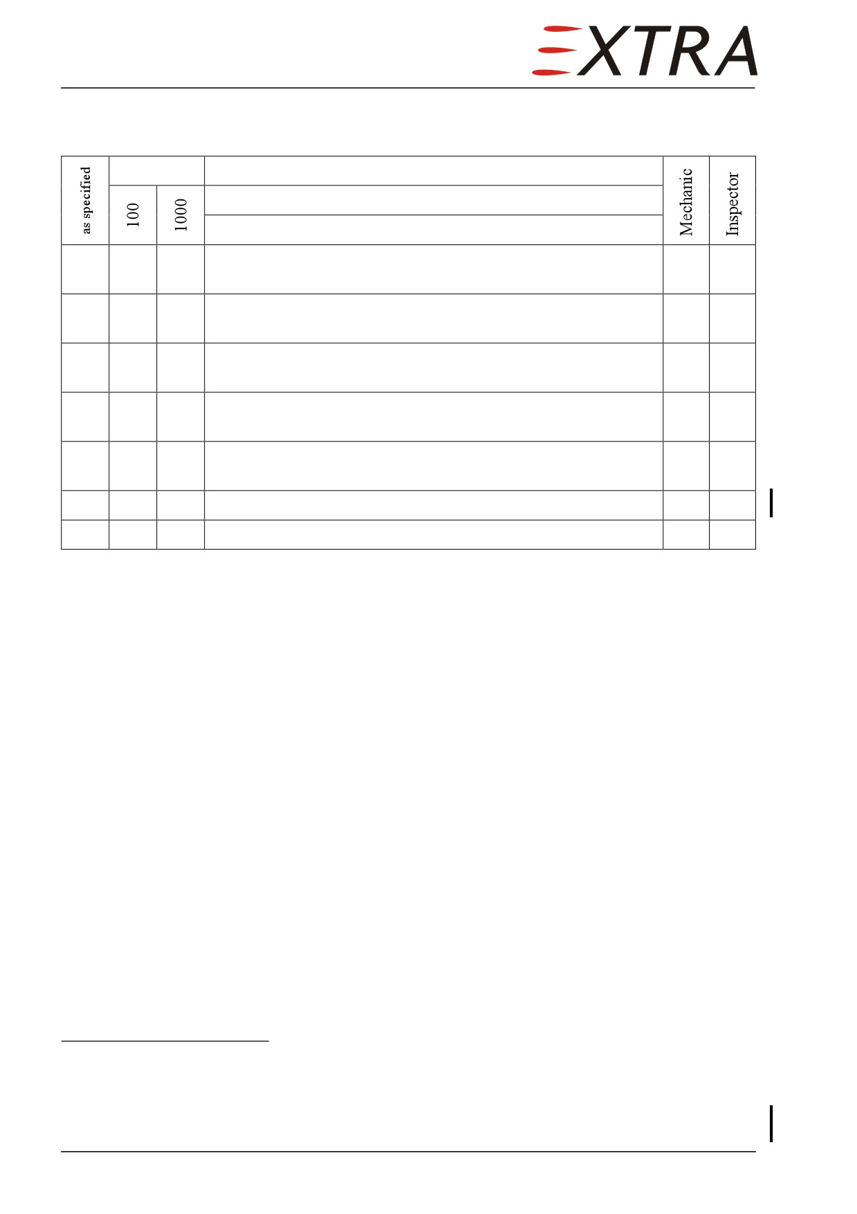
Fuel System
Flight Hours
Date:
Serial No.:
Description:
Inspect lines, hoses and clamps for leaks, improper condition
X
X
and looseness.
Inspect fuel pumps for leaks, poor general condition, and
X
X
insecure attachment.
Inspect fuel collector block and check valves for leaks,
X
X
improper condition, insecurity and insecure attachment.
Inspect fuel filter for leaks, improper condition, insecurity and
X
X
insecure attachment.
Check function of red fuel filter bypass button (monitor
X
X
annunciator panel).
1
Check function of fuel selector valve as per Chapter 28-20-03.
2
Change fuel filter element and O-rings.
1 Together with engine fuel maintenance. Refer to latest Rolls Royce 250-B17F Series Operation
and Maintenance Manual (LOAP 1).
2 Together with engine fuel pump filter replacement. Refer to latest Rolls Royce 250-B17F Series
Operation and Maintenance Manual (LOAP 1).
Page 14 05
Page Date:
Time Limits and Maintenance Checks
Oil System
Flight Hours
Date:
Serial No.:
Description:
1
Change engine Oil. Refer to Rolls Royce 250-B17F Series
Operation and Maintenance Manual (LOAP 1), Ch. 72-00-00,
ENGINE-SERVICING, Lubrication System Servicing, Oil
Change.
X
X
Inspect oil tank for insecurity of attachment, leaks and cracks.
Inspect oil system lines, hoses, fittings and clamps for leaks,
X
X
chafing, improper condition and looseness.
Remove foreign objects from inlet duct and inspect oil cooler
X
X
and fins for leaks, deterioration, distortion, insecure attachment,
loose or missing fasteners and other evidence of failure.
Inspect oil tank vent valves for insecurity of attachment and
X
X
poor condition.
1 together witch engine lubrication system maintenance
Refer to Rolls Royce 250-B17F Series Operation and Maintenance Manual (LOAP 1)
Page Date:
05 Page 15
Time Limits and Maintenance Checks
Bleed Air System
Flight Hours
Date:
Serial No.:
Description:
Inspect bleed air lines, pneumatic hoses, tubing, fittings and
clamps for leaks, chafing, improper condition and looseness.
X
X
Use clean filtered compressed shop air with a pressure not
exceeding 10 PSI.
Inspect valves for insecurity of mounting, poor condition and
X
X
improper electrical connections.
Inspect ejectors for insecurity of mounting, leaks and poor
X
X
condition.
Inspect pressure switch for insecurity of mounting, poor
X
X
condition and improper electrical connections.
Inspect air flow sensor for insecurity of mounting and improper
X
X
electrical connection.
Inspect acoustical muffler for insecurity of mounting, leaks and
X
X
poor condition.
Perform temperature switch function test (Refer to Chapter 21-
X
60-01).
Page 16 05
Page Date:
Time Limits and Maintenance Checks
Air Inlet and Exhaust System
Flight Hours
Date:
Serial No.:
Description:
Inspect air inlet and inlet heat ducts for leaks, cracks and poor
X
X
condition.
Check mechanic and electric (annunciation) function of inlet
heat. Lubricate as per Chapter 12-20-04 Lubrication Chart.
X
X
Check function of engine internal solenoid valve (“click” when
switched).
Inspect the exhaust pipes for burned areas, cracks, leakage,
X
X
deterioration, loose and missing brackets, clamps and
hardware.
Inspect induction and exhaust components for worn or
X
damaged areas, loose clamps, cracks and leaks.
05 Page 17
Time Limits and Maintenance Checks
Engine and Accessories
Flight Hours
Date:
Serial No.:
Description:
Perform complete engine inspection according to the latest
edition of Rolls Royce 250-B17F Series Operation and
1
Maintenance Manual (LOAP 1), Ch. 72-00-00, ENGINE-
INSPECTION/CHECK, Inspections, Scheduled Inspection &
Special Inspections.
2
Complete overhaul of engine or parts
X
X
Inspect oil temperature sensor unit for leaks and insecurity.
Inspect all wiring, fluid lines, hoses and electrical connections
X
X
for improper routing, improper support and evidence of
deterioration.
Visually inspect accessory to engine attaching hardware for
X
X
insecurity. Visually inspect airframe to engine connections for
insecurity and corrosion.
Inspect all accessories for poor condition, insecurity of
X
X
mounting and improper operation. Refer to component
manufacturer's Maintenance Manual.
Inspect and test the starter generator. Remove starter generator.
Check brush length and condition. Clean brushes by clean
3
filtered compressed shop air. Refer to the applicable starter
generator manufacturer's instructions. Reinstall starter
generator and ventilation. Inspect ventilation hose and
attachment for leaks, chafing, looseness and poor condition.
Inspect and test the stand-by alternator. Check alternator
X
X
externally for security of mounting and wiring. Refer to the
applicable alternator manufacturer's instructions.
Inspect firewall mounted equipment for insecurity of mounting,
X
X
improper electrical connections and poor general condition.
1 refer to Rolls Royce 250-B17F Series Operation and Maintenance Manual (LOAP 1)
2 see prior footnote
3 every 300 flight hours
Page 18 05
Page Date:
Time Limits and Maintenance Checks
Propeller and Governors
Flight Hours
Date:
Serial No.:
Description:
Perform propeller check according to the latest edition of MT-
X
X
Propeller Operation and Installation Manual E-610 (LOAP 3),
Section 6.2.1, and Service Bulletin No 1 (LOAP 5).
Perform Propeller-Power Turbine Governor Functional
Feather Check according to the latest edition of Rolls Royce
1
250-B17F Series Operation and Maintenance Manual
(LOAP 1), Ch. 72-00-00, ENGINE-DESCRIPTION AND
OPERATION, Operating Procedures.
Perform Propeller Overspeed Governor Functional Check
according to the latest edition of Rolls Royce 250-B17F Series
2
Operation and Maintenance Manual (LOAP 1) Ch. 72-00-00,
ENGINE-DESCRIPTION AND OPERATION, Operating
Procedures.
1 together with engine maintenance. Refer to Rolls Royce
250-B17F Series Operation and
Maintenance Manual (LOAP 1).
2 see prior footnote
Page Date:
05 Page 19
Time Limits and Maintenance Checks
Cabin and Equipment
Flight Hours
Date:
Serial No.:
Description:
Remove inspection covers, door covering and panels (carpet
X
X
must be removed for access to inspection covers on the cabin
floor).
Inspect cabin and cockpit for uncleanliness and loose
X
X
equipment that might foul the controls.
Inspect door locking mechanism for bending, cracks, pulled or
X
X
sheared fasteners, and loose parts.
Check upper and lower door for proper rigging. Refer to
X
X
Chapter 52-10-05.
Inspect door handles for play with the locking mechanism
X
X
fixed. No play allowed.
Check that the gas spring (10, Figure 52-4) connected to the
X
X
upper door handle axle pushes the locking mechanism to the
extreme positions (with door open).
X
X
Inspect the door locking pins and bushings for wear.
X
X
Inspect door seals for folding and damage.
X
X
Inspect the door hinges for cracks and side play.
Check upper door holding gas spring for general condition.
X
X
Spring must hold the upper door completely open. Max. 15 mm
static compression of spring allowed.
Check cables supporting the lower door for general condition
X
X
and correct length (tread must be horizontal). Check cable
joints and bolt connections for general condition.
1
Check emergency exit for general condition.
Check emergency exit locking mechanism for free movement.
1
Inspect for corrosion.
Inspect emergency exit door seals for folding, cracks and other
1
damage.
Perform a teardown inspection of the central door operating
X
device. Refer to Chapter 52-10-03.
X
X
Lubricate doors as per Chapter 12-20-04 Lubrication Chart.
Inspect crew seats for improper horizontal and vertical
X
X
operation and insecure locking function.
1 every 5 years
Page 20 05
Page Date:
Time Limits and Maintenance Checks
Flight Hours
Date:
Serial No.:
Description:
Check crew seats for proper engagement of pins to seat track
X
X
with occupied crew seat at the lowest vertical position.
X
X
Inspect seats and upholstery for tears and poor condition.
X
X
Inspect seat belts for insecurity of attachment.
Inspect seat belts as per SCHROTH Abbreviated Component
X
X
Maintenance Manuals for Restraint Systems Models 1-08-()
(LOAP 32) and 5-02-() (LOAP 33)
X
X
Check operation of cabin and instrument lights.
Inspect instruments, lines, wiring and attachments for poor
X
X
condition.
Inspect electric gyro instruments for poor condition, insecure
mounting, marking and improper operation. Overhaul or
X
X
replace as required. (Refer to the components manufacturer's
instruction.)
Test pneumatic system pressure regulator setting and pressure
X
switch setting as per Chapter 30-10-01.
Inspect avionics for improper installation and insecure
X
X
mounting.
X
X
Check electric trim operation and rigging.
X
X
Check operation of rudder pedals.
Inspect control wheels, column and switches for poor
X
X
condition.
1
Remove seats and paneling. Inspect control cables, pulleys and
connections for poor condition and insecurity.
X
X
Check operation of strobe, landing, navigation lights.
X
X
Inspect pitot/static system for leakage and obstruction.
X
X
Inspect altimeter and ATC transponder for improper condition.
2
Check that altimeter complies with latest revision of 14 CFR
Chapter 1 Part 43 Appendix E.
3
Check that transponder complies with latest revision of 14 CFR
Chapter 1 Part 43 Appendix F.
1 every 300 flight hours
2 every two years
3 annually
Page Date:
05 Page 21
Time Limits and Maintenance Checks
Flight Hours
Date:
Serial No.:
Description:
1
Inspect compass and compass deviation card for improper
indication and compensation. Refer to Chapter 34-20-02.
Perform IFD Magnetometer Check procedure as per Chapter
1
31-60-01.
Inspect all knobs, switches and levers and their mounting for
X
X
insecurity of attachment and poor condition.
Inspect engine controls for improper installation and improper
X
X
operation.
Inspect flight controls for improper installation and improper
X
X
operation.
X
X
Check operation of cabin heat and defrost controls.
Inspect circuit breaker mounting and wiring for poor condition
2
and insecurity.
X
X
Inspect environmental system ducts for poor condition.
Perform Blead Air System Leak Test, Cabin Leak Test and
3
Dump Test as per Ch. 21-00-00.
Inspect electrical panel components for poor condition and
X
X
insecurity.
Inspect forward side of pressure cabin outflow and safety
X
X
valves for poor condition and insecurity. Remove and clean as
shown in Chapter 21.
Inspect filter on cabin control outflow valve for contamination.
X
X
Clean or replace as required (see Chapter 21).
Inspect air condition evaporators, drain valves and mounting
X
X
for poor condition and insecurity.
X
X
Drain air condition evaporators.
Inspect portable fire extinguisher for improper service and poor
X
X
condition. Check inspection date.
4
Change batteries of emergency torch.
X
X
Reinstall inspection covers, panels and carpet.
1
Reinstall seats and paneling.
1 annually
2 every 300 flight hours
3 every 300 flight hours
4 annually or after each use
Page 22 05
Page Date:
Time Limits and Maintenance Checks
Fuselage
Flight Hours
Date:
Serial No.:
Description:
X
X
Remove exterior access panels from fuselage.
Inspect structure and exterior surfaces for deterioration,
X
X
distortion, cracks, dents, other evidence of failure,
uncleanliness and defective or insecure attachment of fittings.
Inspect windshield and windows for deterioration, nicks,
X
X
scratches, cracks and crazing.
Inspect electric windshield de-ice system for poor condition,
X
X
insecurity and improper operation.
X
X
Inspect environmental system ducts for poor condition.
Inspect air condition compressor and mounting for poor
X
X
condition and insecurity. Check condition and tension of
compressor drive belt.
Inspect air condition hoses and clamps for poor condition,
X
X
chafing and leaks.
X
X
Inspect air condition system wiring for fraying.
Inspect electrical leads, lines, radio antenna leads and attaching
X
X
for chafing, deterioration, improper routing, wear, insecure
installation and obvious defects.
Inspect antennas and coaxial cables for poor condition, insecure
X
X
mounting and improper operation. Refer to Figure 23-01.
Inspect static pressure ports for poor condition, obstruction and
X
X
damages. Inspect static heat for poor condition and improper
operation.
Inspect static lines and attaching for improper routing,
X
X
deterioration, poor condition and leaks. Drain static lines as per
Chapter 34-00-00.
Inspect ELT, trim servo and attachment for poor condition and
X
X
insecurity.
Check ELT battery replacement date. Refer to ARTEX
X
X
Description, Operation, Installation and Maintenance Manual
for the ME406 ELT (LOAP 30).
2
Perform a Cabin Leak Test and Dump Test. Dust particles on
door seals may indicate leakage position. Refer to Chapter 21.
X
X
Reinstall access panels (except every 300 flight hours).
1 every 300 flight hours
2 every 300 flight hours
Page Date:9. August 2013
05 Page 23
Time Limits and Maintenance Checks
Wing Assembly
Flight Hours
Date:
Serial No.:
Description
X
X
Remove avionic bay access panels and wing center fairing.
1
Remove fuselage access panels and all fuel compartment
access panels.
X
X
Inspect wings for dents, cracks and delaminations.
X
X
Inspect wing ventilation holes for obstruction.
2
Inspect wing spar main bolts and fittings for poor general
condition, distortion, and insecurity of attachment.
Extract wing spar main bolts in sequence (refer to Chapter 57-
3
10-00). Inspect bolt shanks for cracks, wear, corrosion and
insecurity. Install each bolt before extracting the next one.
Inspect inside wing structure in the area of access panels for
X
X
deterioration, delamination, distortion and poor general
condition.
4
Drain wing fuel tanks.
Inspect the inside of the wing tanks and lines for leaks, poor
4
condition and evidence of fungus. If contamination with fungus
is detected, contact the manufacturer.
Inspect tank bonding for improper installation and poor
X
X
condition.
Inspect fuel transmitter and electrical connectors for
4
uncleanliness, poor condition and insecurity.
4
Clean motive flow filters.
Inspect motive flow pumps for insecurity of attachment and
X
X
poor condition. Inspect electrical connectors for uncleanliness,
poor condition and insecurity.
4
Inspect fuel transfer system lines for leaks and poor condition.
Inspect fuel filler caps and flapper and float valves for poor
X
X
condition.
1 every 300 flight hours
2 annually
3 every 5000 flight hours
4 every 300 flight hours
Page 24 05
Page Date:
Time Limits and Maintenance Checks
Flight Hours
Date:
Serial No.:
Description
Inspect external fuel tank vent system for poor condition and
X
X
insecurity.
1
Inspect vent system inside the fuel tank for poor condition and
insecurity.
Risk of damage to flaps or upper door.
CAUTION
Function test of flaps only with upper door closed.
Inspect landing flaps and attachment for dents, cracks, de-
X
X
laminations and improper operation.
X
X
Inspect flap ventilation holes for obstruction.
Inspect landing flaps gear drive, flap position transmitter and
X
X
FLAPS switch for damage and improper operation.
Check flap guidance, flap actuation system, flap limit switches
X
X
and flap asymmetry senders. Refer to Chapter 27-50-00.
Lubricate flap track mechanism as per Chapter 12-20-04
2
X
X
Lubrication Chart.
Inspect navigation lights, recognition lights, wingtip strobe
X
X
lights for broken lenses, insecurity, improper wiring and
operation.
Inspect electrical leads, radio antenna leads, pneumatic lines
X
X
and attachment for improper routing, deterioration and
incorrect installation.
Inspect pitot tubes for poor condition, obstruction and damages.
X
X
Inspect pitot heat for poor condition and improper operation.
Inspect pitot lines and attaching for improper routing,
X
X
deterioration, poor condition and leaks. Drain pitot lines.
Inspect stall warning system for poor condition and insecurity
of installation. Perform operational check including stall warn
X
X
heat (Refer to POH, Section 4, Normal Procedures (Amplified),
Preflight Inspection).
Inspect de-icer system (wing and control surfaces) for poor
X
X
condition and improper operation.
1 every 300 flight hours
2 as specified in Chapter 12-20-04 Lubrication Chart
Page Date:9. August 2013
05 Page 25
Time Limits and Maintenance Checks
Control Systems and Surfaces
Flight Hours
Date:
Serial No.:
Description
Remove outer wing access panel, fin access panel, tail fairing,
X
X
fin tip and central horizontal stabilizer access panel.
X
X
Inspect control and stabilizer ventilation holes for obstruction.
Inspect stabilizer surfaces for dents, cracks, nicks and
X
X
delaminations.
Inspect rudder for insecurity of attachment, free movement,
X
X
dents, cracks and delaminations.
Inspect rudder hinges, attachment and bearings, stops,
X
X
centering spring for cracks, excessive wear, insecurity and
improper operation.
Inspect elevator surface for dents, cracks, nicks and
X
X
delaminations.
Inspect elevator hinges, elevator trim tab hinges, attachment
X
X
and bearing for poor condition, cracks, excessive wear,
insecurity and improper operation.
1
Inspect horizontal stabilizer main bolts for poor general
condition, distortion and insecure attachment.
2
Perform Horizontal Stabilizer Main Bolts Inspection as per
Chapter 55-10-01.
X
X
Check elevator trim system for improper operation and rigging.
Inspect elevator balance weight for looseness and poor
X
X
condition.
Inspect aileron, rudder, elevator and elevator trim cable
systems including turnbuckles, sleeves, fair leads, pulleys,
X
X
cable retracting springs and push pull rods per FAA-AC1
43.13-1B for lack of safetying, damage and improper operation.
X
X
Check all cable tensions using a tensiometer.
X
Inspect rudder control torque tubes, bottom panel, shelf,
linkage, control cable, sprocket wheel and interconnection for
X
poor condition, distortion and insecurity. Inspect control cable
connections for poor condition, chafing, distortion and
insecurity.
1 Annually
2 Every 5000 flight hours
Page 26 05
Page Date:
Time Limits and Maintenance Checks
Flight Hours
Date:
Serial No.:
Description
1
Examine control springs for mechanical damage, corrosion, and
wear at the clevisses. Refer to Chapter 27-00-10.
Lubricate control system components as per Chapter 12-20-04
X
Lubrication Chart
X
X
Reinstall access panels.
1 Annually
05 Page 27
Time Limits and Maintenance Checks
Landing Gear
Flight Hours
Date:
Serial No.:
Description
Nose gear and main gear extends and retracts under high pressure.
DANGER
Operation of the landing gear can cause death or injuries in its working
area !
Before beginning any work in the landing gear working area, pull OFF
the electric circuit breaker located on the left side panel and marked
GEAR CTRL.
In case of intentional gear operation by switch or circuit breaker
handling make sure, that neither a person nor material is in the landing
gear working area.
NOTE
With the aircraft being airborne or jacked with retracted landing gear
and BATT switch OFF, the hot bus feeds an AUX circuit, which supplies
the directional valves with electrical power to keep the landing gear in
the up-position. The AUX circuit is protected by the GEAR
AUX 1 (left side panel) and GEAR AUX 2 (E-box, engine compartment)
circuit breakers.
However, the nose gear and main gear will slowly extend due to valve oil
leakage, if the hydraulic pump is not being activated temporarily to
maintain hydraulic pressure. If retracted landing gear position is in-
tended, turn BATT switch ON and push circuit breakers GEAR CTRL (left
side panel) to the ON position, while the LANDING GEAR switch (left
main panel) is in the UP position.
If the aircraft is jacked with landing gear retracted and external power
not connected, the battery will be discharged within approx. 2 days.
X
X
Place the airplane on jacks.
Inspect the main gear struts for poor condition, cracks,
X
X
bending, distortion and insecurity.
Inspect the main gear and nose gear shock absorber for oil-
X
X
leakage and scoring.
Check the main gear struts for maximum extension and
X
X
overcentering of the radius struts.
Inspect the main gear bolts, bearings for lack of safety and poor
X
X
condition, cracks, excessive wear and insecurity.
X
X
Inspect the web plate at the main landing gear frame for cracks.
X
X
Check the parallel strut and axle bar for vertical clearance.
X
X
Inspect all actuator brackets for cracks.
X
Inspect main gear struts attachments for poor condition and
X
insecurity.
Page 28 05
Page Date:
Time Limits and Maintenance Checks
Flight Hours
Date:
Serial No.:
Description
Inspect track rods and attaching for poor condition, distortion
X
X
and insecurity.
X
X
Inspect rear preloaded axle stop for poor condition.
Check the nitrogen inflation of the main gear-shock absorber
X
X
(57 bar/827 psi ).
X
X
Inspect all wiring for poor condition, chafing and insecurity.
Inspect nose gear struts, trunnion pins and attachments for poor
X
X
condition and insecurity.
Inspect the nose gear trunnion for poor condition, cracks and
X
X
distortion.
Check the nose gear strut for maximum extension and
X
X
overcenter of the radius strut.
Check the nitrogen inflation of the nose gear shock absorber
X
X
(15 bar/218 psi ).
Inspect the nose wheel steering arm and its thrust bearing for
X
X
poor condition and any damage.
Inspect the fixing nose of the steering arm guide block for poor
X
X
condition, cracks and bending.
Inspect the spring device assembly of the nose wheel steering
X
X
and its attaching for looseness and any damage.
Inspect the nose wheel steering cables for wear and any
X
X
damage.
X
X
Inspect shimmy damper and attaching for poor condition.
Inspect the gas springs of the nose gear strut and attaching for
1
poor condition and insecurity. Perform Test Procedure as per
Chapter 32-30-25.
X
X
Inspect all wiring for poor condition, chafing and insecurity.
2
Remove hydraulic sump. Clean filter and change hydraulic
fluid (see Chapter 32-30-11).
Inspect the hydraulic lines for leakage, poor condition, chafing,
X
X
bulges and insecurity. Replace hoses and fittings as required.
Inspect the power pack and the distributor block for leakage,
X
X
poor condition and insecurity.
1 every 300 flight hours
2 every 5 years.
Page Date:9. August 2013
05 Page 29
Time Limits and Maintenance Checks
Flight Hours
Date:
Serial No.:
Description
Check the hydraulic fluid level of the hydraulic power pack
X
X
(see Chapter 32-30-11) Refill as required.
Inspect the main and nose gear doors, door hinges and levers
X
X
for cracks, distortion, insecurity and freedom of movement.
Inspect the main and nose gear door actuation mechanism for
X
X
poor condition, deformation, excessive free play and excessive
wear.
Inspect the hydraulic actuators and attachment for poor
X
X
condition and insecurity.
X
X
Check the main gear-interlocking actuator for locking.
Remove the push-pull rods from the upper main gear doors.
X
X
Fasten the doors in the open position by means of tapes.
Nose gear and main gear extends and retracts under high pressure.
DANGER
Operation of the landing gear can cause death or injuries in its working
area !
In case of intentional gear operation by switch or circuit breaker
handling make sure, that neither a person nor material is located in the
landing gear working area.
Before beginning any work in the landing gear operating area, esp. any
adjustment after performing test procedures, pull OFF the electric
circuit breaker located on the left side panel and marked GEAR CTRL.
Lift the aircraft on jacks. Operate the landing gear
(see Ch. 32-00-00 Operation). Inspect the hydraulic hoses and
X
X
track rods for freedom of movement, chafing and distortion in
extended and retracted position.
Perform gear up procedure (refer to Ch. 32-00-00 Operation).
Inspect the main and nose gear door actuation mechanism for
X
X
incorrect adjustment in the closed position. In case of doors
closing with too much play or tension, adjust length of
respective push rods (refer to Ch. 32-10-20/32-20-20).
1
Perform test procedures in accordance with Ch. 32-00-00 and
32-30-25 Test Procedures.
Clean the position switches; inspect for poor operation,
X
X
insecure seat and incorrect adjustment.
Inspect position switch wiring and harness for poor condition,
X
X
chafing, any damage and insecurity.
X
X
Check the gear position lights on the panel for operation.
1 Annually
Page 30 05
Page Date:
Time Limits and Maintenance Checks
Flight Hours
Date:
Serial No.:
Description
X
X
Reinstall push-pull rods to the upper main gear doors.
Clean and lubricate landing gear according to Chapter 12-20-
X
X
04 Lubrication Chart.
Replace all NMB M81935/1-6 rod ends (i.e. piston rod ends of
X
the short main hydraulic cylinders as well as the track rod ends,
refer to Figure 32-8 in Chapter 32-30-00).
Page Date:9. August 2013
05 Page 31
Time Limits and Maintenance Checks
Wheels and Brakes
Flight Hours
Date:
Serial No.:
Description
NOTE
Refer to on-aircraft inspections presented in the latest edition of
Cleveland Technician’s Service Guide (LOAP 34) and Component
Maintenance Manual (LOAP 35) for wheel, tire and break inspections.
Nose gear and main gear extends and retracts under high pressure.
DANGER
Operation of the landing gear can cause death or injuries in its working
area!
Before beginning any work in the landing gear working area, pull OFF
the electric circuit breaker located on the left side panel and marked
GEAR CTRL.
In case of intentional gear operation by switch or circuit breaker
handling make sure, that neither a person nor material is in the landing
gear working area.
NOTE
With the aircraft being airborne or jacked with retracted landing gear
and BATT switch OFF, the hot bus feeds an AUX circuit, which supplies
the directional valves with electrical power to keep the landing gear in
the up-position. The AUX circuit is protected by the GEAR
AUX 1 (left side panel) and GEAR AUX 2 (E-box, engine compartment)
circuit breakers.
However, the nose gear and main gear will slowly extend due to valve oil
leakage, if the hydraulic pump is not being activated temporarily to
maintain hydraulic pressure. If retracted landing gear position is in-
tended, turn battery switch ON and push circuit breaker GEAR CTRL
(left side panel) to the ON position, while the LANDING GEAR switch (left
main panel) is in the UP position.
If the aircraft is jacked with landing gear retracted and external power
not connected, the battery will be discharged within approx. 2 days.
X
X
Place the airplane on jacks.
X
X
Check the brake fluid level.
X
X
Inspect the brake assemblies for poor general condition.
X
X
Inspect the brakes and the master cylinder for leakage.
Inspect the brake lines and fittings for leakage and the hoses for
X
X
bulges. Replace hoses as required.
Inspect the brakes for corrosion, cracks and visible damage.
X
X
Inspect inlet fitting bosses and anchor bolt lugs for cracks.
X
Inspect fit of brake cylinder anchor bolts in torque plate
X
bushings for sloppiness. Excessive movement is cause for
removal and detailed inspection.
Page 32 05
Page Date:
Time Limits and Maintenance Checks
Flight Hours
Date:
Serial No.:
Description
Inspect the lining for wear (min. thickness 2.54 mm/0.1 inch.).
X
X
Replace if required.
X
X
Lubricate the brake guide pins using silicone - base lubricant.
Inspect the wheels for corrosion, cracks, loosen or broken bolts
X
X
and any damage.
X
X
Inspect the wheel nuts for improper installation and insecurity.
X
X
Check the wheel bearing clearance and wheels for free rotation.
Inspect the brake disc for rust, grooves, coning, cracks, wear
and visible damage. Check disc thickness (min. 8.25
X
X
mm/0.325inch.). Replace if required. (Refer to Cleveland
Technician’s Service Guide (LOAP 34) and Component
Maintenance Manual (LOAP 35).
X
X
Inspect the brakes for improper adjustment.
Remove the wheels and wheel bearings. Inspect wheel bearings
X
X
for excessive wear or damage. Replace on condition.
Inspect the snap rings for distortion and wear. Inspect grease
X
X
for contamination and solidification.
Repack the bearings with AEROSHELL 22C (per MIL-G-
X
X
81322).
Visually inspect the tires for wear, cuts, flat spots, and tread or
side wall damage. For tire changing refer to Cleveland
X
X
Technician’s Service Guide (LOAP 34) and Component
Maintenance Manual (LOAP 35).
X
X
Reinstall the wheels and secure.
Check tire inflation pressure. Main wheels 5.1 bar/74 psi, nose
X
X
wheel 3.5 bar/51 psi.
X
X
Inspect the wheels for improper alignment.
X
X
Lubricate as per Chapter 12-20-04 Lubrication Chart.
Depress ground safety switches by removing them from nose
1
gear torque link (See Figure 32-5). Check anti-retraction
system by gear lever operation. Reinstall switches.
Do not remove jacks before the landing gear is complete extended and
CAUTION
locked and the anti - retraction system has been checked.
Lower the aircraft as per Chapter 7 and remove the jacks and
X
X
jack points.
1 every 300 flight hours
Page Date:9. August 2013
05 Page 33
Time Limits and Maintenance Checks
Completion
Flight Hours
Date:
Serial No.:
Description
1
X
X
Perform Flight Test.
1
X
X
Perform checks given for special equipment installed.
Reinstall upper and lower cowling, panels and doors as
1
X
X
appropriate.
1
X
X
Aircraft conforms to specification of respective Authority.
1
X
X
All required Airworthiness Directives complied with.
1
X
X
All EXTRA mandatory Service Bulletins complied with.
All vendor Service Bulletins and Service Letters complied
1
X
X
with.
1
X
X
Check for proper Flight Manual.
1
X
X
Aircraft papers in order.
1 As required.
Page 34 05
Page Date:
Time Limits and Maintenance Checks
05-30-00
FLIGHTLINE INSPECTIONS
05-30-01
General
These checks include pre-flight and post-flight checks. When the aircraft is in
operation, these checks have to be performed daily.
05-30-02
Pre - Flight Check
This check must be carried out before the first flight of the day and serves as a
guideline for the pilot to check the general condition of the aircraft and the
engine.
The pre-flight check is fundamental for the flight safety and has to be
performed thoroughly in all details.
The schedule for the pre-flight check is in the EXTRA 500 Pilot's Operating
Handbook, Section 4.
05-30-03
Post - Flight Check
This post-flight inspection has to be performed after the last flight of the day
and consists of some visual checks.
The post-flight inspection should include all steps of the pre-flight check.
Additional measures:
1 Re-fuelling of the aircraft (refer to Chapter 12-10).
2 Reviewing of the entries in the log book for open discrepancies and correct
entries of the landings and the flight hours.
3 If necessary, mooring of the aircraft (refer to Chapter 10-20).
05 Page 35
Time Limits and Maintenance Checks
05-50-00
UNSCHEDULED MAINTENANCE CHECKS
05-50-01
General
Unscheduled checks are exceptional and have to be performed only after
abnormal events which are unusual at normal operating conditions and which
could possibly have caused damage to the aircraft or impaired the
airworthiness.
The 50 hours - Inspection for new, repaired or overhold engines is categorized
as an unscheduled check, since it has to be performed only once after the first
50 h of operation of the engine.
05-50-02
50 Hours - Inspection of Engine
If a new, repaired or overhauled engine is installed, perform a 50 hours -
inspection following the instructions of Rolls Royce
250-B17F Series
Operation and Maintenance Manual (LOAP 1).
05-50-03
Hard Landing
After an extremely hard landing or other unusual loads on the landing gear, a
thorough check of the respective components and their attachment points is
necessary. Even, when there are no obvious signs of damage, a visual check
has to be performed.
The check has to be carried out as follows:
1 The landing gear attachment area has to be examined for defects (e.g. cracks)
using a mirror and a torch, check the outer laminate for delamination (press
onto the laminate with your thumb).
Furthermore, the struts have to be checked for deformations and cracks.
IMPORTANT Examine wheel track
The tires have to be checked for cuts in the side wall and the brake discs for
impacts.
2 In the area of the nose gear, the belly of the fuselage should be checked for
cracks. Delaminations in the bonding area of the fire wall frame may also
occur.
The condition (cracks, deformations) of the complete nose gear has to be
checked.
Page 36 05
Page Date:
Time Limits and Maintenance Checks
3
After hard landings with damage observed, the attachment bolts of the landing
gear have to be examined for cracks (magnaflux or x-ray; dye-check is not
suitable in this case) or must be replaced.
4
In addition to the landing gear, all control surfaces (hinges, mass balance) and
the complete engine mount (engine truss, attachment points of the engine truss
at the fire-wall, shock mounts) have to be checked.
5
In addition, the wing structure has to be checked the main spar area plus the
shear force fittings and particularly the spar connection.
Also the wing-to-fuselage connection bolts have to be examined.
6
The same inspection has to be performed on the elevator.
IMPORTANT
If there are indications that structural parts are damaged, the
manufacturer has to be consulted for possible and suitable repair
methods.
7
If any damage of landing gear or aircraft structure is detected, perform an
engine special inspection. Refer to the applicable chapter of Rolls Royce 250-
B17F Series Operation and Maintenance Manual (LOAP 1).
05-50-04
Engine Fire
After an engine fire, all hoses and cables have to be checked and if necessary
replaced. A check of the engine has to be carried out according to the
procedures in the applicable chapter Rolls Royce 250-B17F Series Operation
and Maintenance Manual (LOAP 1).
If parts of the airframe or the engine cowlings are suspected of being damaged
by high temperatures (sign of blister on the protective paint, signs of resin
brown coloration or delamination), the manufacturer has to be consulted for
assistance in damage evaluation before the aircraft is returned into service.
05-50-05
Propeller Strike, Sudden Stoppage
and Violent Engine Stoppage
Refer to applicable Maintenance Instructions of MT-Propeller (LOAP 3-5) and
Rolls Royce (LOAP 1).
05-50-06
Lightning Strike
Contact the manufacturer.
Page Date:9. August 2013
05 Page 37