Extra 500. Maintenance Manual (2012) - page 1
Log of Revision
Issue
Date
Sign of approval
Date
1st Edition
31. March 2011
EASA Major Change
17. June 2011
(Chapter 4 & 5 only)
Approval N° 10035367
2nd Edition
The technical content of this
(Complete Manual
document is approved
except Chapter 4)
under the authority of
DOA N° EASA.21J.073
1st Revision, 2nd Edition
11. July 2012
The technical content of this
31. July 2012
document is approved
under the authority of
DOA N° EASA.21J.073
2nd Revision, 2nd Edition
The technical content of this
document is approved
under the authority of
DOA N° EASA.21J.073
Page Date:
Page A
List of Effective Page
A thru H
23-8 thru 12
11. July
2012
01-1 thru 8
24-1 thru 18
30. March
2012
02-1 thru 8
25-1 thru 16
30. March
2012
03-1 thru 4
27-1 thru 28
30. March
2012
04
see LoEP Chapter 04
28-1 thru 2
30. March
2012
05-1 thru 8
30. March
2012
28-3
9. August
2013
05-9
9. August
2013
28-4 thru 19
30. March
2012
05-10
30. March
2012
28-20 thru 22
9. August
2013
05-11 thru 16
9. August
2013
28-23 thru 28
30. March
2012
05-17
30. March
2012
29-1 thru 4
30. March
2012
05-18 thru 26
9. August
2013
30-1
30. March
2012
05-27
30. March
2012
30-2 thru 3
9. August
2013
05-28 thru 33
9. August
2013
30-4 thru 9
30. March
2012
05-34 thru 36
30. March
2012
30-10 thru 24
9. August
2013
05-37
9. August
2013
31-1
30. March
2012
05-38
30. March
2012
31-2
9. August
2013
06-1 thru 4
30. March
2012
31-3 thru 6
30. March
2012
07-1 thru 4
30. March
2012
31-7 thru 8
11. July
2012
08-1 thru 4
30. March
2012
31-9 thru 12
9. August
2013
09-1 thru 6
30. March
2012
32-1 thru 32
30. March
2012
10-1 thru 8
30. March
2012
32-33 thru 34
9. August
2013
11-1 thru 4
30. March
2012
32-35 thru 60
30. March
2012
12-1
30. March
2012
33-1 thru 10
30. March
2012
12-2
9. August
2013
34-1
30. March
2012
12-3
30. March
2012
34-2
9. August
2013
12-4 thru 18
9. August
2013
34-3 thru 4
30. March
2012
20-1 thru 12
30. March
2012
34-5
9. August
2013
21-1
30. March
2012
34-6
30. March
2012
21-2 thru 3
9. August
2013
34-7
9. August
2013
21-4 thru 5
30. March
2012
34-8 thru 12
30. March
2012
21-6 thru 30
9. August
2013
34-13
9. August
2013
22-1 thru 32
30. March
2012
34-14 thru 18
30. March
2012
23-1
30. March
2012
51-1 thru 5
30. March
2012
23-2
11. July
2012
51-6 thru 8
11. July
2012
23-3 thru 7
30. March
2012
51-9
9. August
2013
Page B
Page Date:
51-10
91-4
91-5
51-11
91-6
11. July 2012
51-12 thru 14
91-7 thru 8
51-15 thru 16
91-9
11. July 2012
51-17 thru 20
91-10 thru 11
51-21 thru 38
91-12
11. July 2012
52-1
91-13
91-14
11. July 2012
52-2 thru 18
91-15 thru 17
55-1
91-18
11. July 2012
55-2
91-19 thru 20
55-3 thru 5
91-21
11. July 2012
55-6 thru 20
91-22 thru 27
56-1
91-28
11. July 2012
91-29
56-2 thru 14
91-30
11. July 2012
57-1
91-31 thru 34
57-2
91-35
11. July 2012
57-3 thru 11
91-36
57-12
91-37
11. July 2012
91-38
57-13 thru 14
91-39
11. July 2012
61-1 thru 2
91-40
61-3 thru 4
91-41
11. July 2012
61-5 thru 6
91-42
71-1 thru 12
91-43
11. July 2012
73-1 thru 4
91-44 thru 45
91-46
11. July 2012
74-1 thru 4
91-47 thru 48
76-1 thru 12
91-49
11. July 2012
77-1 thru 10
91-50 thru 52
78-1 thru 2
91-53 thru 55
11. July 2012
78-3
91-56
91-57
11. July 2012
78- 4
91-58 thru 60
79-1
91-61
11. July 2012
79-2 thru 3
91-62 thru 65
79-4 thru 5
91-66
11. July 2012
79-6 thru 12
91-67 thru 71
80-1 thru 4
91-72
11. July 2012
91-73
91-1
91-74
11. July 2012
91-2 thru 3
11. July 2012
Page Date:
Page C
91-75 thru 82
91-83
11. July 2012
91-84
91-85 thru 87
11. July 2012
91-88
91-89
11. July 2012
91-90
91-91
11. July 2012
91-92
91-93
11. July 2012
91-94 thru 95
91-96
11. July 2012
91-97 thru 98
Page D
Page Date:
CONTENTS
Title
Page
Log of Revisions
..................................................................................................................... A
List of Effective Pages
........................................................................................................ B-C
List of Service Bulletins
......................................................................................................... D
Group/Chapter Title
Chapter
GENERAL
Introduction
........................................................................................................................... 01
How to Use the Service Manual
............................................................................................ 02
AIRCRAFT
General Description
............................................................................................................... 03
Airworthiness Limitations
..................................................................................................... 04
Time Limits/Maintenance Checks
......................................................................................... 05
Dimensions and Areas
........................................................................................................... 06
Lifting and Shoring
................................................................................................................ 07
Leveling and Weighing
......................................................................................................... 08
Towing and Taxiing
............................................................................................................... 09
Parking, Mooring, Storage and Return to Service
................................................................. 10
Placards and Markings
11
Servicing
................................................................................................................................ 12
Standard Practices - Airframe
................................................................................................ 20
AIRFRAME SYSTEMS
Air Conditioning
21
Auto Flight
22
Communications
23
Electrical Power
..................................................................................................................... 24
Equipment/Furnishings
.......................................................................................................... 25
Flight Controls
....................................................................................................................... 27
Page Date:
Page G
Group/Chapter Title
Chapter
Fuel
........................................................................................................................................ 28
Hydraulic Power
29
Ice and Rain Protection
30
Indication/Recording Systems
............................................................................................... 31
Landing Gear
......................................................................................................................... 32
Lights
..................................................................................................................................... 33
Navigation
............................................................................................................................. 34
STRUCTURES
Standard Practices and Structures - General
......................................................................... 51
Doors
52
Stabilizers
55
Windows
56
Wings
57
PROPELLER
Propeller
................................................................................................................................ 61
POWER PLANT
Power Plant
71
Engine Fuel and Control
73
Ignition
74
Engine Controls
76
Engine Indicating
77
Exhaust
78
Oil
79
Starting
80
MISCELLANEOUS
Charts
..................................................................................................................................... 91
Page H
Page Date:
Table of Contents
01-00-00
GENERAL
3
Address
............................................................................................................... 3
Contact
................................................................................................................ 3
01-00-01
Documents
......................................................................................................... 3
Aircraft:
3
Equipment:.......................................................................................................... 3
01-00-02
Special Tools
...................................................................................................... 4
Figure 01-1
Main Gear Bolt Extracting Tool
......................................................................... 4
Figure 01-2
Flap Track Snap Gauge
...................................................................................... 5
Figure 01-3
Front Wing Main Bolt Extracting Tool
.............................................................. 6
Figure 01-4
Rear Wing Main Bolt Extracting Tool
................................................................ 6
01-00-03
Trade Marks
7
01-00-04
Safety.................................................................................................................. 7
Page 2 01
01-00-00
GENERAL
According to the regulations of the FAR/JAR part
23, this Maintenance
Manual provides educated maintenance staff with information necessary for
servicing, maintaining and repairing the EXTRA 500. This Manual contains a
detailed description of systems including time limits for the particular
components, troubleshooting and instructions for the performance of inspection
and maintenance work. The instructions that are necessary for disassembly,
check, repair, maintenance or overhaul of vendor equipment are not
incorporated in this manual.
Address
EXTRA Flugzeugproduktions- und Vertriebs- GmbH
Schwarze Heide 21
46569 Hünxe
Germany
Contact
Email: extraaircraft@extraaircraft.com
Phone:
+49 2858-9137-0
Fax:
+49 2858-9137-30
01-00-01
Documents
Use the following documents in connection with this Maintenance Manual:
Aircraft:
1
EXTRA 500 Pilot’s Operating Handbook and Airplane Flight Manual, Doc.
No.: EA-0B701 most current revision
2
Service Bulletins
3
Aircraft Record
4
Airplane Log Book and Engine Log Book
Note
Check the Airplane Log Book documents are up-to-date and in
accordance with current applicable aviation authority regulations.
Since the regulations may require different documents and data, owner of
exported airplanes should check with their own aviation officials to
determine their individual requirements.
Equipment:
Applicable Instructions of Continuous Airworthiness for equipment installed.
Refer to the List of Applicable Publications (LOAP), Doc. No.: EA-0B710.00
most current revision, provided by EXTRA.
01 Page 3
01-00-02
Special Tools
Generally, for maintenance tasks no special tools are necessary. However,
there are a few exceptions as listed below. These items are available at
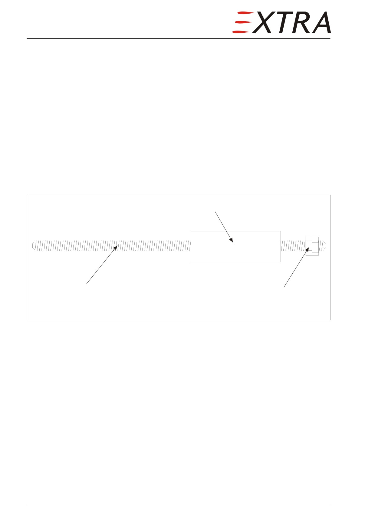
EXTRA. Alternatively, they can be crafted per instruction of Figures 01-1
through 01-4, using standard shop practices.
Description
Extra Part No.
Subject
Chapter
Main gear bolt
n/a
Main gear strut
32-10-10
extracting tool
removal
Flap track snap gauge EA - 15182W10
Flap guidance check
27-50
Front wing main bolt EA - 15001.1W
Wing removal
57-10
extracting tool
Rear wing main bolt EA - 15001.2W
Wing removal
57-10
extracting tool
Stroke bushing
Threaded rod M 10
Nut and counter nut
Figure 01-1
Main Gear Bolt Extracting Tool
Page 4 01
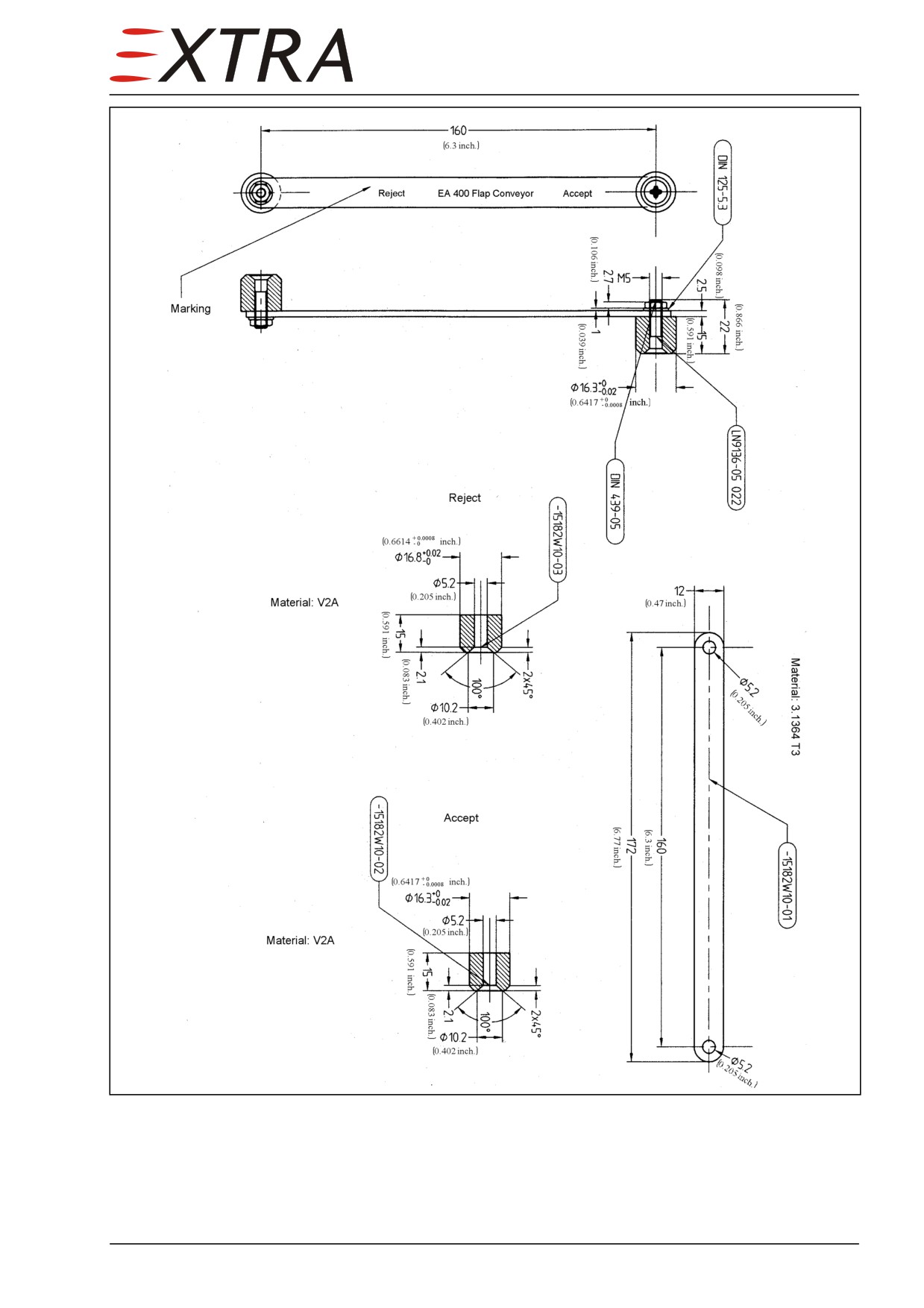
Figure 01-2
Flap Track Snap Gauge
01 Page 5
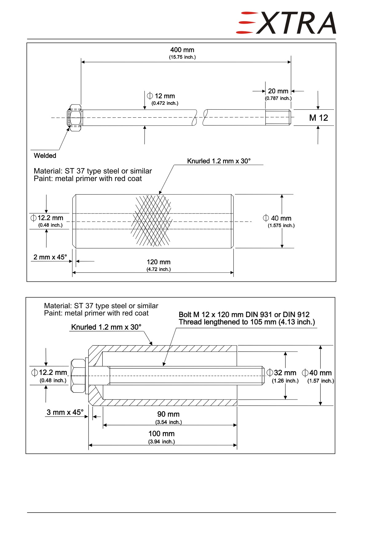
Figure 01-3
Front Wing Main Bolt Extracting Tool
Figure 01-4
Rear Wing Main Bolt Extracting Tool
Page 6 01
01-00-03
Trade Marks
Even when the ware or brand names used in this manual are not marked as
registered trade-marks, this does not mean, that these names are free in the
sense of trademark legislation.
01-00-04
Safety
To keep the security risks during the execution of the inspection and
maintenance work as low as possible, observe the following points:
1 Inspection and maintenance work has to be carried out only by qualified and
authorized personnel.
2 The execution has to be in accordance with the respective national safety
requirements.
3 Before beginning any work, this service manual has to be read and understood.
In case of doubt or lack of information the manufacturer has to be contacted for
advice.
4 The safety notes given in this manual are to be observed unconditionally.
Refer to Chapter 02 for information concerning safety notes.
01 Page 7
Chapter 02
How to Use the Maintenance Manual
02 Page 1
Table of Contents
02-00-00
GENERAL
3
02-10-00
MANUAL DESCRIPTION
4
02-10-01
Manual Set-Up
4
02-10-02
Chapter Set-Up
4
02-10-03
Page Numbering
4
02-10-04
Figure Numbering
4
02-10-05
Layout
5
02-10-06
Notes/Safety Notes
5
02-20-00
HANDLING
6
02-20-01
Revisions
6
02-20-02
Service Bulletin
6
02-20-03
Checklists
7
Page 2 02
02-00-00
GENERAL
The set-up of the manual, the chapters and the handling correspond to the
regulations of the Air Transport Association of America, ATA Specification
No. 100. However, the numbering of the pages and the layout have been
changed to make working with this manual easier.
02 Page 3
02-10-00
MANUAL DESCRIPTION
02-10-01
Manual Set-Up
The manual consists of groups, which are subdivided in chapters. Additionally
there are preceding pages, which contain the List of Effective Pages, the Lists
of Service Bulletins and the Record of Revisions. In the list of chapters the
groups are marked by capital characters.
02-10-02
Chapter Set-Up
The chapter numbering system used in this manual represents the chapter set-
up. It is a conventional dash-number breakdown. The number is composed of
three elements which consist of two digits each:
02-10-02
chapter - section - subject
The first element shows the chapter (here: "How to Use the Service Manual").
The second element shows the first subdivision, which is called "section"
(here: "MANUAL DESCRIPTION"). The third element shows the "subject",
which is handled within the respective section (here: "Chapter Set-Up"). The
first three digits refer to the definitions of the ATA Specification 100, where
they exist; the other digits are defined by the manufacturer. If a more detailed
breakdown is necessary, bold faced headlines like the following are used:
Powerplant
When headlines are referenced in the text they are presented in italic letters.
E.g.: see Powerplant paragraph.
02-10-03
Page Numbering
The page numbering begins at the coversheet of each chapter with "Page 1". In
contrast to the ATA Specification 100, the particular sections and subjects
don't start with a new numbering.
02-10-04
Figure Numbering
The figures are numbered in such a way that the first figure in each chapter
starts at "Figure XX-1".
Page 4 02
02-10-05
Layout
Apart from the headers and footers the layout consists of two columns. The
right column contains text, titles, tables, schedules and figures (figures also can
fill the whole page); the left column contains the chapter numbering, boxed
textmarkers for notes and safety notes as well as explanations.
02-10-06
Notes/Safety Notes
Safety notes in this manual are marked by a boxed textmarker in the margin
column and written in semi-bold characters. This manual distinguishes three
warning levels:
Represents any threatening danger for the personnel. The non-observation
DANGER of this safety note will result in death or serious injuries.
Represents a possibly dangerous situation for the personnel. The non-
WARNING observation of this safety note may result in injuries.
Represents a danger to equipment. The non-observation of this safety note
CAUTION results in destruction of equipment. This safety note does not exclude a
possible danger for the personnel.
Additional information given in this manual are also marked by boxed
textmarkers in the left column and are written in semi-bold characters:
IMPORTANT Represents an important hint. Often used when the non-observation could
endanger pilot or passengers during flight.
NOTE
Represents a useful or remarkable hint.
02 Page 5
02-20-00
HANDLING
02-20-01
Revisions
Maintenance Manuals and other technical publications in current revision
status are available over the World Wide Web direct link:
Cross-check your documents against these publications and replace pages as
necessary. Paper copies of publications will continue to be available if this is
your preferred format of publications. Orders can be placed by contacting
EXTRA.
NOTE
Pages of this Manual may not be exchanged and no alterations of or
additions to the approved contents may be made without the EXTRA
approval.
If revision of pages will be necessary, observe the following steps:
NOTE
Change revised pages immediately upon receipt.
1
Take out the old pages and destroy them.
2
Insert the new pages following the chapter and page numbers.
3
Replace the old pages "List of Effective Pages".
4
Enter the date on page "Record of Revision" and on page "2 = Record of
Revision" of Ch 04 if necessary.
Each revised page is marked at the bottom by the date of revision; revised parts
of the new page are marked by a bar on the left margin.
02-20-02
Service Bulletin
The Service Bulletins describe which procedures and how and when they are to
be carried out. Enter the receipt of each Service Bulletin in the Service Bulletin
List.
NOTE
The owner is responsible for incorporating Service Bulletins to the above
mentioned Service Bulletins List.
Page 6 02
02-20-03
Checklists
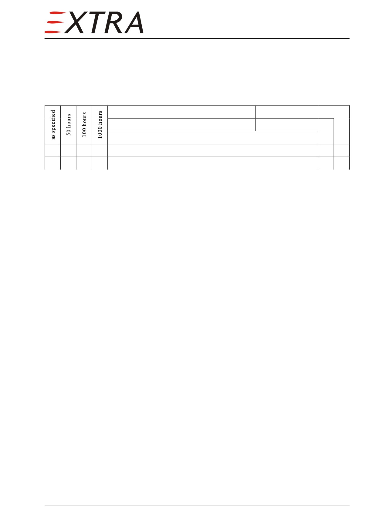
Observe the following steps when working with checklists:
1
Copy the respective check list for performing a check.
2
Enter the date at the top of the table.
Date:
Inspector
Serial No.:
Mechanic
Description
X
X
X
Text
X1
Text
3
Select the items to be worked out. The "X" at the beginning of the line is
written in the column which indicates the point of time when an item has to be
worked out. Specification for the first column is given by footnotes.
4
Work out the particular items and sign after execution (responsible mechanic
and inspector) using the respective boxes behind the item.
5
After completion of the inspection check file the list with entries in the Aircraft
Records.
6
Certify the completion of the check in the Aircraft Log Book.
02 Page 7
Chapter 03
General Description
03 Page 1
Table of Contents
03-00-00
GENERAL
3
Page 2 03
03-00-00
GENERAL
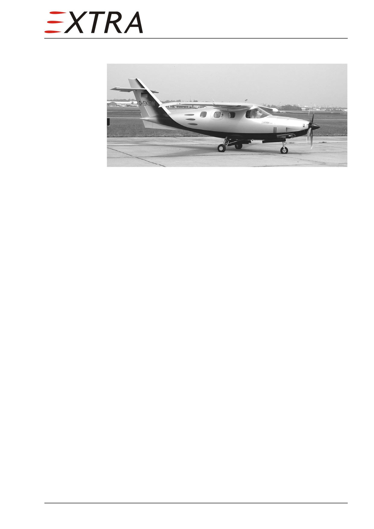
The EXTRA 500 is designed as a six-place, single engine, high-wing, full
composite airplane.
The fuselage consists of a skin with integrated longerons and frames.
The wing uses a double front spar and a rear spar interconnected by ribs.
The stabilizers use a front and a rear spar.
In general the skins of fuselage, wing, stabilizers and control surfaces consist
of carbon fiber facings and honeycomb. The supporting structures such as
longerons, frames, spars and ribs consist of carbon fiber with foam core.
Only the D-section of the wing consists of glass fiber with honey comb and
glass fiber ribs.
The EXTRA 500 has a hydraulically operated retractable tricycle landing gear
with a controllable nose wheel.
03 Page 3
Chapter 04
Airworthiness Limitations
Page Date: 31. March 2011
04 Page 1
Record of Revisions Chapter 04
Rev.
Date of
EASA Approval Date
Revised Pages
Description of Revision
No.
Revision
and Sign of Approval
LBA (NAA),
1st Ed.
4. June 2004
—
First edition
16. July 2004
N° 10035367
2nd Ed.
31. March 2011
—
Second edition
17. June 2011
FAA AEG IP M-1
2nd
Ed.
9. November
N° 10044853
2, 4 thru 5
Comments
Rev. 1
2012
10. May 2013
Proj. N° AT00413 CE-A
List of Effective Pages
04-1
31. March 2011
04-2
9. November 2012
04-3
31. March 2011
04-4 thru 5
9. November 2012
04-6
31. March 2011
Page 2 04
Page Date: 9. November 2012
Airworthiness Limitations
Table of Contents
04-00-00
GENERAL
4
04-00-01
Temperature Limit
4
04-00-02
Operating Time
4
04-10-00
LIFE LIMITED COMPONENTS
5
04-10-01
General
5
04-10-02
Replacement Time
5
04-10-03
Service Life Limited Components
5
Page Date: 31. March 2011
04 Page 3
04-00-00
GENERAL
IMPORTANT It is the operator's responsibility to make sure that time limits or life
limits for items in this chapter are not exceeded.
The airworthiness limitations items include mandatory replacement times
which may only be changed with permission of the applicable airworthiness
authority.
The Airworthiness Limitation section is FAA approved and specifies
maintenance required under paragraphs
43.16 and
91.403 of the Federal
Aviation Regulations, unless an alternative program has been FAA approved. *)
*) Legible statement pertaining to non US registered airplanes:
The Airworthiness Limitation section is approved by the regulatory authority
and specifies maintenance required under paragraphs 43.16 and 91.403 of the
Federal Aviation Regulations, unless an alternative program has been approved
by the regulatory authority.
04-00-01
Temperature Limit
The composite material used to manufacture the Extra EA 400-500 is qualified
for service temperatures up to 72° C (162° F) under load. As such, any surface
repainting or surface repair paint finish must be accomplished with white color
paint only.
04-00-02
Operating Time
Only the airframe and components as listed in Chapter 04-10-00 are subject to
a permissible operating time; concerning all other components recommended
replacement times are given in Chapter 05.
Page 4 04
Page Date: 9. November 2012
Airworthiness Limitations
04-10-00
LIFE LIMITED COMPONENTS
04-10-01
General
The replacement time of the life limited components listed in Chapter 04-10-02
must be accomplished not later than the specified period of operation for that
component or airworthiness directives.
04-10-02
Replacement Time
Items shown here must be replaced during the regular maintenance periods.
Item
Replace after
Fuselage
20,000 flight hours in service or
30,000 take-off and landing operations,
which ever comes first
Wing
20,000 flight hours in service
Wing Flap
20,000 flight hours in service
Aileron
20,000 flight hours in service
Vertical Stabilizer
20,000 flight hours in service
Rudder
20,000 flight hours in service
Horizontal Stabilizer
20,000 flight hours in service
Elevator
20,000 flight hours in service
04-10-03
Service Life Limited Components
The service lives of the EA 400-500 composite structure components as listed
in Section 04-10-02 have been demonstrated
up to 20,000 flight hours in service,
up to 30,000 take-off and landing operations (fuselage only).
Page Date:9. November 2012
04 Page 5
Chapter 05
Time Limits/Maintenance Checks
05 Page 1
Time Limits and Maintenance Checks
Table of Contents
05-00-00
GENERAL
5
05-00-01
Chapter Configuration
..................................................................................... 5
05-00-02
Words with Special Meanings
......................................................................... 6
05-10-00
TIME LIMITS
.................................................................................................. 7
05-10-01
General
7
05-10-02
Certification Authorities
.................................................................................. 7
05-10-03
Scheduled Maintenance Time Limits
7
05-10-04
Component Time Limits
.................................................................................. 8
Time Between Overhaul
..................................................................................... 8
Time Between Replacement
............................................................................... 8
Time Between Inspection
................................................................................... 9
05-20-00
SCHEDULED MAINTENANCE CHECKS
................................................ 10
05-20-01
General
10
05-20-02
Maintenance Checks Schedule
...................................................................... 10
05-20-03
Scheduled Maintenance Charts
..................................................................... 11
Operational Checks........................................................................................... 11
Miscellaneous
................................................................................................... 13
Fuel System
...................................................................................................... 14
Oil System
........................................................................................................ 15
Bleed Air System
.............................................................................................. 16
Air Inlet and Exhaust System
........................................................................... 17
Engine and Accessories
.................................................................................... 18
Propeller and Governors
................................................................................... 19
Cabin and Equipment
....................................................................................... 20
Fuselage
............................................................................................................ 23
Wing Assembly
................................................................................................ 24
Control Systems and Surfaces
.......................................................................... 26
Landing Gear
.................................................................................................... 28
Wheels and Brakes
........................................................................................... 32
Completion
....................................................................................................... 34
Page 2 05
Page Date:
Time Limits and Maintenance Checks
05-30-00
FLIGHTLINE INSPECTIONS
.....................................................................35
05-30-01
General
.............................................................................................................35
05-30-02
Pre - Flight Check
...........................................................................................35
05-30-03
Post - Flight Check
..........................................................................................35
05-50-00
UNSCHEDULED MAINTENANCE CHECKS...........................................36
05-50-01
General
.............................................................................................................36
05-50-02
50 Hours - Inspection of Engine
....................................................................36
05-50-03
Hard Landing
..................................................................................................36
05-50-04
Engine Fire
.......................................................................................................37
05-50-05
Propeller Strike, Sudden Stoppage and Violent Engine Stoppage
............37
05-50-06
Lightning Strike
37
05-50-07
Engine Overspeed............................................................................................38
05 Page 3
Time Limits and Maintenance Checks
05-00-00
GENERAL
This chapter is a guide. It will help you to perform the maintenance correctly.
You must perform the scheduled maintenance checks given in this chapter at
the recommended time. These checks are minimum requirements for keeping
the aircraft in a good technical condition.
The aircraft manufacturer can change the time between maintenance actions
and scheduled checks. If this happens, the aircraft manufacturer will supply the
data by Service Bulletins or Service Letters.
You can shorten the time between scheduled maintenance checks if the air-
craft operation makes it necessary. You must not extend the time between
scheduled maintenance checks without the aircraft manufacturer’s approval.
The aircraft manufacturer must give approval to any change to the aircraft or to
the maintenance checks schedule.
05-00-01
Chapter Configuration
Section 05-10-00 contains the time limits for maintenance actions and checks.
It also contains the time limits for components. Use the data in section 05-10-
00 to find out when to perform maintenance actions and checks.
Section 05-20-00 contains the scheduled maintenance checks to be performed
on different time intervals. It also contains data for the annual inspection if
required due to national regulations.
Section 05-30-00 contains data for flight line checks. Do a pre-flight check
before each flight. And do a post-flight check after each flight.
Section 05-40-00 is reserved.
Section
05-50-00 contains the unscheduled maintenance checks. Do these
checks after heavy landings, engine fire and propeller damage, or if the aircraft
has been operated outside the flight envelope.
05 Page 5
///////////////////////////////////////