Extra 500. Maintenance Manual (2012) - page 5
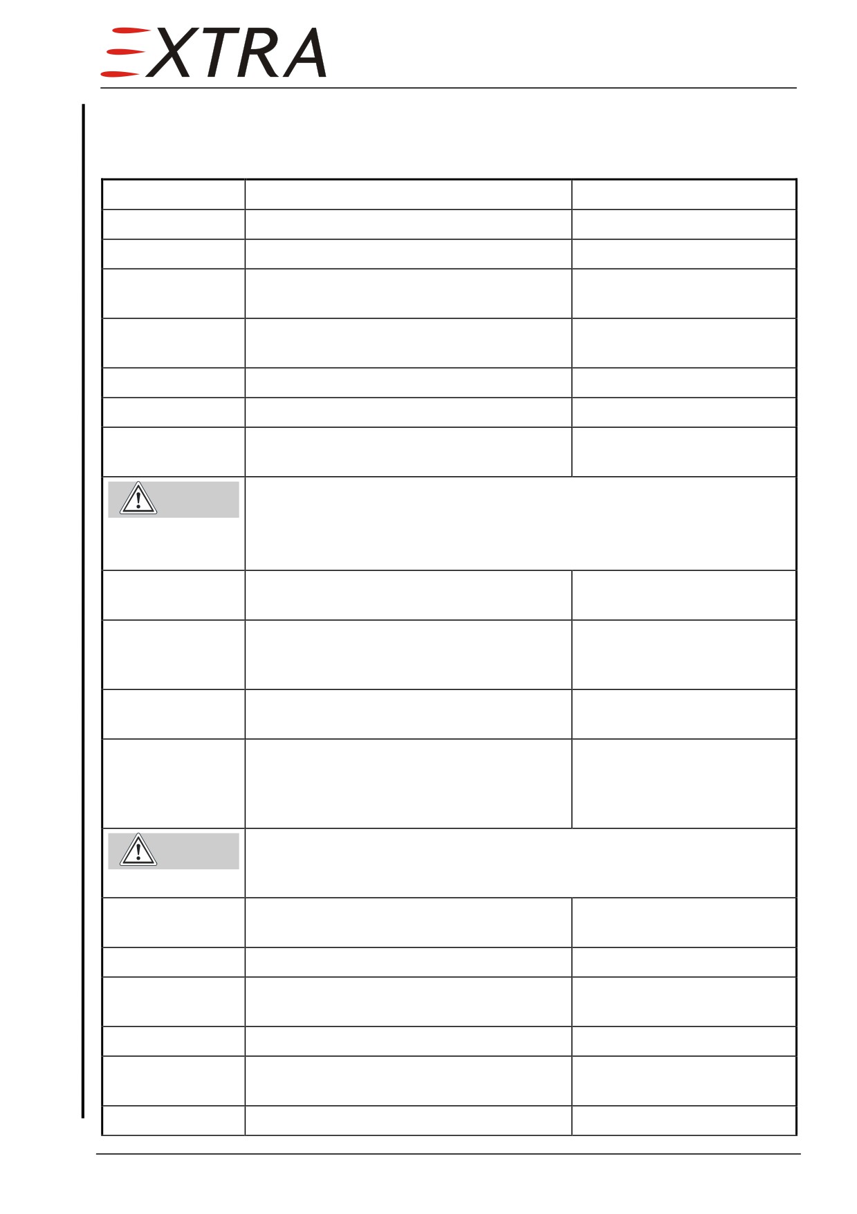
Cabin Leak Test
It is advisable to integrate the Dump Test in this test, because the necessary
preparations are very similar. Refer to Figure 21-1.
Detail Steps/Work Items
Key Items
1
Remove both upper engine cowlings.
Refer to Ch. 71-10-01/02.
2
Remove tail cone access panel.
Refer to Chapter 51-00-01
3
Plug the static reference port of the cabin
control outflow valve with tape.
4
Place an altimeter in the cabin, readable
from a window.
5
Set altimeter to 1013 mbar and note altitude.
6
Close the cabin door.
7
Remove inlet hose from the cabin inflow
box on the upper right firewall.
Risk of injury due to flying parts when pressurizing the cabin.
Warning
Follow cabin pressurization unit safety instructions before installing the
unit.
Apply Max. 5.5 psig air to the cabin.
8
Install a cabin pressurization unit or
equivalent to the cabin inflow box.
9
Let a helping person shut the cabin control
outflow valve by hand. Gently pull the valve
piston in its seat.
10
Pressurize cabin until altimeter reads
Tolerance +/− 500 ft
−3000 ft.
11
Switch off external pressurization unit,
engage stop watch and note altimeter
reading. Stop the time when altimeter
reaches the prior noted value.
Risk of injury when opening the door with cabin pressurized.
Door
Warning
could open with force.
Do not open the door until cabin has reached ambient pressure.
12
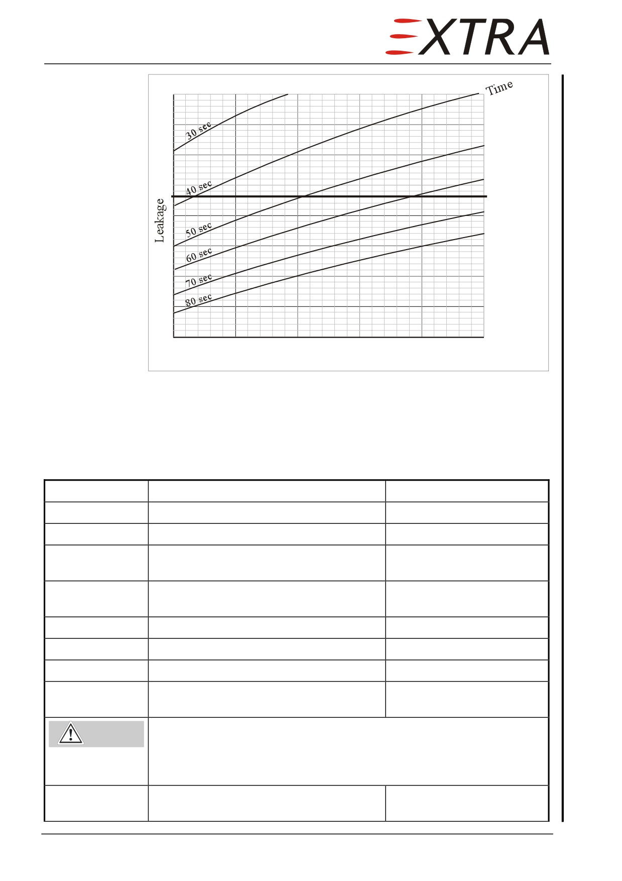
Calculate altitude difference and check if
Refer to Figure 21-2
time stopped is within limit.
13
Perform Dump Test if applicable.
14
Disconnect cabin pressurization unit from
cabin inflow box.
15
Re-install inlet hose to cabin inflow box.
16
Remove plug from static reference port of
the cabin control outflow valve.
17
Re-install access panels.
Refer to Chapter 51-00-01
Page Date:
21 Page 9
Upper Limit
1500
2000
2500
3000
3500
4000
Altitude Difference (ft)
Figure 21-2
Cabin Leakage Chart
Dump Test
It is advisable to combine this test with the Cabin Leak Test.
Refer to Figure 21-1.
Detail Steps/Work Items
Key Items
1
Remove both upper engine cowlings.
Refer to Ch. 71-10-01/02.
2
Remove tail cone access panel.
Refer to Chapter 51-00-01
3
Plug the static reference port of the cabin
control outflow valve with tape.
4
Let a helping person enter the cabin with an
additional altimeter.
5
Set altimeter to 1013 mbar and note altitude.
6
Switch BATT on.
7
Close the cabin door.
8
Remove inlet hose from the cabin inflow
box on the upper right firewall.
Risk of injury due to flying parts when pressurizing the cabin.
Warning
Follow cabin pressurization unit safety instructions before installing the
unit.
Apply Max. 5.5 psig air to the cabin.
9
Temporarily attach a cabin pressurization
unit or equivalent to the cabin inflow box.
Page 10 21
Page Date:
Detail Steps/Work Items
Key Items
10
Let a helping person shut the cabin control
outflow valve by hand. Gently pull the valve
piston in its seat.
11
Pressurize cabin until altimeter reads
Tolerance +/− 500 ft
−3000 ft.
12
Engage RH (outside) squat switch by hand.
Check if safety valve clicks and cabin
pressure drops.
13
Release squat switch.
14
Pressurize cabin again until altimeter reads
Tolerance +/− 500 ft
−3000 ft.
15
Position PRESS-switch to DUMP.
Check if safety valve clicks and cabin
pressure drops.
16
Switch off external pressurization unit.
17
Switch BATT off.
Risk of injury when opening the door with cabin pressurized.
Door
Warning
could open with force.
Do not open the door until cabin has reached ambient pressure.
18
Disconnect cabin pressurization unit from
cabin inflow box.
19
Re-install inlet hose to cabin inflow box.
20
Remove plug from static reference port of
the cabin control outflow valve.
21
Re-install access panels.
Page Date:
21 Page 11
21-00-01
Sceet Hoses
The worm drive hose clamps of the bleed air system are secured with a safety
wire.
Replacement
Detail Steps/Work Items
Key Items
1
Remove both upper engine cowlings.
Refer to Ch. 71-10-01/02.
2
Remove hose.
worm drive hose clamps,
(safety wire)
3
Cut new SCEET hose to length.
4
Slip the worm drive hose clamps over the
hose.
5
Slip both hose layers over the fittings.
6
Fasten worm drive hose clamps on both
Apply safety wire to all bleed
sides.
air hose clamps.
Page 12 21
Page Date:
21-10-00
COMPRESSION
Description
Refer to Figure 21-1.
The system consists of the engine compressor, bleed ports, a bleed air
manifold, a shut-off valve, a mass flow control valve, a mass flow controller, a
mass flow sensor, hoses, and the ENV AIR switch on the left side panel.
Engine bleed air is used for cabin pressurization. Bleed air is taken from the
engine compressor by means of two bleed ports. A forward-facing port is
located on the right top of the engine compressor scroll. On its left bottom
another downward-looking port is located. The bleed ports incorporate orifices
(sonic venturi) which are installed with special O-rings. Bleed air is then routed
through pressure hoses to the bleed air manifold located on the left engine side.
Just above the primary shut-off valve is installed, which allows switching on or
off cabin pressurization (and also heating) by means of the ENV AIR switch.
The mass flow control valve is installed above the shut-off valve. It takes bleed
air and/or ram air tapped from the left air-to-air cooler inlet to control the mass
flow. The valve is governed by a computerized mass flow controller installed
inside the cabin behind the side paneling between the cabin door and the pilot’s
seat. The controller receives mass flow data from the mass flow sensor
installed to a flange downstream the bleed air muffler.
21-10-01
Primary Shut-off Valve
Removal/Installation
The primary shut-off valve is screwed to the mass flow control valve. For this
reason it is advisable to firstly remove both valves together and to disconnect
them later by turning the shut-off valve.
Detail Steps/Work Items
Key Items
1
Remove LH engine cowling.
Refer to Chapter 71-10-01.
2
Disconnect bleed air manifold from shut-off
the valve.
3
Cut the electrical wiring from the shut-off
Reconnect later by splicing.
valve.
4
Disconnect the SCEET hoses from the mass
flow control valve.
5
Disconnect the electrical wiring from the
mass flow control valve.
6
Disconnect the mass flow control valve
4 bolts
from the engine mount and remove both
valves together.
Page Date:
21 Page 13
Detail Steps/Work Items
Key Items
7
Loosen counter nut between the two valves.
8
Unscrew the shut-off valve from the mass
Turn the complete shut-off
flow control valve.
valve. Watch the copper O-
ring.
9
Install in reverse sequence of removal.
21-10-02
Mass Flow Control Valve
Removal/Installation
Follow the procedure given in Section 21-10-01.
21-10-03
Mass Flow Sensor
The mass flow sensor is electrically connected to its control box located on the
nose gear firewall.
Removal/Installation
Detail Steps/Work Items
Key Items
1
Remove LH engine cowling.
Refer to Chapter 71-10-01.
2
Remove cable straps and tie tool wraps from
the electrical wiring between sensor and
control box.
2
Remove sensor.
4 bolts on muffler flange
3
Remove control box.
4 screws, 3 else connections
4
Install in reverse sequence of removal.
Check
Detail Steps/Work Items
Key Items
1
Remove LH engine cowling.
Refer to Chapter 71-10-01.
2
Remove sensor from muffler.
4 screws
3
Check 2 wires in sensor are intact.
Replace sensor if wires are
broken.
4
Install in reverse sequence of removal.
Page 14 21
Page Date:
21-10-04
Mass Flow Controller
Removal/Installation
Detail Steps/Work Items
Key Items
1
Remove left side armrest paneling.
Refer to Chapter 25-20-21.
2
Disconnect the electrical connector from the
mass flow controller.
2
Remove mass flow controller.
4 attachment nuts
5
Install in reverse sequence of removal.
21-10-05
Muffler
The muffler is directly mounted to a flange providing a holding fixture for the
mass flow sensor.
Removal/Installation
Detail Steps/Work Items
Key Items
1
Remove LH engine cowling.
Refer to Chapter 71-10-01.
2
Remove mass flow sensor.
Remove 4 screws.
3
Disconnect SCEET hoses from muffler and
flange.
4
Remove attachment bolts of hose clip and
hose clamp carrying muffler and flange.
5
Remove muffler with flange.
6
Install in reverse sequence of removal.
Page Date:
21 Page 15
21-20-00
DISTRIBUTION
Description
Refer to Figure 21-1.
The system consists of a valve box, SCEET hoses, a distribution valve, a
Bowden cable with a handle on the center console panel and the panel vent
fans.
Ram air or bleed air is ducted into the cabin (refer to Section 21-10 for the
bleed air system).
Ram air is taken from the oil cooler inlet on the right engine side and routed
through SCEET hoses to a valve box on the firewall. 2 check valves are
mounted to the valve box (ram air and bleed air side). Additionally the valve
box has a holding fixture for the duct temperature sensor. The cabin inflow
check valve is mounted between the valve box and the firewall.
Inside the cabin a valvular operated air distributor guides the air stream to the
windshield and/or legroom dispensers. The air distributor has also a holding
fixture for the temperature switch.
For better ventilation in the forward cabin section two vent fans are installed in
the LH and RH side of the instrument panel. Each vent fan sucks air from
behind the panel. On the discharge side each vent fan is connected to an
eyeball vent, which can be adjusted to direct or shut off the airflow. Two
switches, placed on the instrument panel near the resp. air outlet, control the
vent fans. The electric fan motors are protected by a 2 A - fuse.
The evaporators
(refer to Section
21-50) also work as cabin fans. Both
evaporator blowers work with different power settings in low or high mode.
21-20-01
Panel Vent Fans
Removal/Installation
Detail Steps/Work Items
Key Items
1 a (RH vent fan)
Remove RH IFD and right main panel.
Refer to Chapters
31-60-01
and 31-10-03
1 b (LH vent fan)
Remove LH and RH IFD and analogue
Refer to Chapter
31-60-01
engine indicator.
and Chapter 77-40-01
2
Loosen worm drive hose clamp on vent fan
casing.
3
Disconnect electrical wiring.
4
Remove vent fan with casing.
5
Disassemble vent fan and casing if
4 bolts
applicable.
6
Remove eyeball vent.
1 nut
Page 16 21
Page Date:

Detail Steps/Work Items
Key Items
7
Reverse procedure for installation.
8
Perform pitot/static test.
According to FAR 43,
Appendix E and AC 43.13-
1B CHG1 (or later) § 12-59
Page Date:
21 Page 17
21-30-00
PRESSURIZATION CONTROL
Description
Refer to Figure 21-1.
The system consists of the engine compressor, two sonic venturi
(flow
limiters), a cabin control outflow valve, an unregulated safety valve, the cabin
pressurization/dump switch, the cabin pressure controller, the landing gear
squat switch, and two indicators, one for cabin altitude and differential pressure
and one for cabin rate-of-climb.
Pressurized air is supplied from the engine bleed air through the sonic venturi
and then through a check valve into the cabin. Adequate flow to maintain
pressurization up to the maximum differential pressure of 5.5 PSI is provided
by the engine at normal power setting. Power changes should be made
smoothly to prevent sudden changes in pressurization air inflow resulting in
cabin pressure transients.
Operation
The airplane may be operated in either the pressurized or depressurized mode.
The mode selection is made with the cabin pressurization switch, which either
activates the cabin control outflow valve or leaves it open. Mode operation
should be selected prior to takeoff. If a change from pressurized to
depressurized mode must be made while airborne, depressurize the cabin
following the procedure given below before turning the dump switch as
otherwise a rapid decompression occurs, which would cause discomfort to the
passengers. When changing from unpressurized to pressurized mode, the cabin
altitude rate of change will be limited by the pressurization controller. The
valves are also opened by the landing gear squat switch assuring depressurized
mode when aircraft is on ground to avoid bursting the cabin door due to cabin
pressure when opening.
In the pressurized mode cabin pressure is regulated by the cabin control
outflow valve allowing air to exhaust either to the pressure level preselected by
the cabin pressure controller or to maximum differential pressure level. Setting
the center dial (identified as “Flight Level”) of the cabin pressure controller
will suggest the system being at a certain flight altitude. So the system will
maintain the corresponding cabin altitude (about 5.5 PSI above static pressure
of flight level) or reach it with the rate set by the rate control knob located on
the lower left corner of the pressurization controller. Only in case of maximum
differential pressure is reached or flight level is below the selected cabin
altitude, cabin altitude changes with the same rate the flight altitude does.
In case of failure of the cabin outflow control valve the safety valve will open
at a differential pressure of slightly above 5.5 PSI to avoid structure damage.
Handling
Use the cabin pressure controller as follows. Also refer to the sample chart
(Figure 21-1).
1
Activate the pressurization controller by turning on the cabin pressurization
switch. Make sure the ENV AIR switch is ON.
Page 18 21
Page Date:
2
Set the published official airport altitude (such as shown on flight charts) under
the index arrow by turning the center control knob.
3
Turn the index arrow of the rate control knob (lower left corner of the control)
to the 12 o’clock position (approx. 500 fpm).
These steps set the system to pressurize at approximately 700 feet above the
runway after takeoff. The system will hold this cabin altitude until the
maximum differential altitude is reached (see “Cabin Altitude with minimum
Flight Level Setting” line of Figure 21-1) or a different cabin pressure is
selected.
4
After having cleared the airport area and established the climb and being on
course to the destination (see “a” on 0), select the flight level corresponding to
the intended cruise altitude in the center dial and align that with the index
arrow. This alignment also indicates the approximate cabin altitude (within
approx. 700 feet) at the index on the larger numbers marked “Airport Alt.”.
5
Increase or decrease the rate at which the cabin changes altitude for the best
comfort level from normally
500 fpm by turning the rate knob counter
clockwise for decreasing or clockwise for increasing the rate.
Usually it is the best method to set the rate to reach the changed cabin pressure
(referenced from the “Airport Alt.”) slightly ahead of reaching the cruising
altitude (550 fpm in the sample of Figure 21-1). This selected altitude will be
maintained until the aircraft changes altitude sufficiently to reach the max.
differential pressure or descends sufficiently to go below the selected airport
altitude.
6
When the aircraft reaches the proximity of the destination and starts to descent
(see “b” on 0), set the selector knob to the published airport altitude.
7
Set the rate so that the selected airport altitude is reached in the cabin prior to
descending to that altitude (650 fpm in the sample of Figure 21-1).
When approaching the runway, the pressurization will cease approximately 700
feet above the landing prior to landing. Should any slight pressure remain, the
remainder will dump when the squat switch closes. However, this is an
additionally safety device, because landing with cabin pressurized is not
allowed.
If pressurization mode shall be terminated during flight, follow the
CAUTION
procedure above, setting the airport altitude equal to the momentary flight
altitude. Do not switch to the depressurized mode before the selected
airport altitude has been reached.
Page Date:
21 Page 19
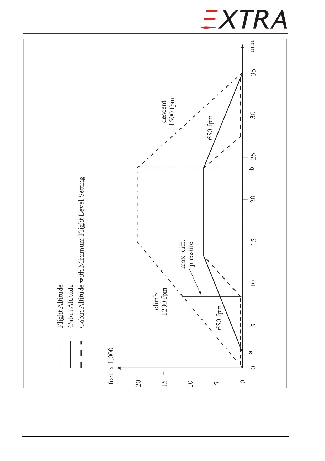
Figure 21-1
Cabin Pressurization Sample Chart
Page 20 21
Page Date:
21-30-01
Cabin Outflow Control Valve Filter
Replacement
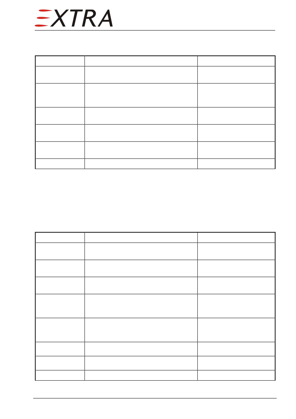
Detail Steps/Work Items
Key Items
1
Remove upper half of rear baggage
Machine screws AN 526
compartment wall.
10-32
2
Loosen the filter retention screw on the
It is not necessary to remove
control outflow valve housing until the filter
the screw entirely.
flange is free to rotate.
3
Rotate the filter until the flat on the filter
clears the screw head.
4
Remove the filter cartridge and replace with
new one.
5
Rotate the filter so filter flange is captured
by the screw head.
6
Tighten filter retaining screw.
21-30-02
Cabin Outflow Control Valve
The valve is attached to the LH side of the pressure dome.
Removal/Installation
Detail Steps/Work Items
Key Items
1
Ensure BATT switch is OFF and no external
power connected.
2
Remove upper half of rear baggage
Machine screws AN 526
compartment wall.
10-32
3
Remove tail cone access panel on LH
fuselage side.
4
Remove valve flange from pressure dome.
8 stop nuts MS 21044 AN3
with washers AN960 - 10L
(3/8 inch.)
5
Remove overflow tube.
9/16 fitting; retain with 11/16
wrench at pressure dome
fitting
6
Disconnect electrical connector.
7
Lift up valve from pressure dome
8
Install in reverse sequence of removal
Page Date:
21 Page 21
21-30-03
Safety Valve
The valve is attached to the RH side of the pressure dome.
Removal/Installation
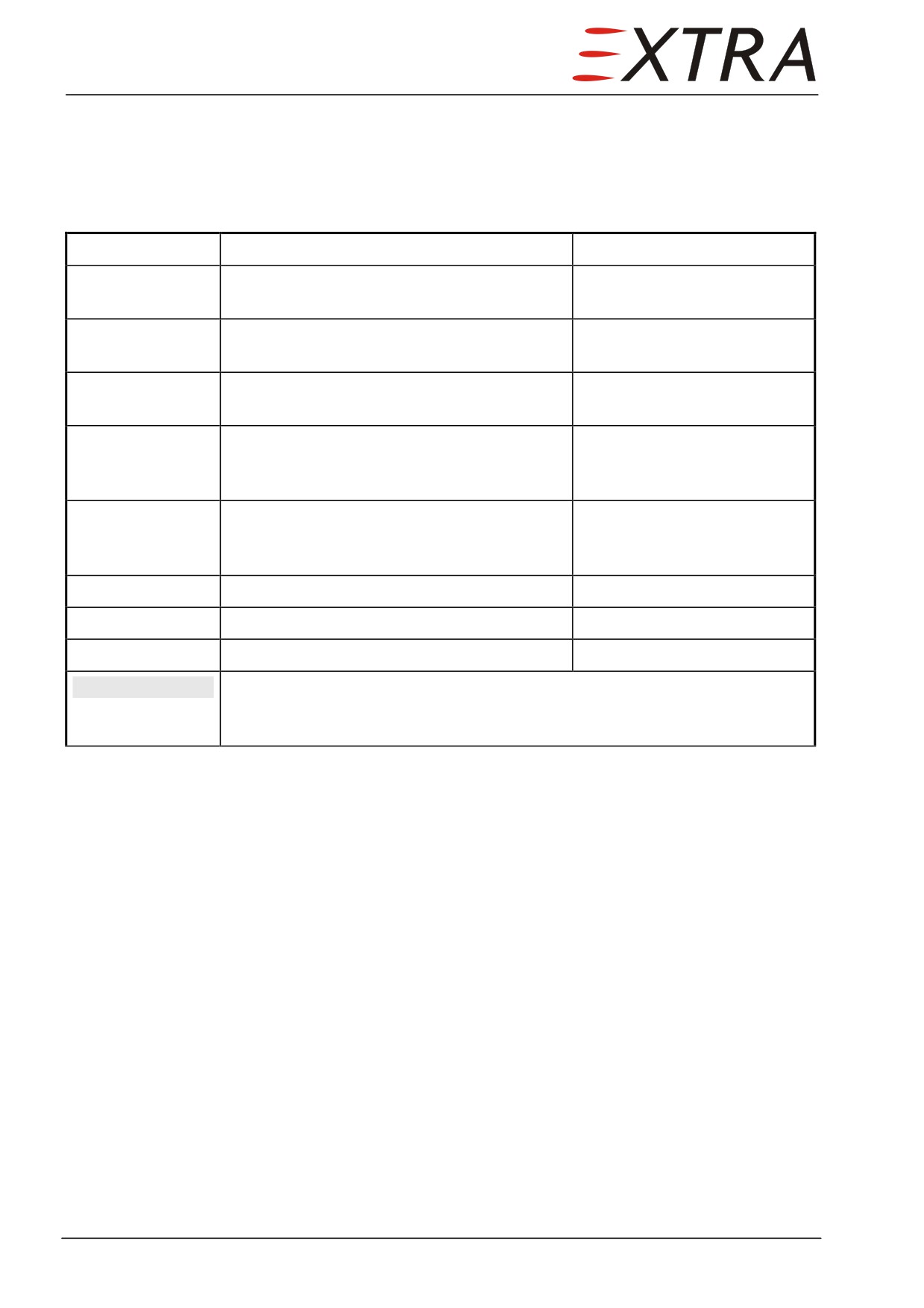
Detail Steps/Work Items
Key Items
1
Ensure BATT switch is OFF and no external
power connected.
2
Remove upper half of rear baggage
Machine screws AN 526
compartment wall.
10-32
3
Remove tail cone access panel on LH
fuselage side.
4
Remove valve flange from pressure dome.
8 stop nuts MS 21044 AN3
with washers AN960 - 10L
(3/8 inch.)
5
Remove overflow tube.
9/16 fitting; retain with 11/16
wrench at pressure dome
fitting
6
Remove electrical connector
7
Lift up valve from pressure dome
8
Install in reverse sequence of removal
Observe the following hint
NOTE
Verify that blind plug at vacuum port is installed correctly. With
installed valve, the vacuum port is accessible behind the rear baggage
compartment wall.
Page 22 21
Page Date:
21-50-00
COOLING
Description
Refer to Figure 21-1.
The aircraft is standard equipped with an electrically driven vapor cycle air
conditioning system. The system consists of a compressor condenser module,
two evaporators and the switches in the CABIN section of the left side panel.
The electrically driven compressor condenser module is installed in the
unpressurized part of the tail cone aft of the rear pressure dome. Cooling air for
the condenser (circulated by the condenser fan) is taken from an inlet in the left
fuselage side aft of the cabin door and dumped overboard through an outlet on
the same side.
The cabin recirculation air is cooled by means of two evaporators. The front
evaporator is installed behind the co-pilot seat and the aft evaporator in the aft
pressure dome area. Condensation at the evaporators is drained by means of a
float type check valve for each evaporator.
The air condition system is activated by the AIR CON switch located in the left
side panel. The air-condition will only operate effectively with the cabin
blower VENT switch at least in LOW position.
The electric air-condition provides the ability to operate the system on ground
using ground power without the necessity to run the aircraft engine.
NOTE
It is not possible to operate the air condition on battery power as the high
current draw would shortly lead to a depleted battery. Therefore for
operation either the aircrafts generator (engine running) or a sufficient
external power source (capacity min. 100 A at 28 VDC) has to be
connected to the aircraft bus system. 125 A is recommended for maximum
cooling capacity. When using external power the battery must be off.
Service and Maintenance
Servicing of the air-conditioning unit shall be performed by an approved air-
conditioning service station; only R-134a type refrigerant must be used.
The air-conditioning compressor condenser module is equipped with
conventional evacuating and charging connections.
After new system plumbing installation, component replacement or line or
hose rupture, a leak check is required, see Enviro Systems General Operating,
Servicing and Maintenance Manual for Airborne R-134a Air-conditioning
Systems (LOAP 13) for leak check and general charging procedures.
Refer to this Manual also for component maintenance procedures.
Access to the compressor condenser module is gained through the tailcone
access hatch. Both low and high pressure service ports are located at this unit.
Charging quantity of the installation is 0.650 kg +/- 0.050 kg, proper charging
can be verified at the sight glass on the receiver dryer. With the system fully
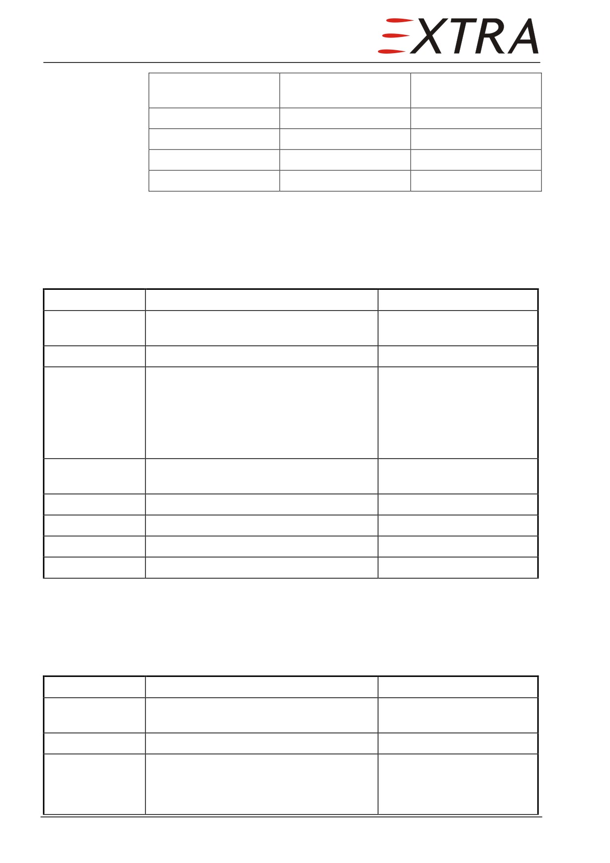
charged and operating, observe the suction and discharge pressures. Typical
values at various ambient temperatures, with hot cabins are shown below:
Page Date:
21 Page 23
OAT
Suction pressure
Discharge pressure
(°C)
(psig)
(psig)
20
28
112
25
30
133
30
31
156
35
32
180
21-50-01
Compressor/Condenser
Removal/Installation
Detail Steps/Work Items
Key Items
1
Ensure BATT switch is OFF and no external
power connected.
2
Remove tail cone access panel.
Refer to Chapter 51-00-01
3
Remove the refrigerant from the air
Refer to Enviro Systems
conditioning system
General Operating, Servicing
and Maintenance Manual for
Airborne R-134a Air-
conditioning Systems
(LOAP 13)
4
Remove all avionic boxes, which may block
XPDR, DME, amplifier
removal of compressor/condenser.
5
Remove refrigerant hoses.
6
Remove air hoses.
7
Remove compressor/condenser.
4 mounting screws
8
Reverse procedure for installation.
21-50-02
Evaporator
Removal/Installation
Detail Steps/Work Items
Key Items
1
Ensure BATT switch is OFF and no external
power connected.
2
Remove tail cone access panel.
Refer to Chapter 51-00-01
3
Remove the refrigerant from the air
Refer to Enviro Systems
conditioning system
General Operating, Servicing
and Maintenance Manual for
Airborne R-134a Air-
Page 24 21
Page Date:
Detail Steps/Work Items
Key Items
conditioning Systems
(LOAP 13)
4 (front
Set the co-pilot seat in the most forward
evaporator only)
position.
5 a (front
Remove side paneling.
Refer to Chapter 25-00-01
evaporator)
5 b (aft
Remove aft paneling.
Refer to Chapter 25-00-01
evaporator)
6
Remove refrigerant hoses.
7
Remove air hoses.
8
Cut electrical wires.
Reconnect later by splicing.
9
Remove mounting screws and remove
evaporator.
10
Reverse procedure for installation.
21-50-03
Soft Start Module
Removal/Installation
Detail Steps/Work Items
Key Items
1
Ensure BATT switch is OFF and no external
power connected.
2
Remove tail cone access panel.
Refer to Chapter 51-00-01
3
Disconnect 3 power lines.
4
Cut control line.
Reconnect later by splicing.
5
Remove soft start module.
4 mounting bolts
6
Install in reverse sequence of removal.
Ensure cable clamps are
installed.
Page Date:
21 Page 25
21-60-00
TEMPERATURE CONTROL
Description
Refer to Figure 21-1.
The system consists of a temperature controller, a cabin temperature sensor, a
duct temperature sensor, a temperature modulating valve, a temperature switch,
the BLEED OVERTEMP warning light and the TEMP CTRL switches and rheostat
on the left side panel.
With the ENV AIR switch ON environmental bleed air is provided for cabin
heating purposes. The bleed air, exiting the engine is too hot to be used for
cabin heating without prior cooling. The amount of cooling required is
dependent on ambient temperature, airspeed, engine power setting, desired
cabin temperature and adequate changes if these parameters change.
Cooling effectiveness is controlled by routing the environmental bleed air
through the air-to-air cooler or directly (bypass) to the cabin by means of the
temperature modulating valve. Operating mode of this valve is selected by the
controls grouped in the CABIN section of the left side panel. With the TEMP
CTRL switch being set to the AUTO position the computerized cabin
temperature controller compares the actual cabin temperature (measured by a
sensor in the cockpit ceiling) to the selected temperature. The temperature
controller is installed inside the cabin behind the side paneling between the
cabin door and the pilot’s seat. Selection is being done by means of the cabin
temperature rheostat also located in the left side panel CABIN section.
Adjustment range is between 13 °C and 30 °C (55 °F to 86 °F). Depending on
the difference between actual cabin temperature and selected cabin temperature
the controller determines a desirable cabin inflow temperature for the
environmental bleed air. The actual inflow temperature is measured by a sensor
located within the bleed ducting prior to cabin entry through the front pressure
bulkhead.
The temperature controller compares this actual inflow temperature to the
desired inflow temperature and adjusts the temperature modulating valve to
match this desired inflow temperature.
It is within the nature of this design (bleed air cooling by means of an air to air
heat exchanger) that cabin bleed air cannot be cooled below ambient
temperature before entering the cabin. Therefore a vapor cycle air conditioning
system (refer to Section 21-50) provides additional cooling capacity for hot
ambient conditions.
The automatic temperature control limits cabin inflow temperatures to values
below 72 °C. An additional independent thermal switch installed in the cabin
distribution valve activates the red BLEED OVERTEMP warning light located on
the annunciator panel in case the cabin inflow temperature exceeds 85 °C. In
case, the BLEED OVERTEMP warning light on the annunciator panel
illuminates, indicating a temperature controller failure, the temperature can be
manually controlled by switching the TEMP CTRL switch, to the MANUAL
position.
Page 26 21
Page Date:
Selected and held in COOL or WARM position activates the temperature
modulating valve manually (overrides the controller) causing warm up or cool
down of incoming bleed air.
21-60-01
Temperature Switch
Removal/Installation
Detail Steps/Work Items
Key Items
1
Ensure BATT switch is OFF and no external
power connected.
2
Remove RH IFD and RH part of main
Refer to Chapter 31
panel.
3
Remove attachment bolts of distribution
To allow moving the
valve.
distribution valve.
4
Move the distribution valve up some
centimeters.
5
Cut the electrical wiring from the
Reconnect later by splicing.
temperature switch
6
Remove temperature switch from the
distribution valve.
7
Install in reverse sequence of removal.
Function Test
Detail Steps/Work Items
Key Items
1
Ensure BATT switch is OFF and no external
power connected.
2
Remove RH IFD.
Refer to Chapter 31-60-01
3
Disconnect LH SCEET hose from the cabin
Worm drive hose clamp
distribution valve.
4
Place BATT switch to ON position.
5
Place NIGHT/DAY switch to TEST position.
To ensure annunciator lights
are OK.
6
Apply hot air to the temperature switch.
More than 85 °C.
Use a blow dryer.
7
Check BLEED OVERTEMP illuminates.
Replace temperature switch if
necessary.
8
Place BATT switch to OFF position.
9
Reinstall SCEET hose.
Page Date:
21 Page 27
Detail Steps/Work Items
Key Items
9
Reinstall RH IFD.
Refer to Chapter 31-60-01
10
Perform pitot/static test.
According to FAR 43,
Appendix E and AC 43.13-
1B CHG1 (or later) § 12-59
21-60-02
Duct Temperature Sensor
Removal/Installation
The duct temperature sensor is attached to the valve box on the RH upper
firewall with 4 bolts and nuts. To make the nuts accessible the forward hose
and the flange have to be removed.
Detail Steps/Work Items
Key Items
1
Ensure BATT switch is OFF and no external
power connected.
2
Remove LH and RH engine cowling.
Refer to Ch. 71-10-01/02
3
Disconnect the forward SCEET hose from
Worm drive hose clamp,
the valve box.
safety wire
4
Remove flange from the valve box.
4 nuts
5
Disconnect electrical connector from the
Bayonet nut
temperature sensor.
6
Remove temperature sensor.
4 bolts and nuts
7
Install in reverse sequence of removal.
Observe the following step.
Refer to Product Label and Material Safety Data Sheet for health and
WARNING
safety information before using PR812.
8
Seal flange with PR812.
21-60-03
Cabin Temperature Sensor
Removal/Installation
Detail Steps/Work Items
Key Items
1
Ensure BATT switch is OFF and no external
power connected.
2
Remove paneling above pilot seat.
Refer to Chapter 25
3
Disconnect electrical wiring from the cabin
temperature sensor.
Page 28 21
Page Date:
Detail Steps/Work Items
Key Items
4
Remove sensor.
4 nuts
5
Install in reverse sequence of removal.
21-60-04
Temperature Controller
Removal/Installation
Detail Steps/Work Items
Key Items
1
Ensure BATT switch is OFF and no external
power connected.
2
Remove left side cabin paneling.
Refer to Chapter 25.
3
Disconnect the electrical wiring from the
temperature controller.
4
Remove temperature controller.
4 attachment screws
5
Install in reverse sequence of removal.
Page Date:
21 Page 29
Chapter 22
Auto Flight
22 Page 1
Table of Contents
22-00-00
GENERAL
5
22-10-00
AUTOPILOT
.................................................................................................... 6
Description.......................................................................................................... 6
Figure 22-1
Autopilot Installation
.......................................................................................... 8
System Components
........................................................................................... 9
Troubleshooting
11
Heading Calibration
12
22-10-01
Roll Servo
13
Removal
13
Figure 22-2
Roll Servo Installation
14
Installation
15
Function Test
15
22-10-02
Pitch Servo
16
Removal
16
Figure 22-3
Pitch Servo Installation
17
Installation
18
Function Test
19
22-10-03
Yaw Servo
19
Removal
19
Figure 22-4
Yaw Servo Installation
21
Installation
22
Function Test
22
22-10-04
Clutches (Pitch, Roll and Yaw Servo)
23
Torque Settings
23
Torque Adjustment
24
Figure 22-5
Clutch Torque Adjustment
24
22-10-05
Driving Wheels
25
Removal/Installation
25
22-10-06
Bridle Cables
25
Removal/Installation
25
Tension Settings
26
Tensioning
26
22-10-07
Cable Clamps
27
Figure 22-6
Cable Clamp Torquing
27
22-10-08
Trim Servo
27
Removal/ Installation
27
Function Test
27
22-10-09
Trim Servo Clutch
28
Torque Settings
28
Torque Adjustment
28
Page 2 22
22-10-10
Pressure Transducer
.......................................................................................29
Removal/Installation
.........................................................................................29
22-10-11
Yaw Amplifier
.................................................................................................30
Removal/Installation
.........................................................................................30
22-10-12
Programmer/Computer
..................................................................................30
Removal/Installation
.........................................................................................30
22-10-13
Turn Coordinator............................................................................................30
Removal/Installation
.........................................................................................30
22 Page 3
22-00-00
GENERAL
This chapter describes the features and functions of the System 55X Two and a
half Axis Autopilot and gives information on basically required maintenance
practices as well as related system components.
22 Page 5
22-10-00
AUTOPILOT
Description
Refer to Figure 22-1. The S-TEC System 55X autopilot system is a rate based
autopilot. Internal signal processing for regulating purposes is mainly analog,
whereas digital electronics is used for the pilot interface and for controlling the
mode of operation.
Pitch and Roll Axis
The signal for the roll servo is generated using the following inputs:
1
Rate of turn information heading bug determined by the Turn Coordinator.
2
Navigation avionics (VOR / LOC, GPS; via IFD).
The signal for the pitch servo is generated using the following inputs:
1
Static pressure (via remote mounted Absolute Pressure Transducer).
2
Sensitive Accelerometer (contained in the Programmer / Computer unit).
3
Altitude Selector (via IFD, key pad or vertical speed knob on A/P computer).
4
Glide Slope Receiver (via IFD).
The autopilot can be activated by means of the
3-position AUTOPILOT
MASTER/FD switch located in the right lower side of the pilot's instrument
panel.
Switching it from the OFF-position to the first stage
(FD) energizes the
autopilot system. The autopilot will start its self-test routine ending up in a
ready mode if performed successfully. This allows the pilot to select the
different operating modes. If appropriate modes are activated set-point steering
commands are shown by the Flight Director symbol displayed in the LH IFD.
The pitch and roll servos are not engaged. Pitch and roll still have to be
controlled by normal steering, using the data provided by the IFD as a set-
actual comparison.
In the second stage (MASTER) the servos are energized and the autopilot
controls pitch and roll axis according to the operating mode(s) selected (refer to
POH).
One possibility to engage the autopilot (both axis) is given by the CWS switch
(control wheel steering) located on top of the right horn of the pilot's control
yoke. This mode engages the autopilot in a way which maintains the actual
pitch and roll attitude (refer to POH).
NOTE
Operation in a pitch mode is possible only if a roll mode is activated.
As a safety device an autopilot quick disconnect switch (AP DISC, red) is also
located in the left horn of the pilot's control wheel to enable the pilot to
disengage the autopilot quickly. Additionally, servo transmissions are designed
as slip clutches, which can be overpowered in any case of failure or
malfunction. The operation mode selection is done via the autopilot main unit
and the IFD or the related keyboard. Indication is made on the autopilot main
unit and the upper LH IFD.
Page 6 22
Trim System
The EXTRA 500 uses a tab at the elevator's trailing edge for pitch trim. This
tab is actuated by a Bowden cable with a special gear located in the horizontal
stabilizer transforming the long travel of the cable into the shorter travel finally
used for tab actuation. The Bowden cable itself may be actuated either by the
pilot using the trim wheel or by the trim servo located on the floor of the tail
cone compartment. The electric trim system may be operated independently
from the autopilot.
When an autopilot pitch mode is active and the electric trim system is switched
on by the TRIM master switch in the pilot's instrument panel, the trim system
operates in the auto trim mode. The pitch servo continuously senses the force
necessary to maintain the assigned pitch attitude and transmits the signal to the
autopilot main unit. This computes a signal to actuate the trim servo. By this
mechanism the force the pitch servo has to apply on the elevator is minimized.
When the autopilot is active (in a pitch mode) and the electric trim servo (TRIM
master switch) is switched off a visual and audible annunciation to the pilot is
provided by the autopilot system asking him to trim the airplane manually by
means of the trim wheel.
With autopilot switched off or no pitch mode engaged, but electric trim servo
(TRIM master switch) on, the longitudinal trim may be adjusted by the pilot
using the momentary split rocker switch on top of the left horn of the pilot's
control yoke.
Yaw Damper
The yaw damper system consists of two units, the yaw servo actuating the
rudder control cables and the yaw amplifier, which generates the signal for the
servo. The amplifier is installed behind the aft pressure dome in the tail cone
compartment. The amplifier features an integrated lateral acceleration sensor.
This sensor detects lateral components of the gravity vector, which corresponds
to the “ball not being centered”. Based on this input signal the yaw amplifier
derives the control signal for the yaw servo.
To allow for a fine adjustment of slip/skid angle, a yaw trim potentiometer
allows the pilot to adjust (“trim”) the zero yaw angle based on a slip/skid
indicator.
In the OFF position of the yaw damper control switch the yaw damper is not
engaged and the yaw servo clutch remains open. With the switch in ON
position the yaw damper remains engaged as long as the autopilot is engaged in
a roll mode. A roll signal from the autopilot main unit is provided to the yaw
amplifier as an additional input (to the lateral acceleration sensed internally).
Yaw damper disconnect is provided by the same means as the autopilot
disconnect as the autopilot main unit provides a yaw damper enable signal to
the yaw amplifier as long a roll mode is active. As soon as the autopilot
disconnects the yaw damper follows therefore.
22 Page 7

Figure 22-1
Autopilot Installation
Page 8 22
System Components
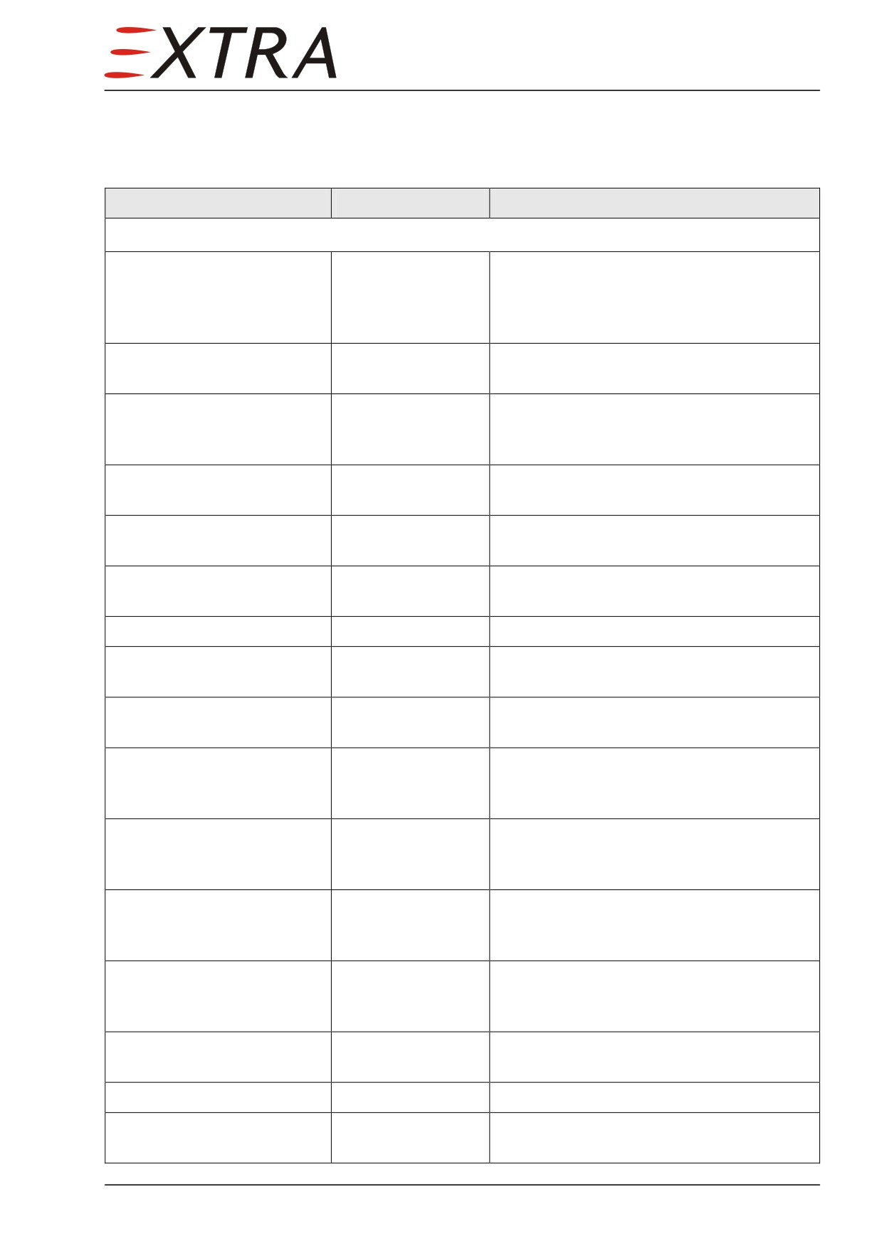
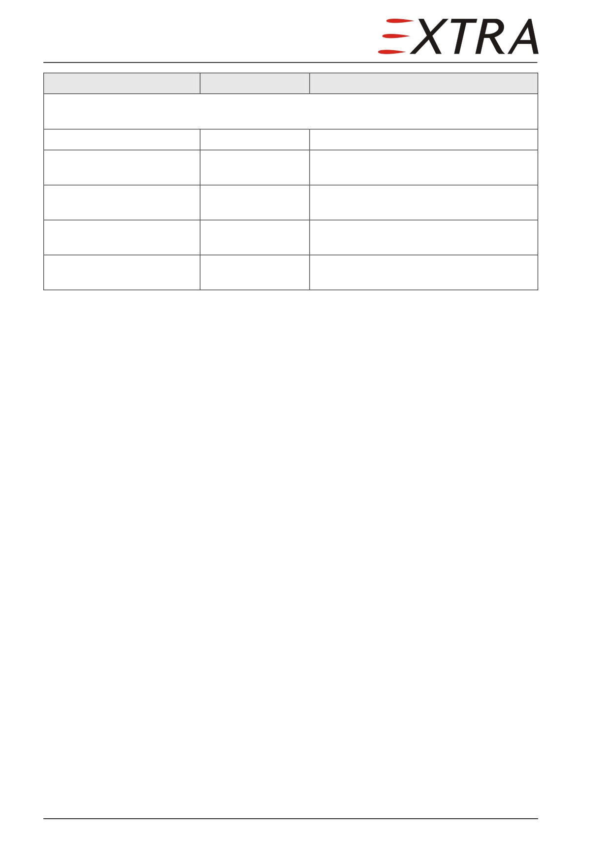
The following components are used in the S-TEC 55 installation of the
EXTRA 500:
Unit Designation
Location
Function
Autopilot Components
Programmer/Computer
Instr. Panel
Pilot interface
(P/C)
signal generation for roll, pitch and pitch
(special configuration for
trim servo
EXTRA 500)
Yaw amplifier
Tail cone equipment
Yaw sensor & signal generation for yaw
rack
servo
Turn Coordinator
Instr. Panel
Sensing rate of turn,
input signal for P/C,
indication to pilot
Absolute pressure Transducer
Tail cone equipment
Converting static pressure => electric signal
rack
Roll Servo
Front wing
Aileron actuation
compartment
Pitch Servo
Tail cone equipment
Elevator actuation, force sensing for trim
rack
system
Pitch Trim Servo
Tail cone floor
Trim tab actuation
Yaw Servo
Tail cone equipment
Rudder actuation
rack
Autopilot Relay
behind instrument
Connecting inputs to A/P computer from
panel
either IFD 1 or IFD 2
Autopilot Master Switch
Autopilot Panel
Activation of autopilot and / or flight
(Pilot Instrument
director
Panel)
Pitch Trim Switch
Autopilot Panel
Activation of electric pitch trim System
(Pilot Instrument
Panel)
Yaw Damper Master Switch
Autopilot Panel
Activation of yaw damper
(Pilot Instrument
Panel)
Yaw Trim Knob (rotary
Autopilot Panel
Adjustment of zero jaw attitude
Potentiometer)
(Pilot Instrument
Panel)
Trim command Switch
Control Wheel
Change of aircraft pitch trim
(split switch)
CWS-Switch
Control Wheel
Engaging CWS-mode
Autopilot disconnect / trim
Control Wheel
Disengaging autopilot, interruption of
interrupt switch
electric trim actuation
22 Page 9
Unit Designation
Location
Function
Closely related systems/components
Audio Panel
Instrument panel
Audible warnings from P/C
IFD 1
Instrument panel
Source for heading and course, vertical
speed command, Flight Director display
IFD 2
Instrument panel
Source for heading and course, vertical
speed command, flight director display
Keypad
Center console
Altitude and heading selection, inputs to
IFDs
Stall warning switch
LH wing leading
Disconnect of A/P when stall warning
(“Lift Detector”)
edge
becomes active
Page 10 22
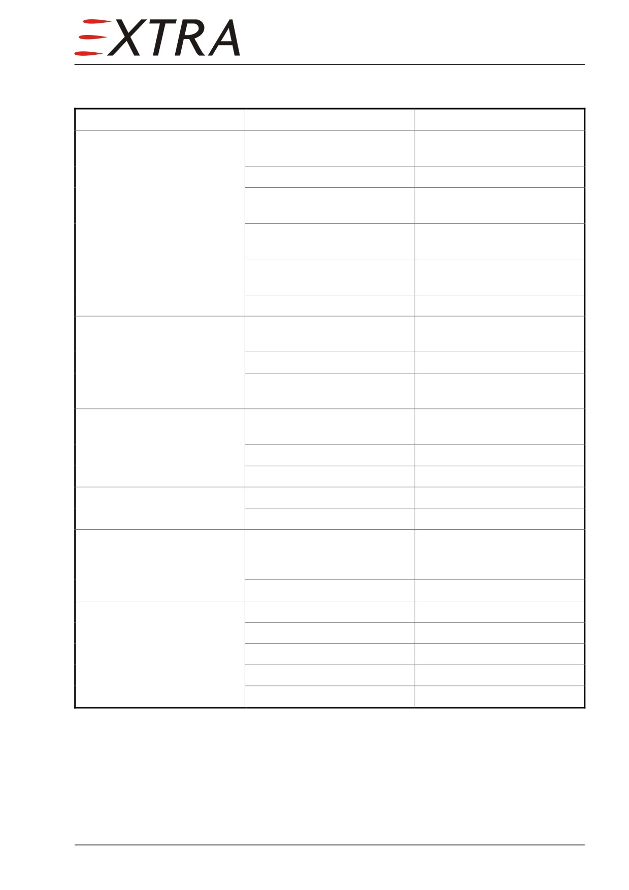
Troubleshooting
Complaint
Possible Cause
Remedy
Autopilot will not engage in
Autopilot has no power
Check AUTOPILOT MASTER
any mode
switch FD or MASTER.
Autopilot has no power
Check AVIONICS switch ON.
No valid signals from turn
Check turn coordinator no
coordinator
flag.
AP disconnect switch
Check AP disconnect switch
struck/defective
continuity.
Pitch trim switch
Check pitch trim switch stuck.
stuck/defective
Computer defective
Replace computer.
Will not engage in any altitude
No roll mode engaged
A roll mode MUST be
mode
selected first
Computer defective
Replace computer.
No valid signal from absolute
Replace absolute pressure
pressure transducer
transducer.
CWS does not work
Autopilot not coupled in both
An altitude and roll mode
axes
must be engaged previously.
Switch defective
Replace CWS switch.
Computer defective
Replace computer.
AP disconnect switch does not
Switch defective
Replace AP disconnect switch.
work
Computer defective
Replace computer.
Mode engages, but servo does
AP in FD mode
Check AUTOPILOT MASTER
not couple
switch in MASTER position
(not FD)
Servo defective
Replace servo.
Electrical Pitch trim does not
Pitch system has no power
Check battery bus power.
work
Pitch system has no power
Check pitch trim switch ON.
Pitch trim switch defective
Replace pitch trim switch.
Computer defective
Replace computer.
Pitch trim servo defective
Replace pitch trim servo.
22 Page 11
Complaint
Possible Cause
Remedy
Yaw trim does not work
No power to yaw amplifier
Check battery bus power
YAW DAMPER switch OFF.
YAW DAMPER switch ON.
Yaw damper switch defective
Replace yaw damper switch.
No roll mode enabled
Engage roll mode first.
Yaw amplifier defective
Replace yaw amplifier.
Yaw servo defective
Replace yaw servo.
Yaw trim poti defective
Replace yaw trim
potentiometer.
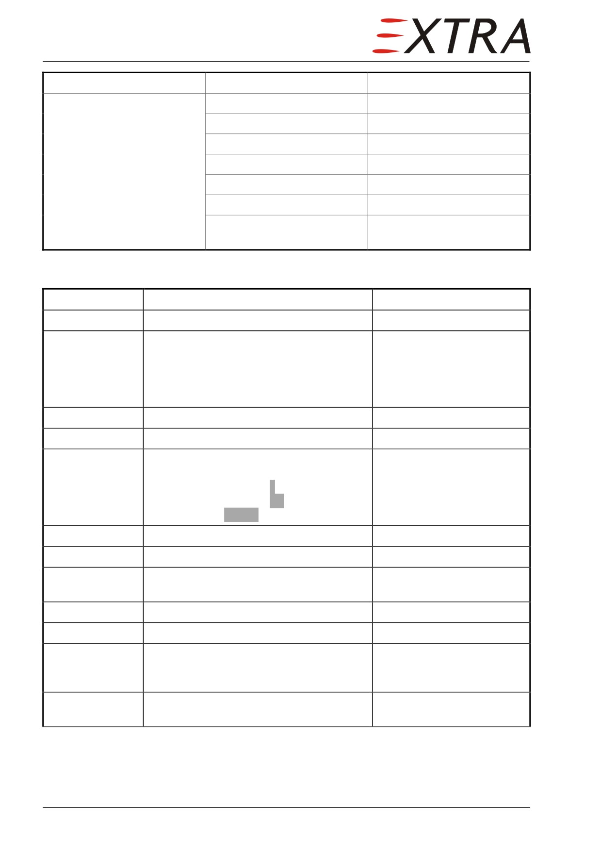
Heading Calibration
Detail Steps/Work Items
Key Items
1
Attach external power.
2
Check all switches OFF,
A/P CMPTR CB IN,
Turn-Coord CB IN,
A/P SERVO CB IN,
All IFD CB-s IN
3
Switch on EXT PWR
4
Switch on AUTOPILOT - MASTER
5
Check turn coordinator runs up,
off-flag disappears,
Autopilot display shows 7 on display,
Autopilot display shows rdy,
LH IFD shows AP RDY
6
Wait for 2 minutes
to let turn coordinator run up
7
Set IFD to NAV I
8
Tune NAV I to a frequency that has no
reception
9
Set heading bug to current heading
push heading knob on keypad
10
Select NAV mode on autopilot
11
Adjust the potentiometer between the REV
use miniature flat screwdriver
and ALT buttons in small increments until
the yoke stops turning
12
Make sure in the end the AP is in SOFT
indicated on IFD
mode
Page 12 22