Extra 500. Maintenance Manual (2012) - page 7
24-00-00
GENERAL
Description
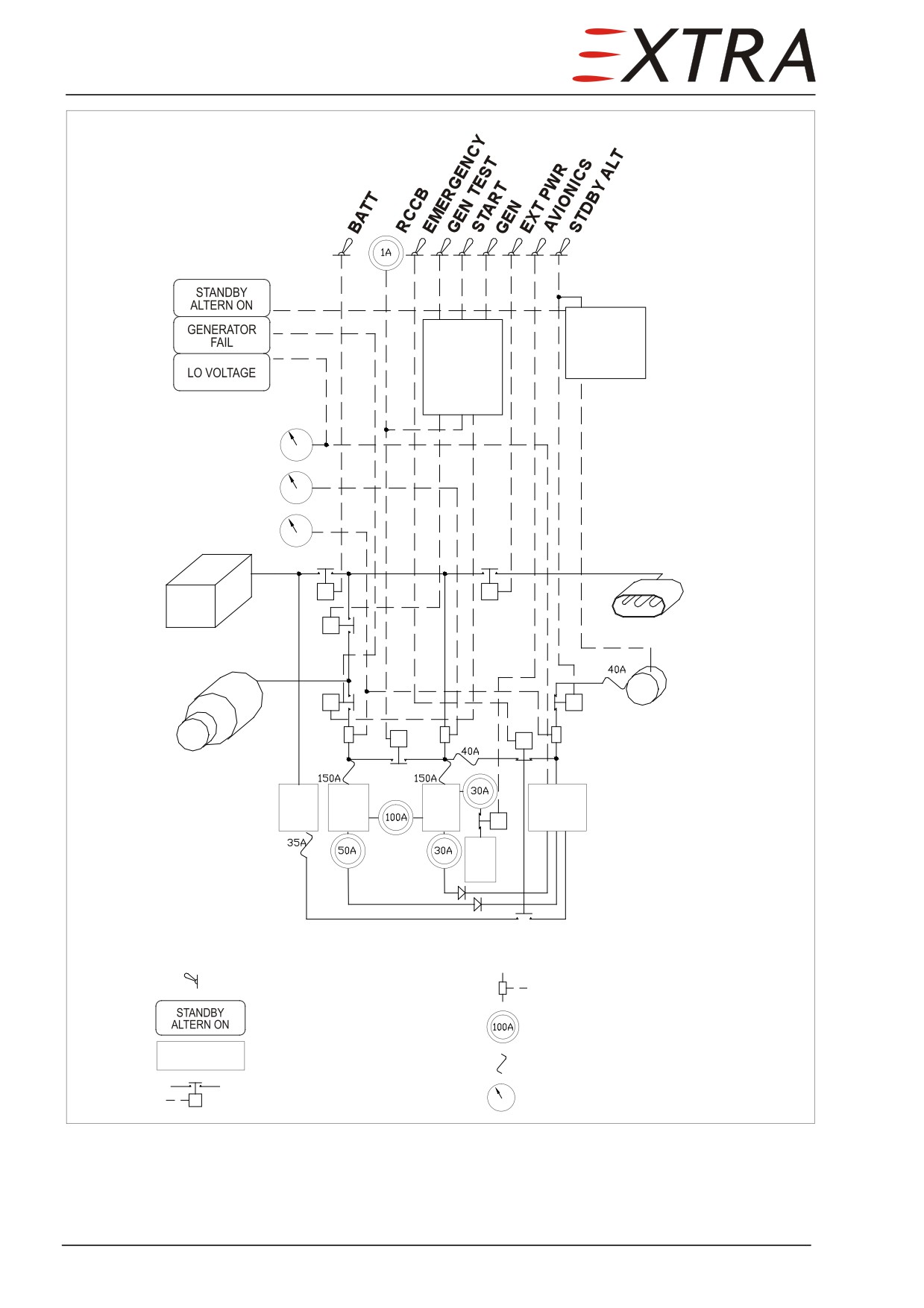
Refer to Figure 24-1. The electrical system is a 28 VDC system with negative
ground. The primary DC power source is an engine driven 28 V/200 A starter-
generator. It is backed up by an engine driven 26 V/20 A standby alternator. In
addition a lead acid battery
(24 V/28 Ah) is installed in the engine
compartment. Normal battery power is sufficient to start engine or for ground
check operation.
An external 28 VDC power receptacle and its circuit breaker are installed in a
hatch right hand at fixed portion of the cowling.
24 Page 3
y
Alternator
r
Generator
control
unit
control
y
unit
Bus voltage
Battery current
Generator current
External power
Battery
24 VDC
Standby alternator
20 A
Starter/generator
200 A
Hot
Load
Batt.
Emerg.
bus
bus
bus
bus
AV
bus
Legend:
Switch
Shunt
y
Annunciator light
Circuit breaker
Hot bus
Electrical bus
Fuse
Relay
Gauge
Figure 24-1
Electrical System Schematic
Page 4 24
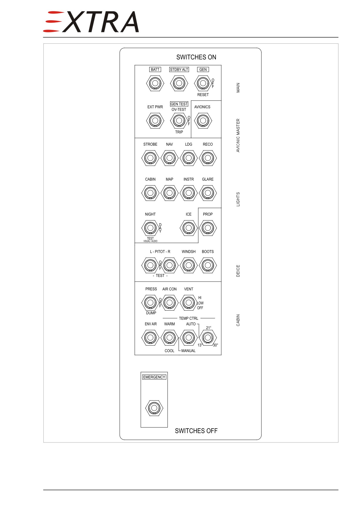
Figure 24-2
Left Side Panel Switches
24 Page 5
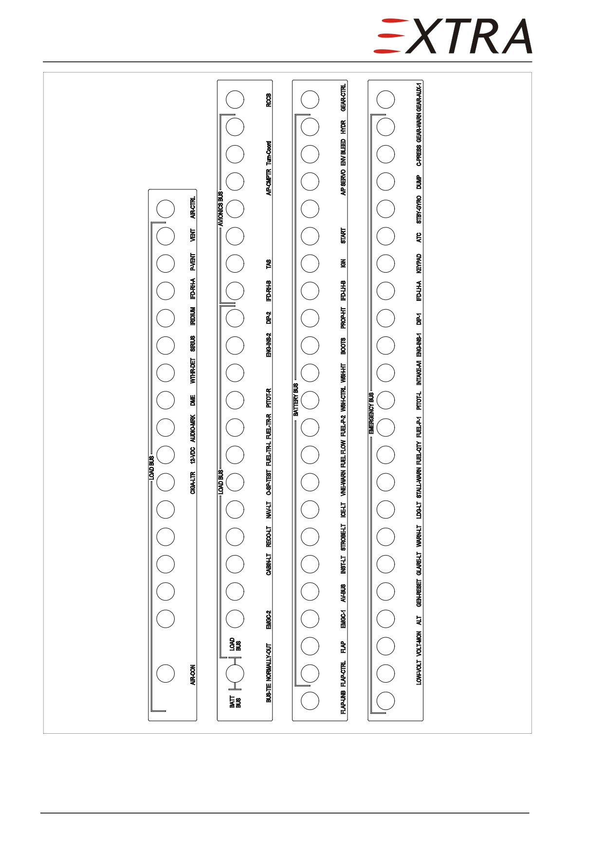
Figure 24-3
Left Side Panel Circuit breakers
Page 6 24
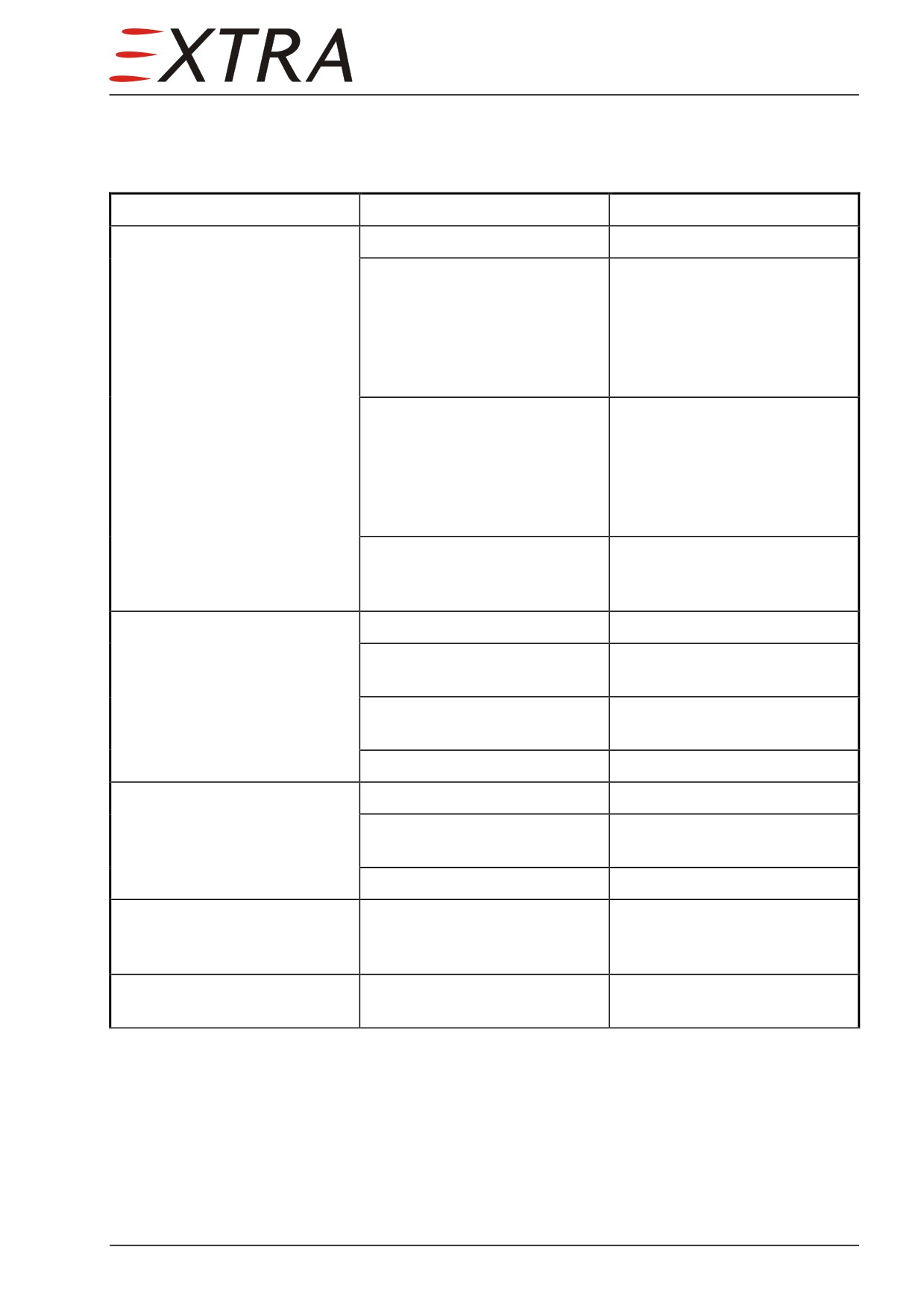
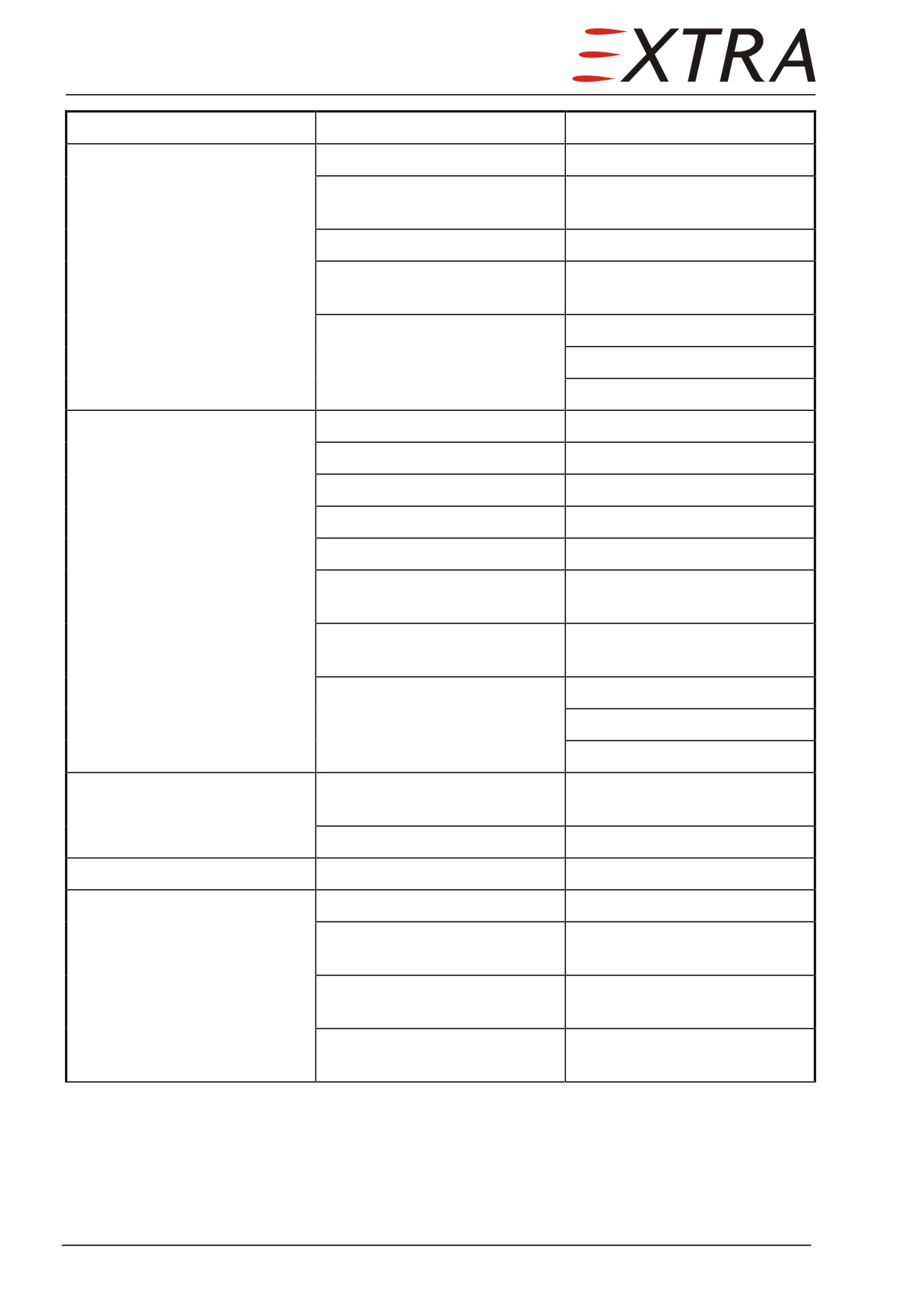
Troubleshooting
The following paragraph tabulates the trouble shooting procedures relevant to
the battery system.
Complaint
Possible Cause
Remedy
System not energized when
Depleted or dead battery
Recharge or replace.
battery switch is turned on
Defective wiring
With BATT switch OFF, check
entire DC power system,
accessible from plane fire wall
resp. lower tail cone access
panel, for an open circuit with
a continuity tester
Defective battery relay
With BATT switch ON,
connect a voltmeter to the
main battery bus and check
voltage. If no voltage is
indicated, check and/or replace
relay
Defective BATT switch
Remove switch and check
with continuity tester. Replace
switch if defective.
Battery discharged
Charging rate too low
Check generator
Battery has been left standing
Recharge or replace
too long without recharging
Equipment has been left on
Replace battery
accidentally
Short circuit in wiring
Check wiring, replace battery.
Short battery life
Low charging rate
Check generator voltage
Corroded or loose battery
Clean and tighten, recharge
connections
battery.
Reduced battery capacity
Replace battery.
Battery polarity reversed
Connected backwards on
Battery should be slowly
airplane or charger
discharged completely, then
charged correctly and tested
Battery freezes
Undercharged or overcharged
Replace battery
battery
24 Page 7
Complaint
Possible Cause
Remedy
Starter-generator does not
Starter-generator defective
Replace starter-generator.
produce current when
Generator control unit
Replace generator control unit.
switched on.
defective
GEN switch defective
Replace GEN switch.
Generator relay defective
Replace generator relay (E-
box).
Current indication defective
Replace shunt.
Replace indicator.
Repair wiring.
Standby alternator does not
Bus voltage above 26.5 V
Normal, no action required.
produce power when switched
Alternator defective
Replace alternator.
on
Alternator controller defective
Replace alternator controller.
Wiring defective
Repair wiring.
STDBY ALT switch defective
Replace STDBY ALT switch.
Alternator relay defective
Replace alternator relay (E-
box).
Alternator fuse defective
Examine reason and replace
alternator fuse (E-box).
Current indication defective
Replace shunt.
Replace indicator.
Repair wiring.
Load bus without power
Starter-generator or external
Normal, no action required.
power not on.
Load bus fuse defective
Replace fuse (E-box).
Battery bus without power
Battery bus fuse defective
Replace fuse (E-box).
Avionic bus without power
Battery bus without power
See above.
AVIONICS switch defective
Replace AVIONICS switch (left
side panel).
Avionic bus relay defective
Replace avionic bus relay (left
side panel).
AV BUS circuit breaker
Replace AV BUS circuit
defective
breaker (left side panel).
Page 8 24
24-30-00
DC GENERATION
Refer to Figure 24-1.
DC generation is done by the following devices:
• Starter-generator
• Standby Alternator
• Battery
24-30-10
Starter-Generator
A starter-generator is mounted on the accessory gearbox of the engine. It is a
direct driven starter during engine start and a DC generator driven by the
engine during engine operation. Its rated capacity is
200 A maximum for
continuous operation.
Removal/Installation
Remove the LH upper engine cowling to get access to the starter-generator.
Refer to AIRCRAFT PARTS CORP. Installation Instructions 200SGL Series
Starter-Generators (LOAP 39) for further information.
24-30-11
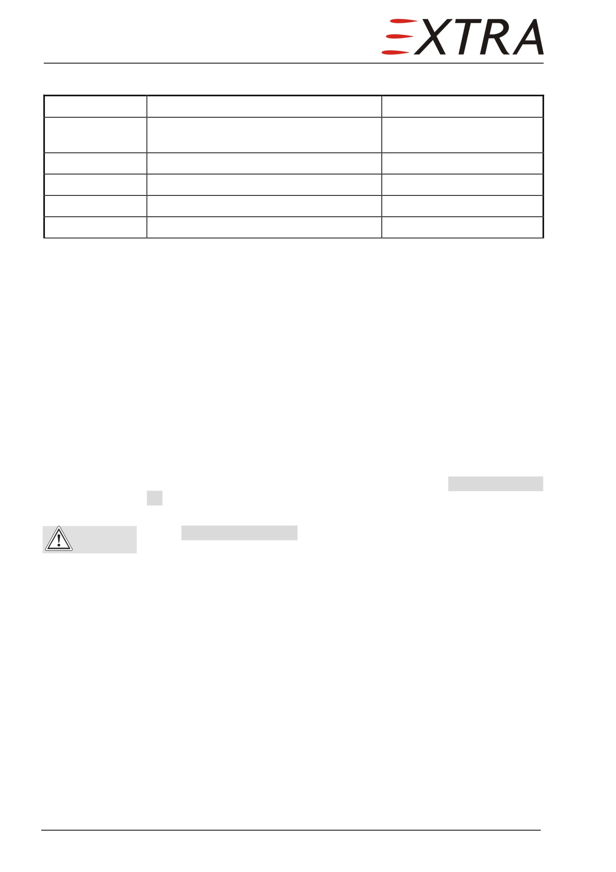
Generator Control Unit (GCU)
The starter-generator is regulated by the GCU (Generator Control Unit) to
provide an output voltage of 28.5 V DC. The GCU is installed to the fuselage
structure behind the left legroom side paneling. The GCU is controlled by the
GEN and GEN TEST switches located on the MAIN section of the left side panel.
Following engine start, the generator delivers electrical power when the GEN
switch is switched to ON position.
In case the generator is not switched on or has failed the red GENERATOR FAIL
warning light on the annunciator panel illuminates. With the generator test
switch (GEN TEST, left side panel) the overvoltage protection function of the
GCU can be tested (switch position: OV-TEST). The TRIP position of this
switch gives the possibility to “trip” the generator by momentarily interrupting
its excitation. Both test functions lead to disengagement of the generator from
the aircraft bus system. The momentary RESET position of the GEN switch
serves to energize the generator field in case problems have occurred trying to
connect the generator to the aircraft bus system (switching the generator ON).
Resetting the generator is recommended in that case before trying to switch the
generator on again.
24 Page 9
Removal/Installation
Detail Steps/Work Items
Key Items
1
Ensure BATT switch is OFF and no external
power connected.
2
Remove left legroom side paneling.
Refer to Chapter 25-00-01.
3
Remove electrical connector.
4
Remove GCU.
4 bolts
5
Install in reverse order of removal.
24-30-20
Standby Alternator
In case of a starter-generator failure a gear driven standby alternator provides
an additional power source in excess to the aircraft battery. The standby
alternator is controlled by the STDBY ALT switch in the MAIN section of the
left side panel. Switching it to the ON position will command the alternator
regulating unit to regulate an alternator output voltage of 26 VDC. Therefore as
long as bus voltage is higher caused by an active generator the alternator load
will be zero. As soon as bus voltage drops below the regulation voltage of the
standby alternator the alternator feeds to the bus system. Max. rated current is
20 A which is available with N1 being at approx 92 %. At 78 % N1 about 10 A
are available. Below 70 % N1 the standby alternator isn’t able to provide a
relevant current.
Operation of the standby alternator is indicated by a yellow STANDBY ALTERN
ON caution light on the annunciator panel. Continuous illumination of this light
signals operation below the 20 A output limitation.
If the STANDBY ALTERN ON caution light starts blinking, the load on the
CAUTION
alternator exceeds its rated capacity. Reduce consumption of electrical
consumers within 5 minutes to 20 A or less.
Removal/Installation
Remove the upper engine cowlings to get access to the stand-by alternator.
Refer to B & C SPECIALTY PRODUCTS Installation Instructions for BC410
Alternators (LOAP 40) for further information.
24-30-21
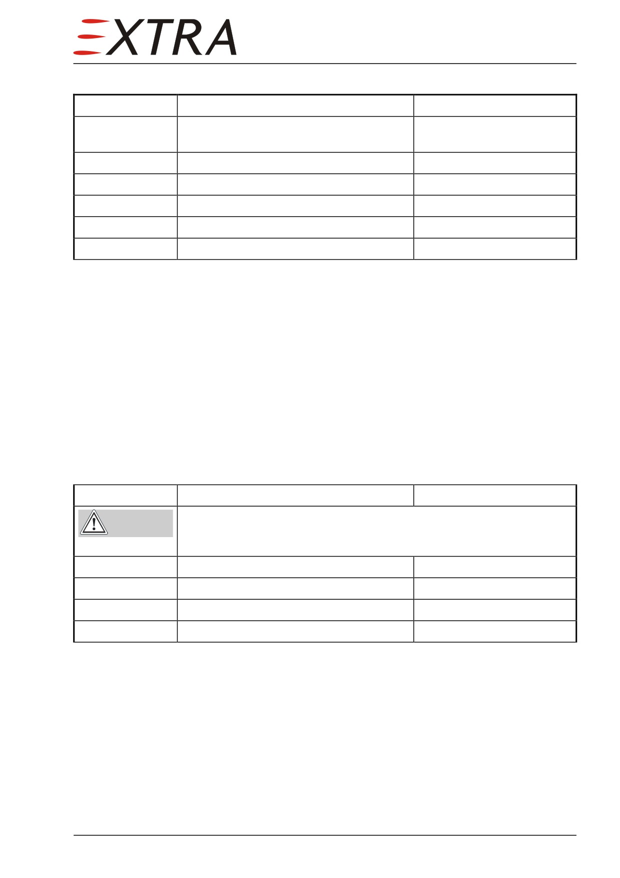
Alternator Regulator
The alternator regulator is mounted to the cabin side of the firewall.
Refer to B & C SPECIALTY PRODUCTS B & C SPECIALTY PRODUCTS
Troubleshooting Guide (LOAP 28) for further information.
Page 10 24
Removal/Installation
Detail Steps/Work Items
Key Items
1
Ensure BATT switch is OFF and no external
power connected.
2
Remove RH and LH IFD.
Refer to Chapter 31-60-01.
3
Remove electrical connection.
4
Remove 2 nuts.
5
Remove regulator.
6
Install in reverse order of removal.
24-30-30
Battery
The 24 VDC/28 Ah valve regulated lead acid battery is located in the engine
compartment, mounted to the pressure bulkhead and protected by a vented
aluminum case. The battery is directly connected to the hot bus. The battery
supplies power to the electrical system when BATT switch is switched to ON
position.
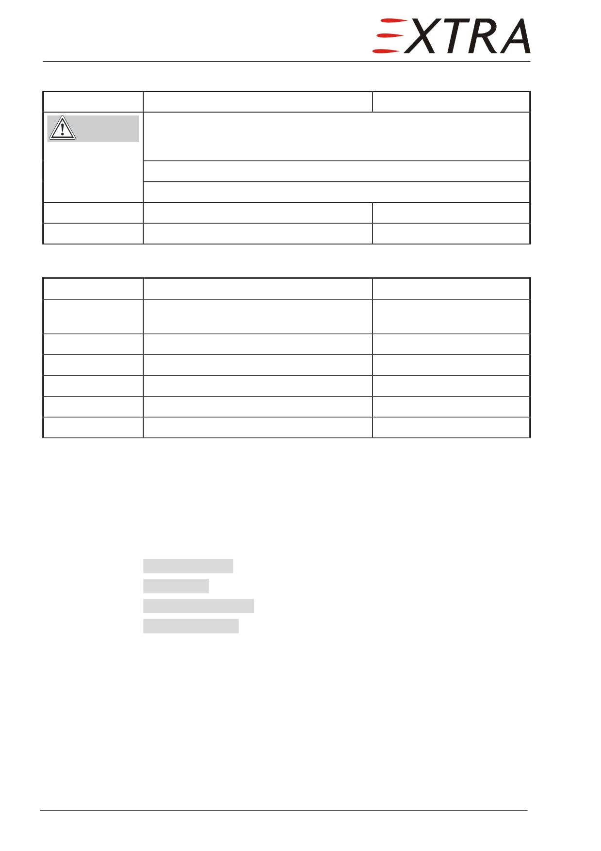
Recharging the battery may be done with battery installed. There are two
procedures:
Charging with external power
Detail Steps/Work Items
Key Items
Always keep sparks or any form of ignition away from the battery being
WARNING
charged. Explosive gases are being generated during the charging
process.
1
Set external power unit to 28 VDC.
2
Connect external power.
3
Switch on BATT.
4
Switch on EXT PWR.
24 Page 11
Charging over charger plug
Detail Steps/Work Items
Key Items
Always keep sparks or any form of ignition away from the battery being
WARNING
charged. Explosive gases are being generated during the charging
process.
Do not charge with more than 5 A.
Use only supplied unit or equivalent.
1
Connect the charger to the charger plug.
2
Connect the charger to the wall socket.
Removal/Installation
Detail Steps/Work Items
Key Items
1
Ensure BATT switch is OFF and no external
power connected.
2
Remove upper engine cowlings.
Refer to Ch. 71-10-01/02.
3
Disconnect the quick connect plug.
4
Disconnect the 2 retainers.
5
Remove battery from aircraft.
6
Install in reverse order of removal
24-30-40
Indication
Electric system relevant indication is made by the digital indicator cluster
installed in the left side of the main panel and the following lights in the
annunciator panel:
GENERATOR FAIL (red), see Subject 24-30-10.
LO VOLTAGE (yellow), illuminates as soon as bus voltage drops below 25.5 V.
STANDBY ALTERN ON (yellow), see Subject 24-30-20.
EXTERNAL POWER (green), see Subject 24-40-00.
24-30-41
Indicator Cluster
The digital indicator cluster installed in the left side of the main panel indicates
three electric system parameters among other engine parameters (also refer to
Chapter 77-40-02):
Page 12 24
VDC (bus voltage)
During normal operation (generator active) a voltage of approx 28 V should be
indicated. With standby alternator the indication should be about 26 V. Battery
nominal voltage is 24 V.
GEN AMPS (Generator Load)
Generator load is indicated on this indicator as long as the generator is active
(GENERATOR FAIL warning light off). Generator Load should be kept below
200 A. In case the generator is offline this indicator automatically displays the
standby alternator load. The standby alternator load has to stay below 20 A (see
also Subject 24-30-20).
BAT AMPS
The battery amp indicator shows load or charging current on the battery. A
negative indication means battery is being charged, a positive indication means
battery is discharged (load on battery).
Removal/Installation
For removal/installation procedures refer to Chapter 77-40-02.
24 Page 13
24-40-00
EXTERNAL POWER
Description
An external power receptacle is installed under an access door on the right side
of the engine compartment. The use of external power is recommended for
engine starting in case aircraft battery is weak, for ground operation of the
vapor cycle air condition system or for any prolonged ground operation of
aircraft systems. An external power source being connected with the external
power receptacle and switched on will be indicated by a green EXTERNAL
POWER annunciation light in the annunciator panel. To enable the external
power source to supply power to the aircraft the EXT PWR switch on the MAIN
section of the left side panel has to be switched on.
Do not connect ground power units with a capacity greater than 1200 A
CAUTION for engine start.
NOTE
It is not possible to connect the starter-generator and an external power
source simultaneously to the aircraft bus system. This is to avoid any
uncontrolled currents between these units.
Additionally a battery charger plug is installed at the external power receptacle.
The battery may be charged with 29.0 V and 5 A.
Page 14 24
24-60-00
DISTRIBUTION
Description
Electrical power from the various power sources is supplied to the E-box. The
E-box incorporates the main devices of the distribution system such as fuses,
circuit breakers, relays, and shunts and is installed on the engine side of the
firewall. From there power is distributed partly through individual fuses to the
following buses:
•
Hot Bus,
•
Emergency Bus,
•
Battery Bus and Avionic Bus
•
Load Bus,
The battery directly feeds the hot bus supplying power for equipment, which
has to be independent from the battery switch position (e.g. ELT; see Figure
24-2 for location of battery switch).
Turning the battery switch to the ON-position will activate a relay connecting
the battery to the battery bus and further to the emergency bus. This allows
starting the engine and feeding the other equipment and, if engine is running,
recharging the battery with the starter/generator.
The generator is activated by turning GEN switch to the ON-position (see
Figure 24-2). So the generator is activated and the generator relay connects the
generator to the load, battery and emergency bus.
From the main bus electrical power is distributed to the various busses as
outlined on Figure 24-1. The avionic bus can be disconnected by the AVIONICS
switch.
The main control switches of the electrical power system are located on the
MAIN section of the left side panel (see Figure 24-2) and are marked EXT PWR,
BATT, STBY ALT, GEN and GEN TEST.
Push-pull circuit breakers automatically break the current if an overload occurs
to prevent damage to the electrical wiring and equipment. The most circuit
breakers are installed to the left side panel (see Figure 24-3). A single circuit
breaker is installed on the upper LH engine mount (GCU) and under the
external power hatch (EXT PWR) respectively. All other circuit breakers are
installed to the E-box located on the engine side of the firewall and are labeled
GEAR AUX 2, BATT CHARGE, SPARE, ALT FIELD 2, COURTESY LT, and ELT.
Generally where exclusively wiring shall be protected poly switches are used.
They are installed on different locations of the electrical system.
24 Page 15
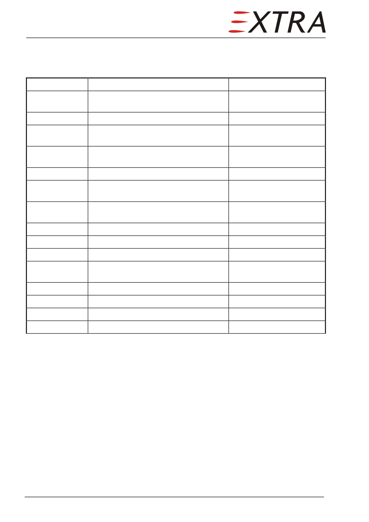
24-60-01
E-box
Removal/Installation
Detail Steps/Work Items
Key Items
1
Ensure BATT switch is OFF and no external
power connected.
2
Remove upper engine cowlings.
Refer to Ch. 71-10-01/02.
3
Disconnect the SCEET hoses from the oil
cooler inlet.
4
Remove 10 attachment screws of the oil
cooler inlet.
5
Remove oil cooler inlet.
6
Remove 8 oil cooler outlet attachment
screws.
7
Move oil cooler and outlet some centimeters
To get access to the E-box.
forward.
8
Disconnect electrical connector
9
Disconnect power lines
10
Remove upper E-box cover.
1 screw
11
Disconnect 3 main power bulkhead feed-
Hold threaded rod in place by
throughs.
means of an Allen wrench.
12
Remove 3 attachment screws.
13
Remove E-box.
14
Remove cover plate and shell plate.
Plates are screwed on.
15
Install in reverse sequence of removal.
24-60-02
Switches
Removal/Installation
The switches on the instrument panel are accessible from the backside after
removal of the RH IFD. The LANDING GEAR, FLAP, and ELT switch
backsides are directly accessible from the legroom.
The backsides of the left side panel switches are accessible when the upper and
lower part of the left side panel has been removed.
Generally conventional switches are used, so that removal is done by
disconnecting the electrical wiring and removing attachment screws or nuts.
Installation is vice versa.
Page 16 24
24-60-03
Circuit Breakers
Removal/Installation
The circuit breakers on the left side panel are accessible from the backside
when the upper and lower part of the left side panel has been removed.
To get access to the E-box circuit breakers the E-box must be removed (refer to
Subject 24-60-01).
Generally conventional circuit breakers are used, so that removal is done by
disconnecting the electrical wiring (busses) and removing attachment screws or
nuts. Installation is vice versa.
24-60-04
Relays
Relays are installed in the left side panel, in the E-box and behind the RH IFD.
To get access to the relays either the E-box (see Subject 24-60-01), the left side
panel (see Chapter 31-10-01) or the RH IFD (see Chapter 31-60-01) must be
removed
Electrical wiring is generally connected to the relays by means of relay sockets.
The relays are mounted to the sockets with bolts.
24-60-05
Shunts
Shunts are installed in the E-box.
To get access to the shunts the E-box must be removed (refer to Subject 24-60-
01).
Electrical wiring is generally connected to the shunts by means of screws. The
shunts are mounted to the supports with bolts.
24-60-06
Fuses
The main fuses are installed in the E-box with bolts. They are accessible after
removal of the upper E-box cover.
24 Page 17
Chapter 25
Equipment and Furnishing
25 Page 1
TABLE OF CONTENTS
25-00-00
GENERAL
5
25-10-01
Paneling
5
Description
5
Removal/Installation
5
25-10-00
FLIGHT COMPARTMENT
6
25-10-10
Seats, Seat Belts, and Shoulder Harnesses
6
Description
6
25-10-11
Pilot's Seat
6
Removal/Installation
6
25-10-12
Copilot's Seat
7
Removal/Installation
7
25-10-21
LH Side Armrest Paneling
7
Removal/Installation
7
25-10-22
RH Side Armrest Paneling
8
Removal/Installation
8
25-10-23
Front Ceiling Paneling
8
Removal/Installation
8
25-10-24
Upper Side Paneling LH/RH Side
9
Removal/Installation
9
25-10-25
Windshield Middle Strut Paneling
9
Removal/Installation
9
25-10-26
Middle Console Paneling Upper Part
9
Description
9
Removal/Installation
9
25-10-27
Middle Console Paneling Lower Part
10
Description
10
Removal/Installation
10
25-20-00
PASSENGER COMPARTMENT
11
25-20-10
Seats
11
25-20-11
Front Passenger Seats
11
Removal/Installation
11
25-20-12
Aft Passenger Seats
11
Removal
11
Installation
12
25-20-21
LH Side Armrest Paneling
12
Removal/Installation
12
Page 2 25
25-20-22
RH Side Armrest Paneling
13
Removal/Installation
13
25-20-31
Storage Boxes LH/RH
13
Description
13
Removal/Installation
13
25-20-32
Table
14
Removal/Installation
14
25-50-00
BAGGAGE COMPARTMENT
15
Description
15
25-50-01
Tie Down Belts
15
Removal/Installation
15
25 Page 3
25-00-00
GENERAL
25-10-01
Paneling
Description
If not described in another way paneling is generally mounted to the aircraft
structure with Phillips screws.
Removal/Installation
Take care of the paneling installations such as switches, sockets, lights etc.
when removing. Ensure BATT switch is OFF and no external power connected,
when electrical devices are involved. Sometimes the paneling overlaps. Then it
is necessary to remove also the adjacent paneling. Move paneling some
centimeters inboard after removal of Philips screws to get access to the
paneling backsides. Then disconnect electrical wiring. Installing is vice versa.
25 Page 5
25-10-00
FLIGHT COMPARTMENT
25-10-10
Seats, Seat Belts, and Shoulder Harnesses
Description
The pilot's and copilot's seats are one piece, four-way adjustable seats
incorporating energy absorbers which reduce forces working on the occupants
in case of crash. The seats may be moved forward, aft, up, and down. The
adjustment is made by pulling a handle located at the right respective left
forward underside of the seat to release the fixing mechanism. The horizontal
adjustment range is 152 mm, 5 fixed positions are provided. The vertical
adjustment range is
80 mm, 5 fixed positions are provided. Telescopic
cylinders support the pilot during the vertical adjustment.
The seat belts and the shoulder harnesses with inertia reels used for the pilot
and copilot are attached to the seats. The seat belts provide a conventional
adjustment. Shoulder harness adjustment is not necessary due to the inertia
reels, which allow straps to extend and retract as required under normal
movement. However the reels will lock in place in the event of a sudden
deceleration.
25-10-11
Pilot's Seat
Removal/Installation
Detail Steps/Work Items
Key Items
1
Remove front roll from RH seat track.
2 screws
2
Remove mounting bracket and roll as
2 screws
a unit from back RH seat track.
3
Pull off bracket from back LH seat
2 screws
track.
4
Pull adjusting handle to release bolt at
longitudinal adjusting device.
5
Slide seat out of mounting console in
forward direction.
6
Install in reverse order of removal.
Page 6 25
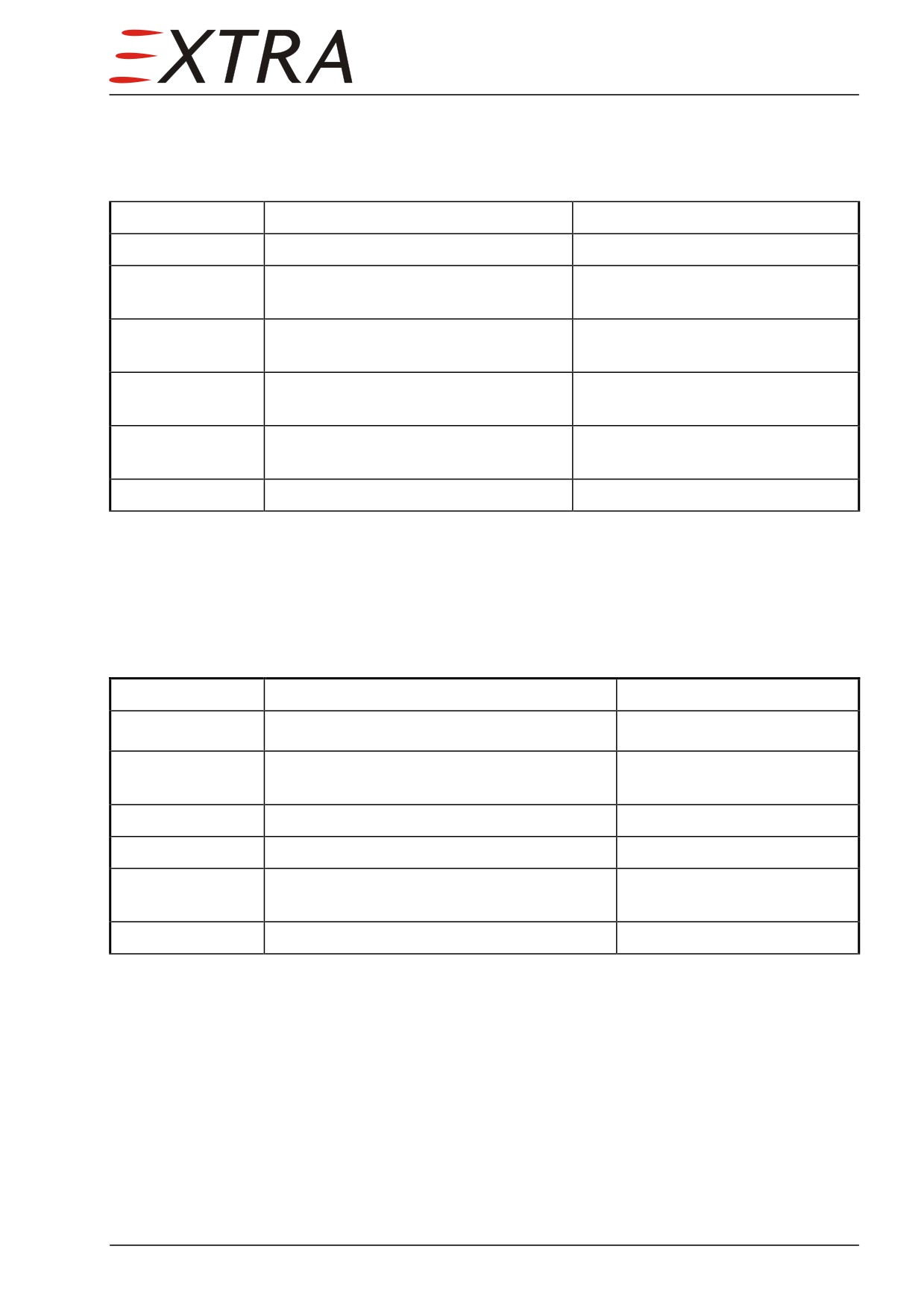
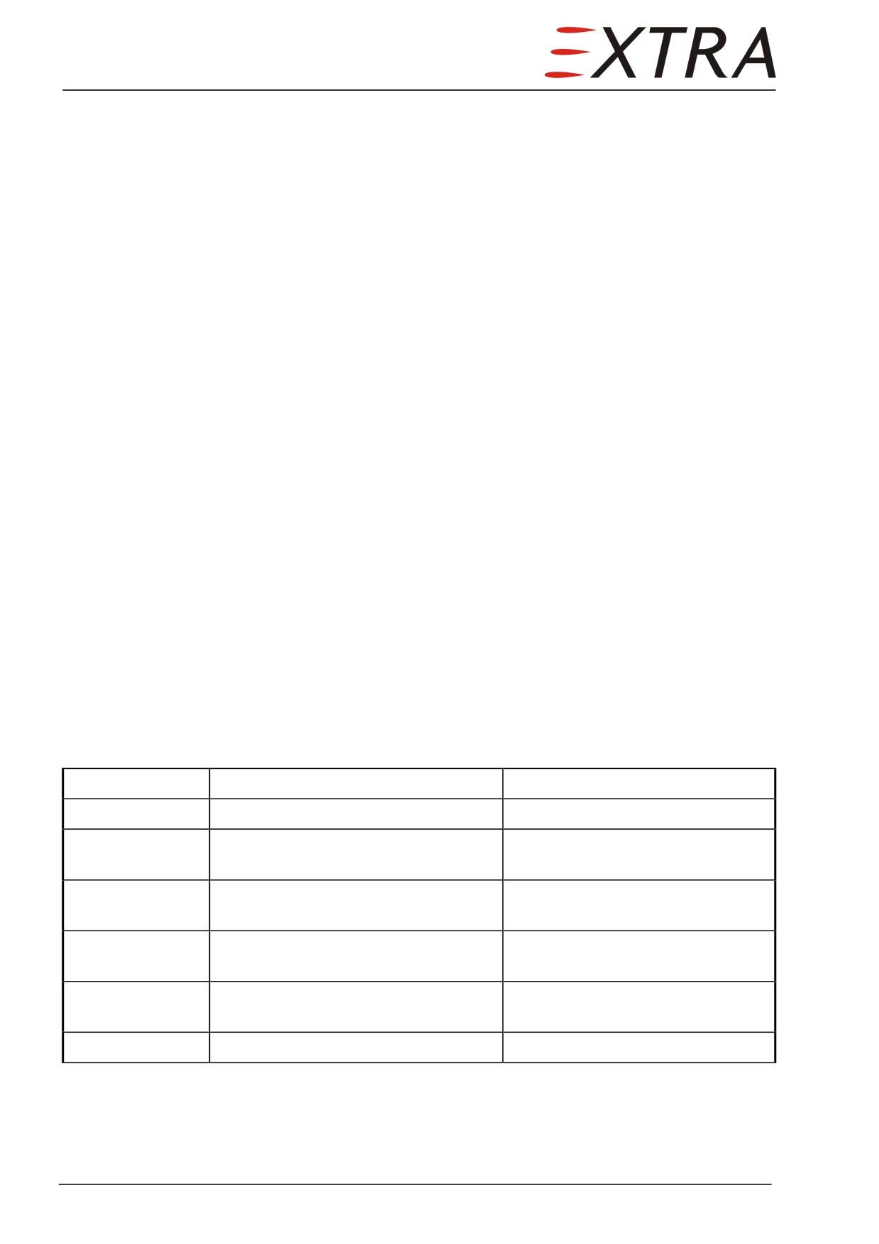
25-10-12
Copilot's Seat
Removal/Installation
Detail Steps/Work Items
Key Items
1
Remove front roll from LH seat track.
2 screws
2
Remove mounting bracket and roll as
2 screws
a unit from back LH seat track.
3
Pull off bracket from back RH seat
2 screws
track.
4
Pull adjusting handle to release bolt at
longitudinal adjusting device.
5
Slide seat out of mounting console in
forward direction.
6
Install in reverse order of removal.
25-10-21
LH Side Armrest Paneling
Removal/Installation
Detail Steps/Work Items
Key Items
1
Remove left side panel.
Refer to Chapter 31-10-01.
2
Remove screw fastening microphone twin
socket on rear top of panel.
3
Remove screw at lower front panel side.
4
Remove screw at lower rear panel side.
5
Slightly lift panel and remove it against
flight direction.
6
Install in reverse sequence of removal.
25 Page 7
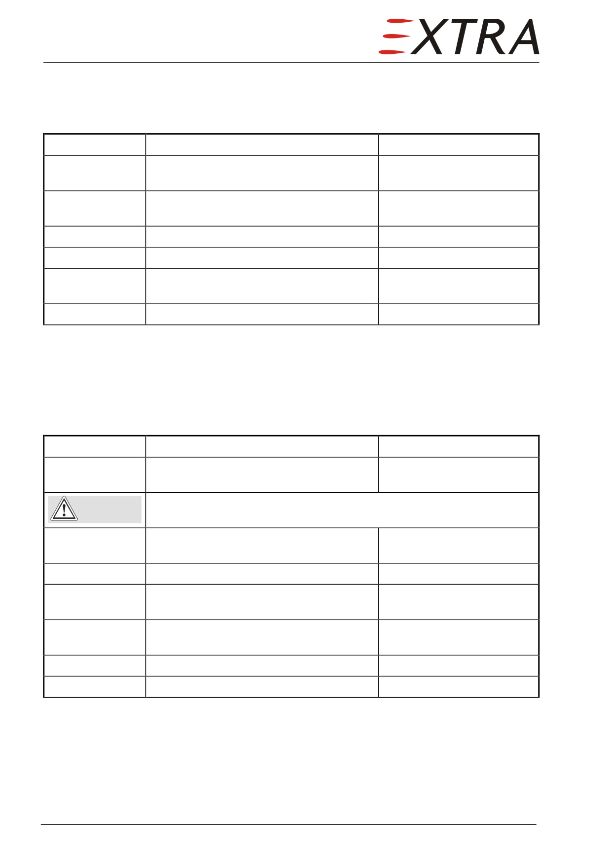
25-10-22
RH Side Armrest Paneling
Removal/Installation
Detail Steps/Work Items
Key Items
1
Ensure BATT switch is OFF and no external
power connected.
2
Remove microphone socket cover on rear
top of panel.
3
Remove screw at lower front panel side.
4
Remove screw at lower rear panel side.
5
Slightly lift panel and remove it against
flight direction.
6
Install in reverse sequence of removal.
25-10-23
Front Ceiling Paneling
Removal/Installation
Detail Steps/Work Items
Key Items
1
Ensure BATT switch is OFF and no external
power connected.
Take care not to damage sunblinds. Swivel sunblinds up before
CAUTION
removing ceiling panel
2
Remove 4 screws around upper windshield
frame.
3
Remove 4 screws near panel edges.
4
Disconnect plug for dome light/speaker
wiring.
5
Carefully remove adhesive tape at panel
back side.
6
Remove front ceiling paneling.
7
Install in reverse sequence of removal.
Page 8 25
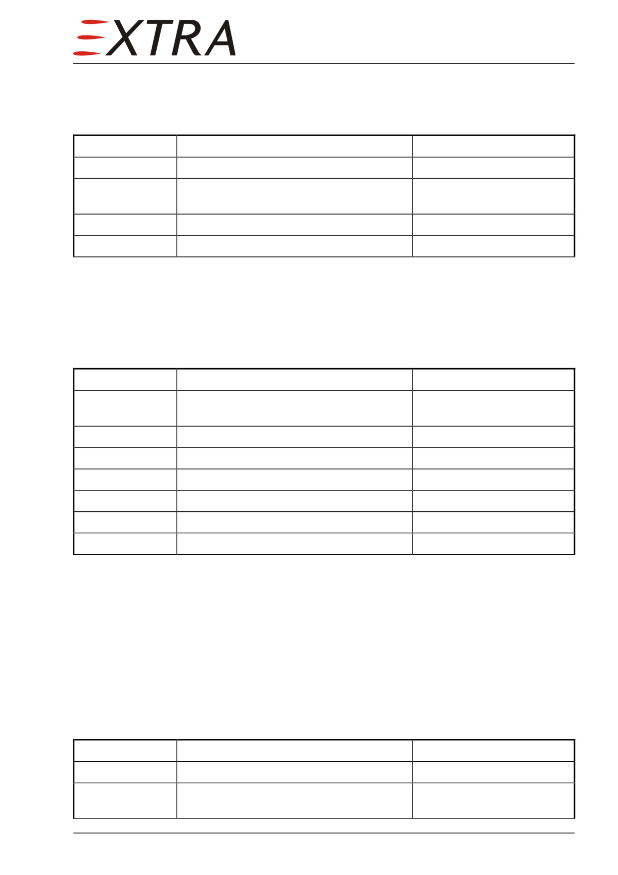
25-10-24
Upper Side Paneling LH/RH Side
Removal/Installation
Detail Steps/Work Items
Key Items
1
Remove 2 screws in windshield frame area.
2
Remove 2 screws in front cabin window
contour area.
3
Remove upper side paneling.
4
Install in reverse sequence of removal.
25-10-25
Windshield Middle Strut Paneling
Removal/Installation
Detail Steps/Work Items
Key Items
1
Ensure BATT switch is OFF and no external
power connected.
2
Remove 2 screws at compass.
3
Disconnect wiring for compass lighting.
4
Remove compass.
5
Remove 4 screws at paneling.
6
Remove windshield middle strut paneling.
7
Install in reverse sequence of removal.
25-10-26
Middle Console Paneling Upper Part
Description
The middle console paneling consists of an upper and lower part. The upper
part is screwed on the lower part and on the middle console structure.
Removal/Installation
Detail Steps/Work Items
Key Items
1
Remove trim wheel.
1 Phillips screw
2
Remove the back-up microphone from the
middle console.
25 Page 9
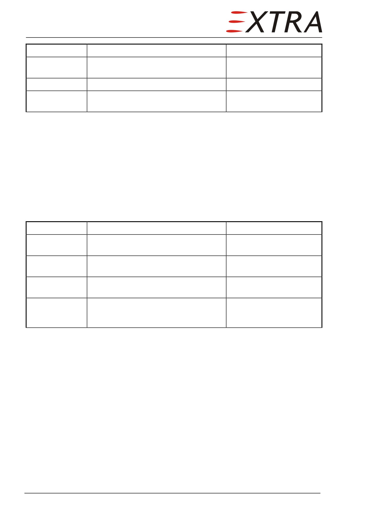
Detail Steps/Work Items
Key Items
3
Remove the upper part of middle console
24 Phillips screws
paneling.
4
Install in reverse sequence of removal.
5
Check the function of the back-up
microphone.
25-10-27
Middle Console Paneling Lower Part
Description
The lower part of the middle console paneling is aligned by 4 guiding pins in
the fuselage frame and fixed by the upper part of the paneling.
Removal/Installation
Detail Steps/Work Items
Key Items
1
Remove upper part of the middle console
Refer to Subject 25-12-06
paneling.
2
Disconnect air hoses from the legroom
1 worm drive hose clamp
dispensers.
each side
3
Move lower part paneling some centimeter
aft and remove.
4
Install in reverse sequence of removal.
Insert guide pins to the
related holes in the forward
paneling edges.
Page 10 25
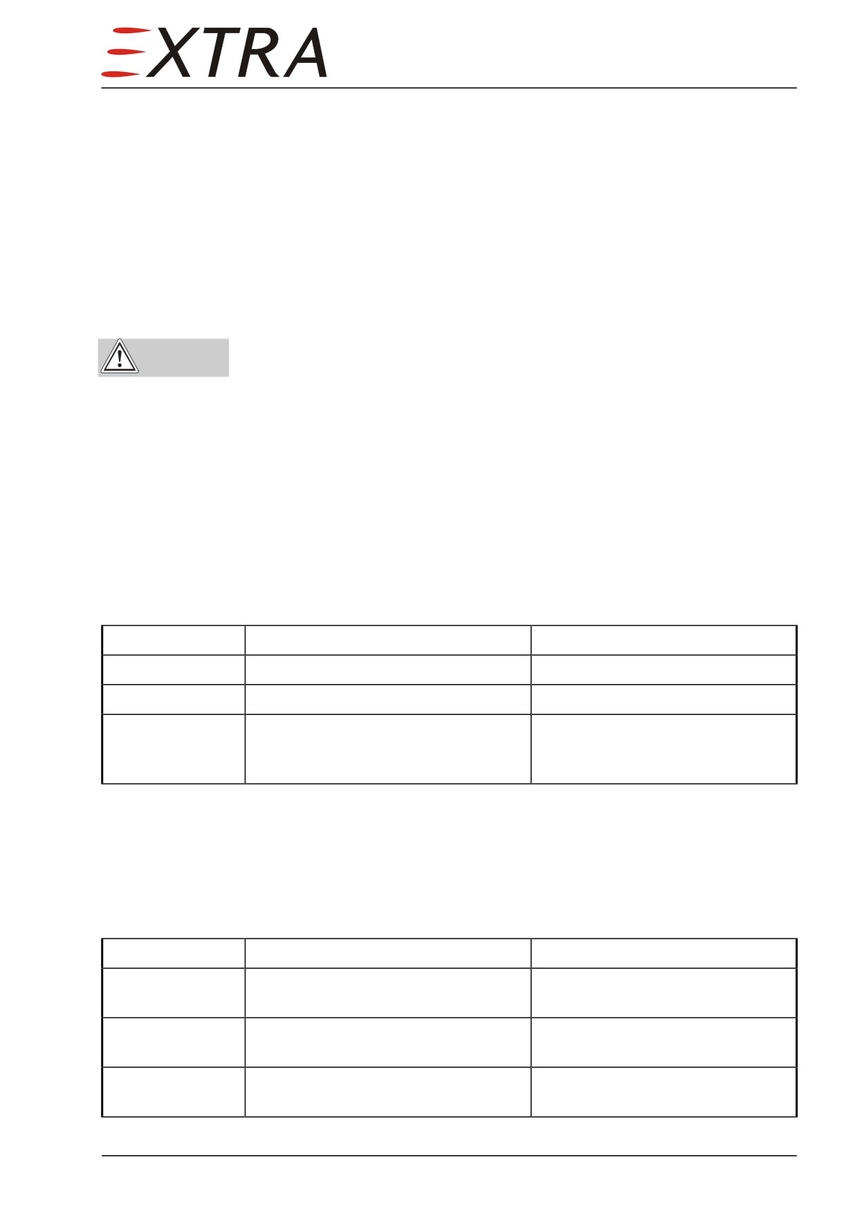
25-20-00
PASSENGER COMPARTMENT
25-20-10
Seats
The passenger seats are one piece seats as well but are placed on a fix position.
However the backrest of both aft seats can be swiveled forward allowing easy
access to the baggage compartment. For this purpose a release handle located
on the inner side of the backrest has to be pulled up.
Ensure backrest is locked by checking the down position of the release
WARNING handle before using the seat.
The seat belts provide a conventional adjustment however the locking
mechanism is placed on the inner side of the seat providing a lock for the
shoulder strap, which is equipped with inertia reels. The attachments of the seat
belts and shoulder harnesses are integrated in the seat.
25-20-11
Front Passenger Seats
Removal/Installation
Detail Steps/Work Items
Key Items
1
Remove screws at mounting console.
4 Allen screws LN 29952-0615M
2
Remove seat.
3
Install in reverse order of removal.
If necessary, use mounting template
at landing gear attachment for front
side screws.
25-20-12
Aft Passenger Seats
Removal
Detail Steps/Work Items
Key Items
1
Remove front paneling of baggage
To get access to the mounting
compartment from seat assembly.
consoles.
2
Remove back side screws at inner and
4 Allen screws LN 9037 - 06018
outer seat mounting console.
3
Remove front side screws at inner and
1 Allen screw LN 9037 - 06016 and
outer seat mounting console.
2 Allen screws LN 9037 - 06018
25 Page 11
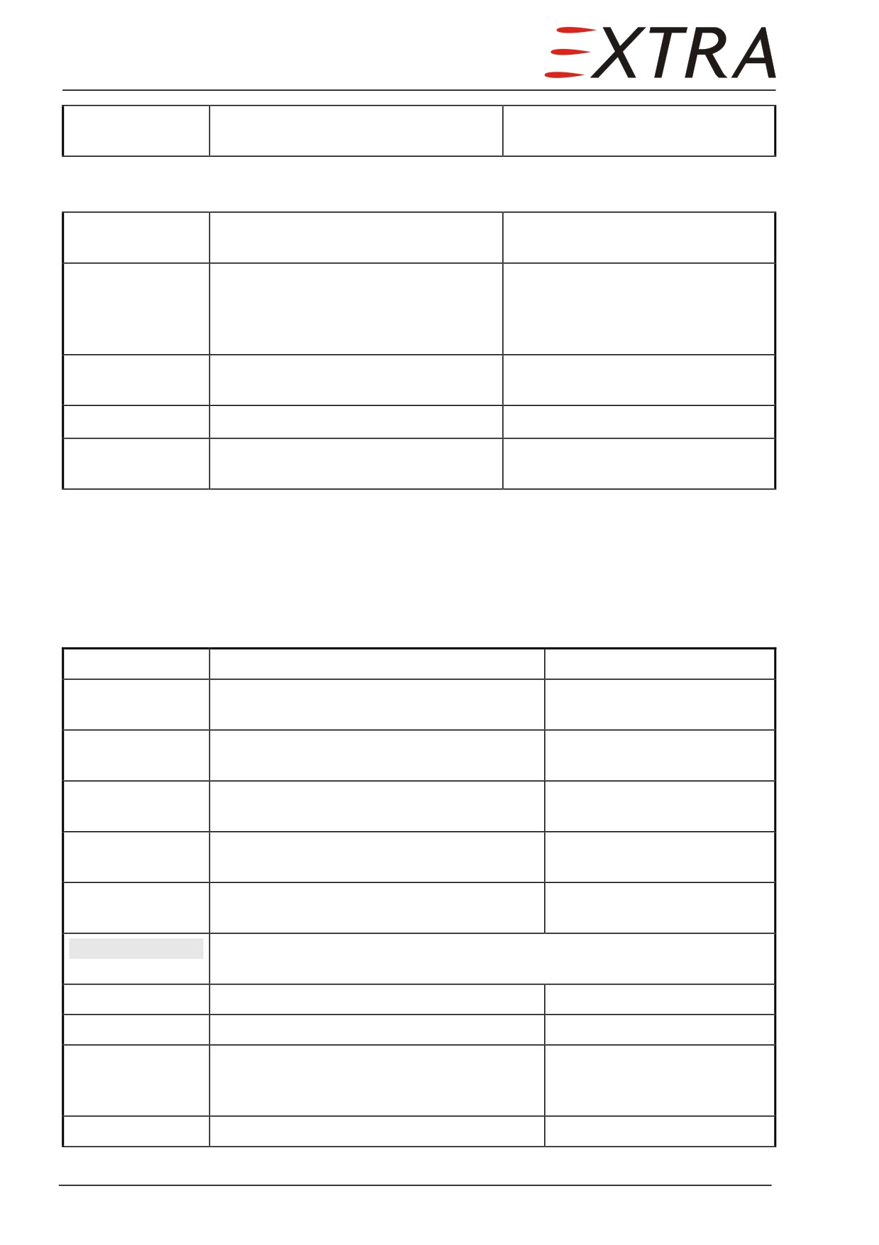
4
Remove screws at higher angle
6 Allen screws AN 5260 - 1032
bracket.
Installation
1
Insert front side screws at inner and
1 Allen screw LN 9037 - 06016 and
outer seat mounting console.
2 Allen screws LN 9037 - 06018
2
Before tightening front side screws
4 Allen screws LN 9037 - 06018
completely, adjust seat from rear side
and install back side screws at inner
and outer seat mounting console.
3
Tighten front side screws at inner and
outer seat mounting console.
4
Install screws at higher angle bracket.
6 Allen screws AN 5260 - 1032
5
Reinstall front paneling of baggage
compartment..
25-20-21
LH Side Armrest Paneling
Removal/Installation
Detail Steps/Work Items
Key Items
1
Ensure BATT switch is OFF and no external
power connected.
2
Remove microphone socket cover on front
top of panel.
3
Remove microphone socket cover on rear
top of panel.
4
Remove 5 screws at entrance bottom panel
sheet.
5
Loosen screws at door sealing frame in
armrest area.
NOTE
On some aircraft, the armrest is fixed with additional latches to the door
frame. In this case remove the screws and the latches completely.
6
Remove screw at lower front panel side.
7
Remove screw at lower rear panel side.
8
Pull armrest together with frame floor
finishing inboard and remove it against
flight direction.
9
Install in reverse sequence of removal.
Page 12 25
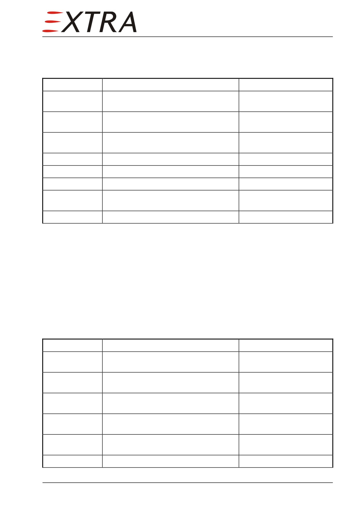
25-20-22
RH Side Armrest Paneling
Removal/Installation
Detail Steps/Work Items
Key Items
1
Ensure BATT switch is OFF and no external
power connected.
2
Remove microphone socket cover on front
top of panel.
3
Remove microphone socket cover on rear
top of panel.
4
Remove table.
Refer to Subject 0.
5
Remove screw at lower front panel side.
6
Pull back frame floor finishing.
7
Slightly lift panel and remove it against
flight direction.
8
Install in reverse sequence of removal.
25-20-31
Storage Boxes LH/RH
Description
Storage boxes are located between LH and RH side pilot’s/copilot’s and front
passenger seats. They provide a place for depositing especially the emergency
torch, first aid kit and the aircraft documentation material.
Removal/Installation
Detail Steps/Work Items
Key Items
1
Ensure BATT switch is OFF and no external
power connected.
2
Slide pilot’s and co-pilot’s seat into most
forward position.
3
Remove 2 screws at front and back bottom
side.
4 LH box
Remove screws at floor and back wall of
upper and lower storage compartments.
4 RH box
Take out fire extinguisher, remove bolts
holding extinguisher support bracket.
5
Install in reverse sequence of removal.
25 Page 13
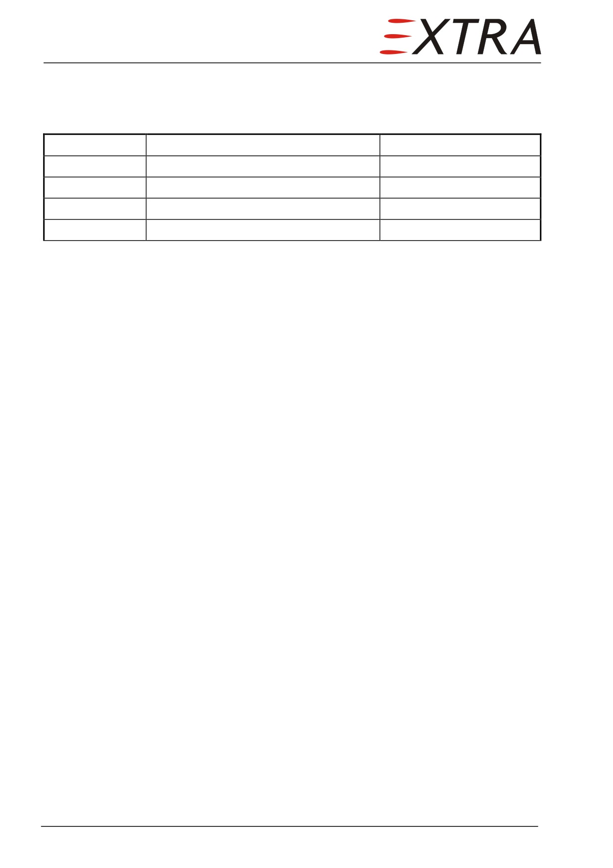
25-20-32
Table
Removal/Installation
Detail Steps/Work Items
Key Items
1
Remove 2 screws at table underside.
2
Remove 2 sheatings.
3
Remove table.
4
Install in reverse sequence of removal.
Page 14 25
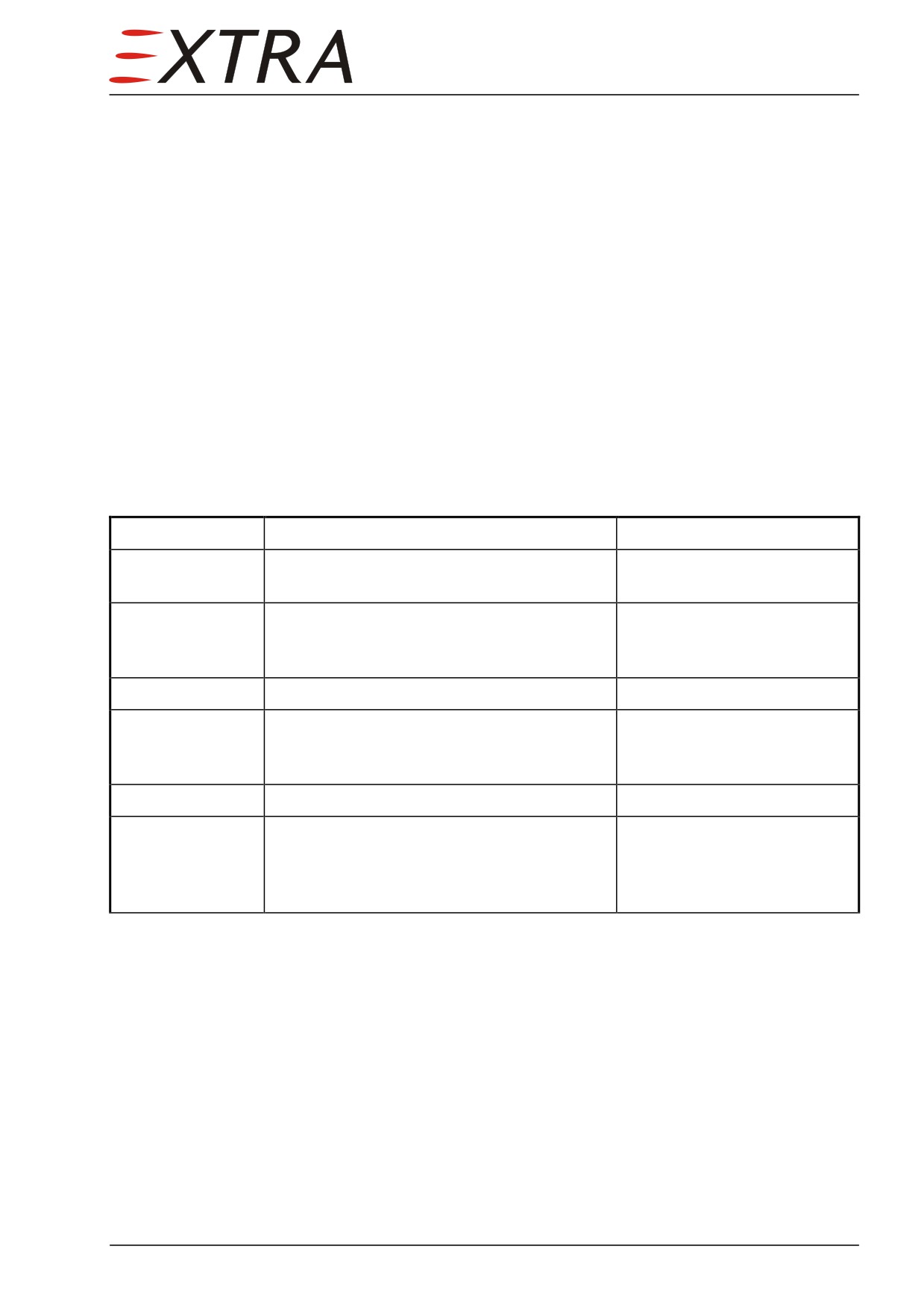
25-50-00
BAGGAGE COMPARTMENT
Description
The baggage compartment is located behind the aft passenger seats. To get
access the backrest of both aft seats can be swiveled forward. The release
handle is placed on the left side of the backrest.
The baggage can be secured by tie down belts, which are to be fastened on eyes
located on two compartment sides.
25-50-01
Tie Down Belts
Removal/Installation
Detail Steps/Work Items
Key Items
1
Release the handles at aft passenger seat
backrests and swivel backrests forward.
2
Remove 2 Phillips screws AN 526 C .1032
R8 securing front belt brackets to LH and
RH side console.
3
Remove front belt.
Remove 2 Phillips screws AN 526 C .1032
R8 securing aft belt brackets to LH and RH
side console.
Remove aft belt.
4
Install in reverse sequence of removal.
Install screws just so tight,
that belt brackets can be
rotated freely, but without
play.
25 Page 15
Chapter 27
Flight Controls
27 Page 1
TABLE OF CONTENTS
27-00-00
GENERAL
5
Description
5
27-00-01
Control Cable
5
Tensions
5
Figure 27-01
Control System Surview
6
27-00-10
CONTROL SPRINGS
7
Location
7
27-00-11
Down-Spring
7
Description
7
27-00-12
Interconnection Aileron/Rudder
7
Description
7
27-00-13
Centering Rudder
8
Description
8
27-00-14
Nose Gear Steering
8
Description
8
27-00-15
Nose Gear Control Cable
8
Description
8
27-10-00
AILERONS
9
Description
9
Troubleshooting
9
Removal/Installation
10
27-10-01
Aileron Cables
10
Removal/Installation
10
27-20-00
RUDDER
11
Description
11
Troubleshooting
11
Removal/Installation
12
27-20-01
Rudder Cables
12
Removal/Installation
12
27-30-00
ELEVATOR AND TAB
14
Description
14
Troubleshooting
14
Removal/Installation
16
27-30-01
Elevator Cables
16
Removal/Installation
16
Page 2 27
27-50-00
FLAP SYSTEM
18
Description
18
Rigging and Adjustment
18
Track Adjustment
19
Guidance Checks and Adjustment
19
Actuation Adjustment
20
27-50-01
Flap Drive Motor
21
Description
21
27-50-02
Inboard Power Transmission Flexible Shaft
22
Description
22
27-50-03
Outboard Power Transmission Flexible Shaft
22
Description
22
27-50-04
Power Transmission Screw Jacks
23
Description
23
27-50-05
Flap Control Box
23
Description
23
27-50-06
Flap Limit Switches
24
Description
24
Adjustment
24
27-50-07
Flap Asymmetry Senders
26
Adjustment
26
27 Page 3