Extra 500. Maintenance Manual (2012) - page 9
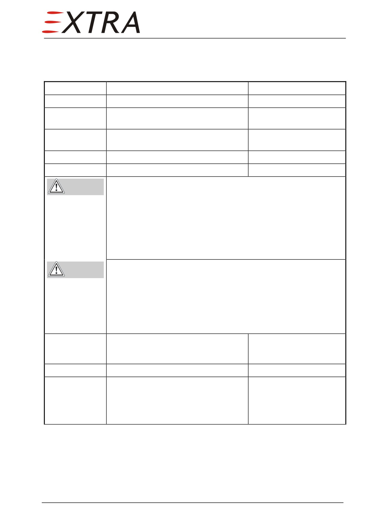
28-10-01
Tank
Sealant Repair
Detail Steps/Work Items
Key Items
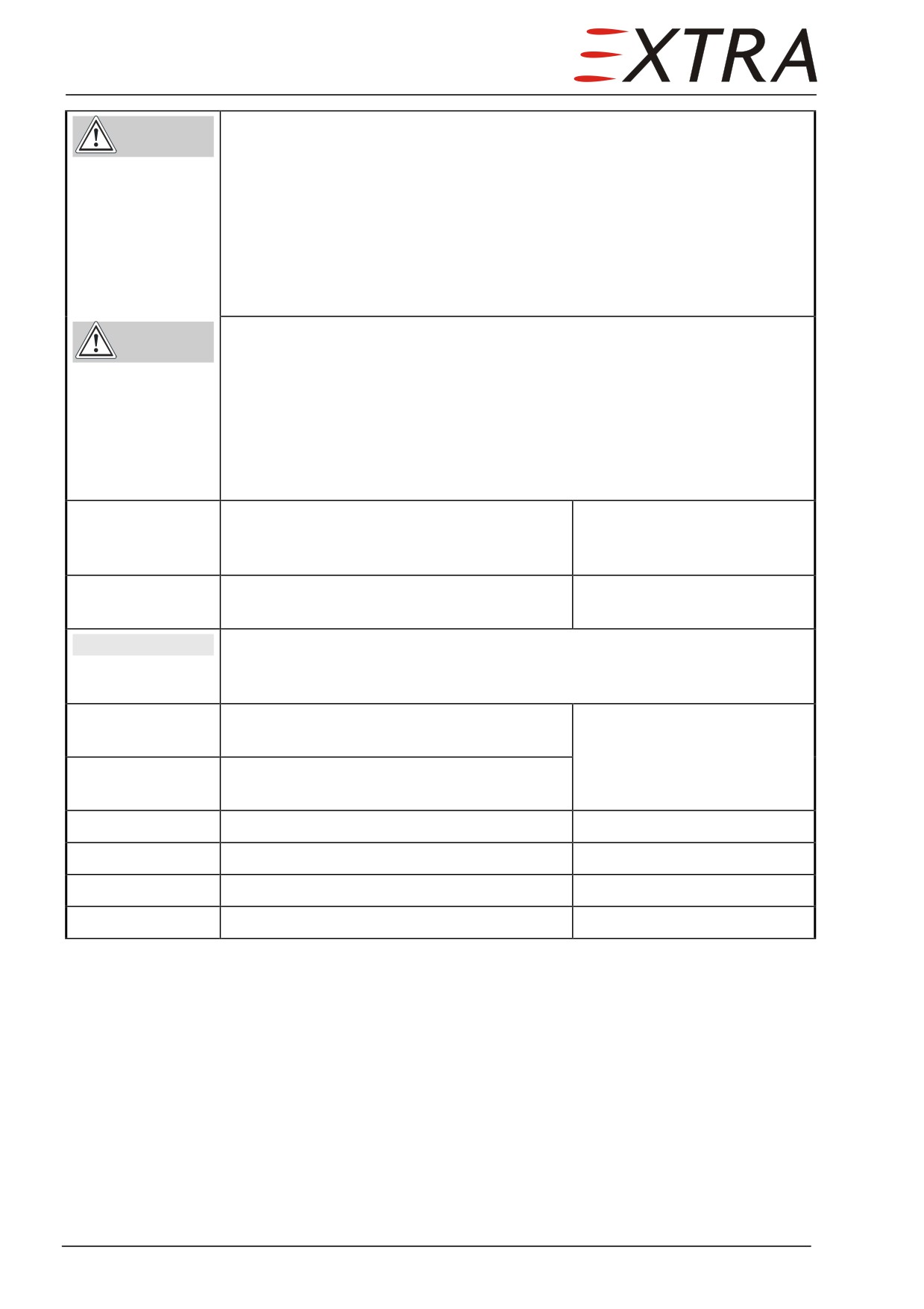
1
Drain the fuel system.
Refer to Chapter 12-10-02
2
Observe precautions concerning Reduction
Refer to Subject 28-00-00
of Fuel Tank Vapor Hazards.
3
Remove applicable fuel compartment access
Refer to Chapter 51-00-01
panels.
4
Clean area.
5
Sand the area to be repaired.
Only ruff it up
PR 1750 accelerator contains harmful vapors and is readily absorbed
WARNING
through the skin.
Avoid all contact with the skin and ingestion.
Always wash hands before eating or smoking.
Use adequate ventilation, hand protection and chemical-type goggles
when working with this product.
If accelerator contacts skin, flush area with warm water. Obtain medical
attention in cases of extreme exposure or ingestion.
PR 1750 sealant contains solvents.
WARNING
Use adequate ventilation or air-supplied respirators during application.
Avoid repeated or prolonged breathing of vapors.
In case of extreme vapor exposure, remove affected personnel to fresh
air immediately and obtain medical attention.
For complete health and safety information, refer to Le Joint Francais
material safety data sheet PR 1750 (LOAP 41).
6
Apply PR 1750 tank sealant.
For mixing and application of
PR 1750 sealant refer to
manufacturer's instructions.
7
Perform a fuel tank leakage test.
See Leakage Test below.
8
Wait for at least 3 hours before filling the
An absolute humidity of at
tank.
least 10g/m3 is needed for
curing. This corresponds with
35% relative humidity at
23°C and 78% at 10°C.
Draining
Refer to Chapter 12-10-02.
28 Page 11
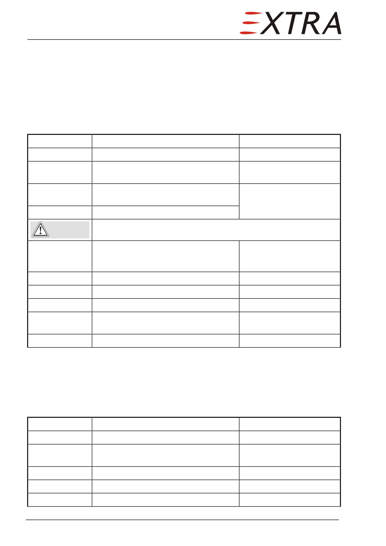
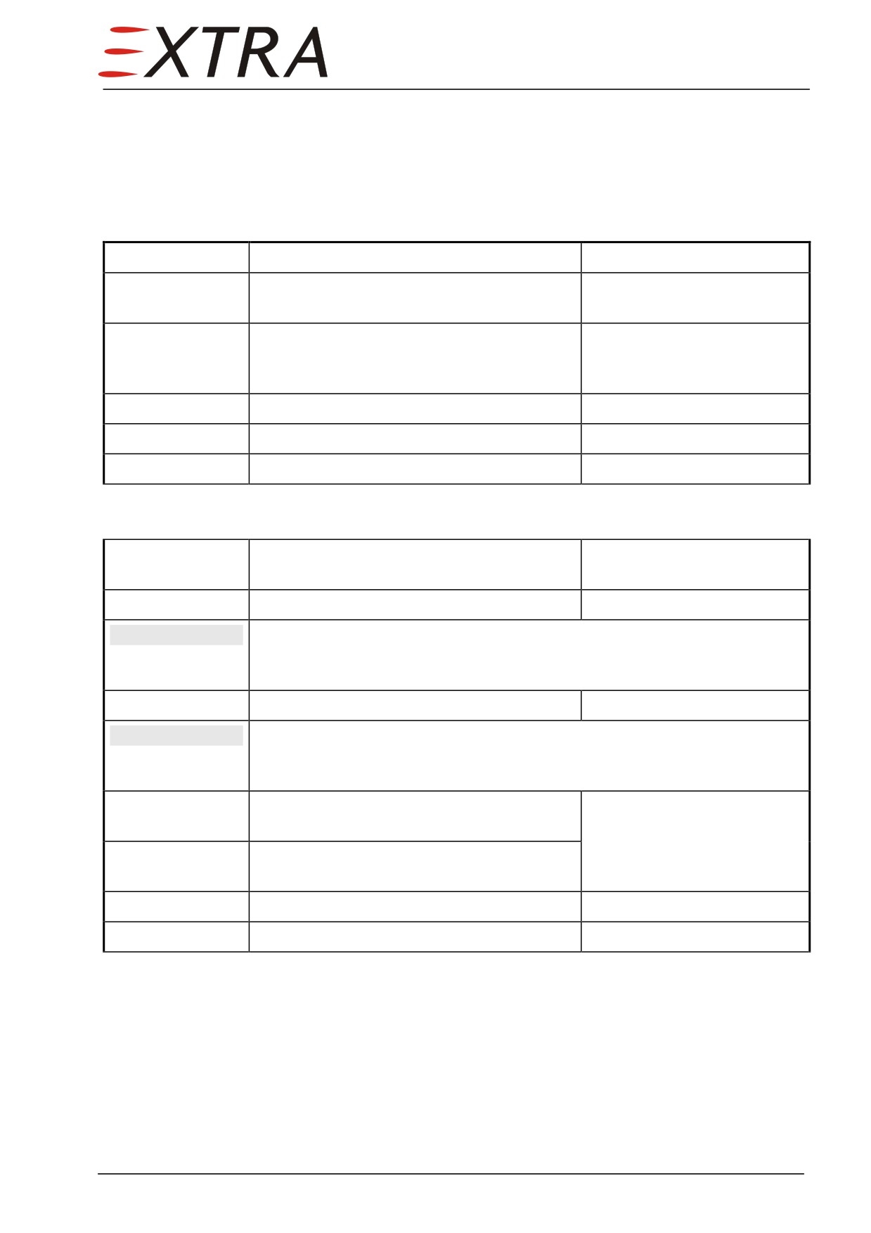
Leakage Test
After opening a fuel tank (except the avionic bay access panels) or a tank
repair, the tank shall undergo a leakage test. It is recommended to test all tanks
together or LH and RH individually. The LH and RH tanks are connected by
an interconnecting vent line, located in the avionic bay. It needs to be removed
and the fittings in the root ribs plugged if the LH or RH should be tested
individually. Furthermore, the four overpressure valves in the aft spar must be
plugged or held shut as they have a lower cracking pressure as the required test
pressure.
Detail Steps/Work Items
Key Items
1
Make sure aircraft is completely drained.
Refer to Chapter 12-10-02.
2
Observe precautions concerning Reduction
Refer to Subject 28-00-00
of Fuel Tank Vapor Hazards.
3
Remove interconnecting vent line between
If one tank shall be tested
LH and RH wing tank.
individually.
4
Plug the appropriate fitting.
Make sure the upper door is closed before extending flaps.
CAUTION
5
Extend flaps to 30°.
To gain access to the
overpressure valves from the
outside.
6
Plug or hold shut the overpressure valves.
7
Plug vent system.
8
Turn fuel selector valve to OFF-position.
9
Pressurize the tanks slowly to 120 mbar
Tanks pressure shall be
(1.74 psig).
steady for min. of 10 minutes.
10
Return aircraft to normal.
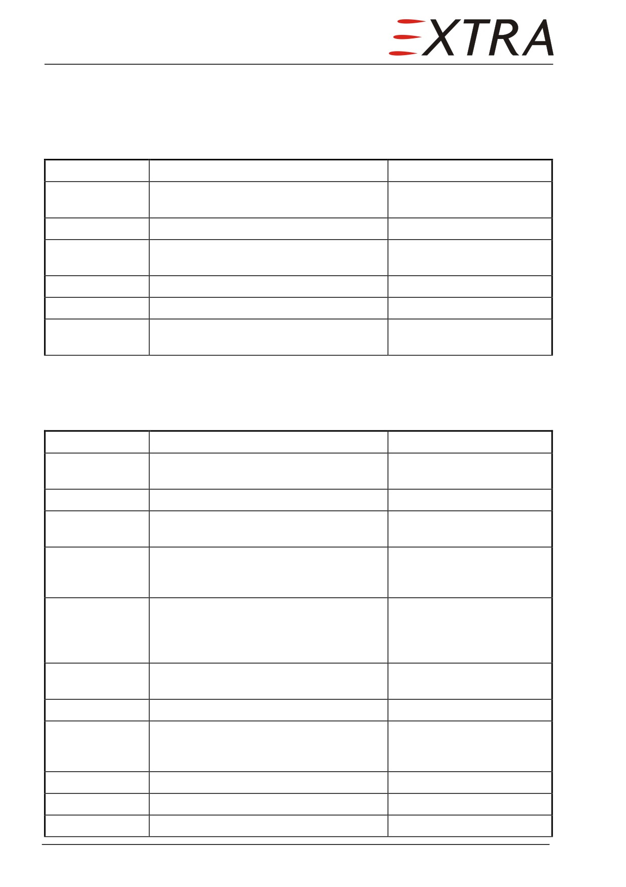
28-10-02
Drain (Curtis)
Removal/Installation
Detail Steps/Work Items
Key Items
1
Drain collector and main compartment.
Refer to Chapter 12-10-02
2
Observe precautions concerning Reduction
Refer to Subject 28-00-00
of Fuel Tank Vapor Hazards.
3
Remove fuel sump access panel.
Refer to Chapter 51-00-01
4
Carefully screw drain out of fitting.
5
Install in reverse sequence of removal.
Use Loctite 577
Page 12 28
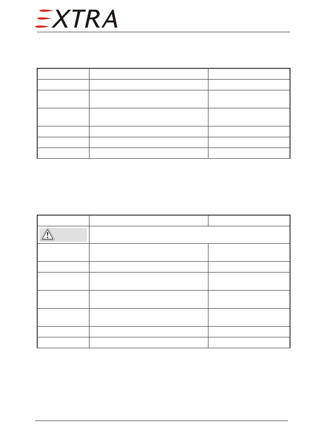
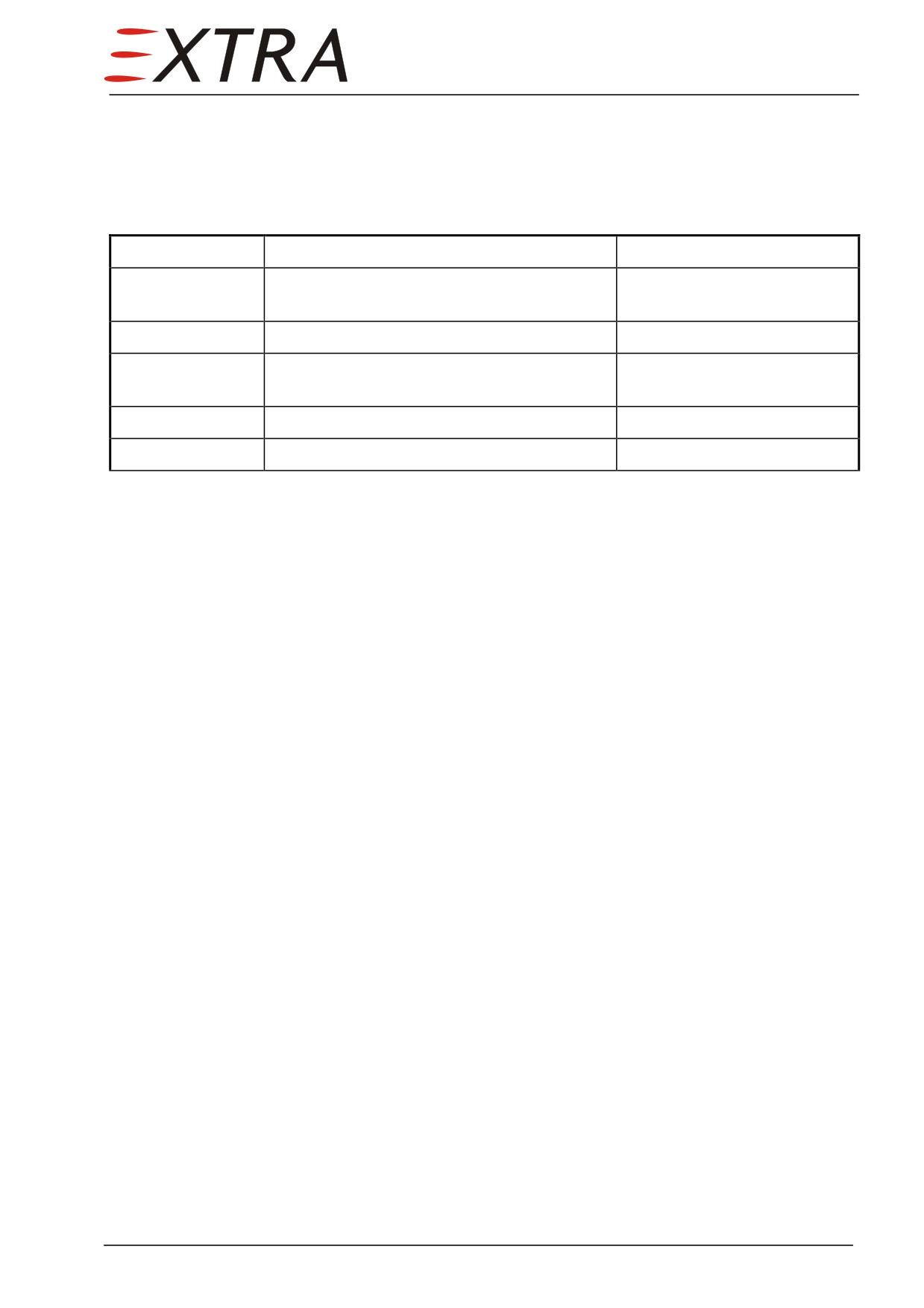
28-10-03
Flush Drain Valve
Removal/Installation
Detail Steps/Work Items
Key Items
1
Drain fuel system.
Refer to Chapter 12-10-02
2
Observe precautions concerning Reduction
Refer to Subject 28-00-00
of Fuel Tank Vapor Hazards.
3
Remove applicable fuel compartment access
Refer to Chapter 51-00-01
panels.
4
Loosen nut on tank inside.
5
Install vice versa.
Use Loctite 577
6
Perform tank leakage test.
Refer to Subject 28-10-01
28-10-04
Pressure Relief Valve
Removal/Installation
Detail Steps/Work Items
Key Items
Ensure cabin door is closed before extending wing flaps.
CAUTION
1
Place wing flaps to the 30° position.
Refer to EXTRA 500 Pilot’s
Operating Handbook
2
Drain fuel system.
Refer to Chapter 12-10-02
3
Observe precautions concerning Reduction
Refer to Subject 28-00-00
of Fuel Tank Vapor Hazards.
4
Remove applicable fuel compartment access
panel.
5
Screw out while holding plastic fitting from
inside of tank to keep it from turning.
6
Install vice versa.
Use Loctite 577
7
Perform tank leakage test.
Refer to Subject 28-10-01
28 Page 13
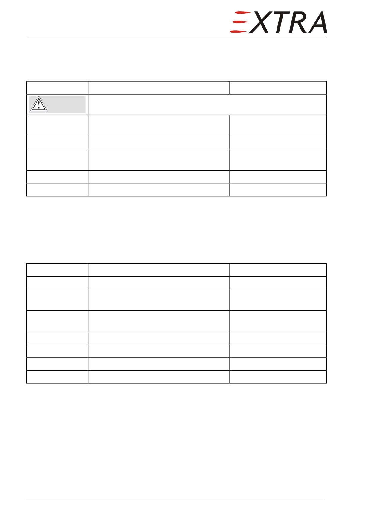
28-10-05
Pressure Relief Valve O-ring
Replacement
Detail Steps/Work Items
Key Items
Ensure cabin door is closed before extending wing flaps.
CAUTION
1
Place wing flaps to the 30° position.
Refer to EXTRA 500 Pilot’s
Operating Handbook
2
Drain related fuel compartment.
Refer to Chapter 12-10-02
3
Observe precautions concerning Reduction
Refer to Subject 28-00-00
of Fuel Tank Vapor Hazards.
4
Pull pressure relief valve poppet.
5
Replace O-ring
28-10-06
Float Valve
Removal/Installation
Detail Steps/Work Items
Key Items
1
Drain fuel system.
Refer to Chapter 12-10-02
2
Observe precautions concerning Reduction
Refer to Subject 28-00-00
of Fuel Tank Vapor Hazards.
3
Remove applicable fuel compartment access
Refer to Chapter 51-00-01
panels.
4
Disconnect vent line.
5
Remove vent float valve from mounting.
2 screws
6
Install in reverse sequence of removal.
7
Perform tank leakage test.
Refer to Subject 28-10-01
Page 14 28
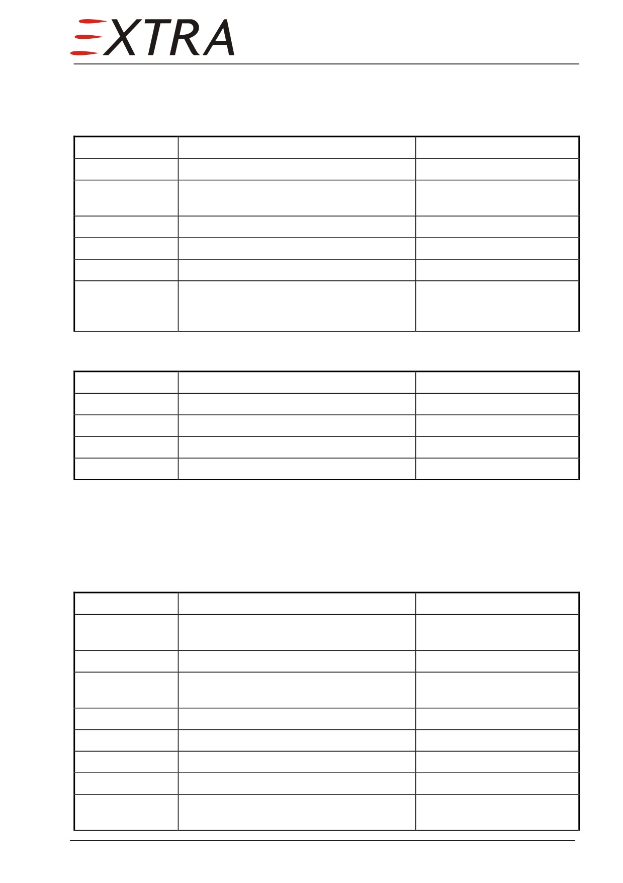
28-10-07
Fuel Transfer Filter
Removal/Installation
Detail Steps/Work Items
Key Items
1
Drain collector and main compartment.
Refer to Chapter 12-10-02
2
Observe precautions concerning Reduction
Refer to Subject 28-00-00
of Fuel Tank Vapor Hazards.
3
Open wing center fairing.
Refer to Chapter 51-00-01.
4
Disconnect fittings from filter.
5
Remove fuel transfer filter from aircraft.
Notice flow direction
8
Reinstall in reverse sequence of removal.
Make sure flow direction is
correct and bonding is
attached.
Cleaning
Detail Steps/Work Items
Key Items
1
Remove fuel transfer filter.
See above
2
Open filter.
3
Clean with Jet-A1.
4
Reinstall fuel transfer filter.
See above
28-10-08
Fuel Transfer Pump
Removal/Installation
Detail Steps/Work Items
Key Items
1
Ensure BATT switch is OFF and no external
power connected.
2
Drain collector and main compartment.
Refer to Chapter 12-10-02
3
Observe precautions concerning Reduction
Refer to Subject 28-00-00
of Fuel Tank Vapor Hazards
4
Open wing center fairing.
Refer to Chapter 51-00-01.
5
Disconnect electrical wiring.
6
Disconnect fuel hoses.
7
Remove fuel pump.
8
Install in reverse sequence of removal.
Make sure flow direction is
correct.
28 Page 15
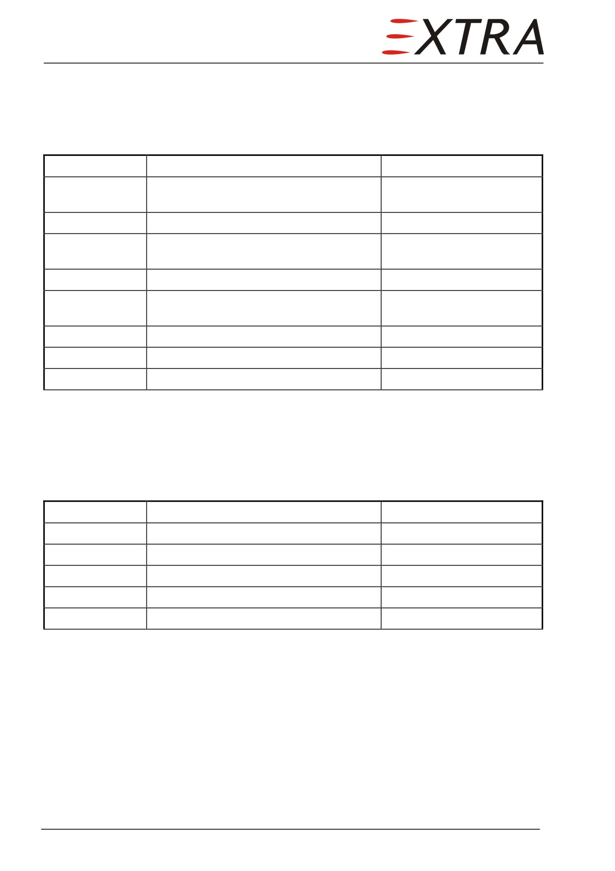
28-10-09
Jet Pump
The jet pumps incorporate a filter element (refer to Subject 28-10-10).
Removal/Installation
Detail Steps/Work Items
Key Items
1
Ensure BATT switch is OFF and no external
power connected.
2
Drain related fuel compartment.
Refer to Chapter 12-10-02
3
Observe precautions concerning Reduction
Refer to Subject 28-00-00
of Fuel Tank Vapor Hazards
4
Open related fuel compartment access panel.
Refer to Chapter 51-00-01.
5
Disconnect motive flow and transfer fuel
lines.
6
Remove jet pump
2 bolts
7
Install in reverse sequence of removal.
8
Perform tank leakage test.
Refer to Subject 28-10-01
28-10-10
Jet Pump Filter Element
Cleaning
Detail Steps/Work Items
Key Items
1
Remove jet pump.
Refer to Subject 28-10-09
2
Remove filter element.
Retaining ring
3
Clean with Jet-A1.
4
Reinstall filter element.
5
Reinstall jet pump.
Refer to Subject 28-10-09
Page 16 28
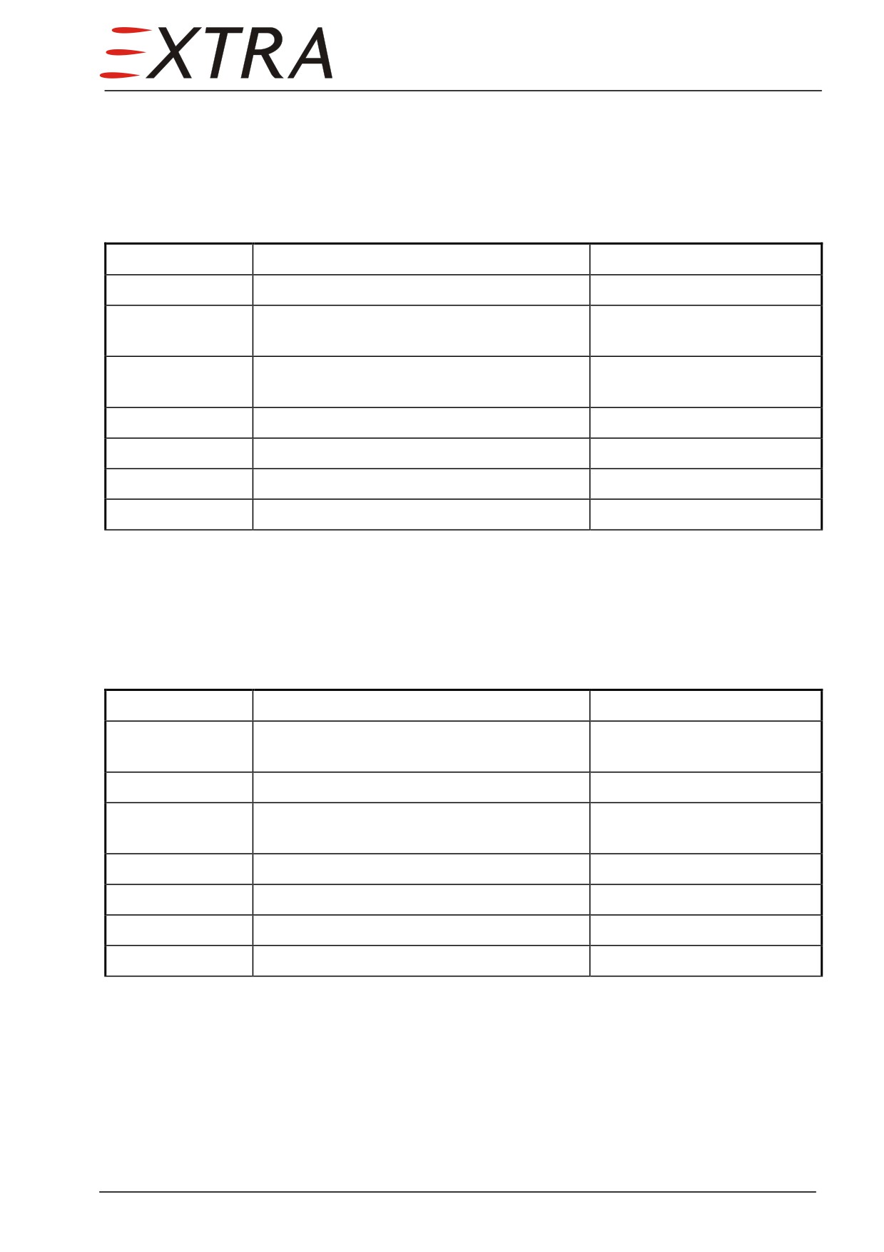
28-10-11
Rubber Hose
On the outflow side of the fuel transfer pumps rubber type hoses are installed
(SN 1002 and 1003 only).
Removal/Installation
Detail Steps/Work Items
Key Items
1
Drain fuel system.
Refer to Chapter 12-10-02
2
Observe precautions concerning Reduction
Refer to Subject 28-00-00
of Fuel Tank Vapor Hazards
3
Remove the applicable inner fuel
Refer to Chapter 51-00-01.
compartment access panel
4
Remove hose clamps from hose end.
5
Remove fuel hose.
6
Install in reverse sequence of removal.
7
Perform tank leakage test.
Refer to Subject 28-10-01
28-10-12
Pressure Switch
Removal/Installation
Detail Steps/Work Items
Key Items
1
Ensure BATT switch is OFF and no external
power connected.
2
Drain collector and main compartment.
Refer to Chapter 12-10-02
3
Observe precautions concerning Reduction
Refer to Subject 28-00-00
of Fuel Tank Vapor Hazards
4
Open avionic bay access panel.
Refer to Chapter 51-00-01.
5
Disconnect electrical connector.
6
Remove pressure switch.
7
Install in reverse sequence of removal.
28 Page 17
28-20-00
DISTRIBUTION
Description
Fuel runs from the LH and RH pick-up point at the bottom of the wing tank
collector compartments through fuel lines via check valves down to the fuel
selector valve.
The check valves prevent cross flow between the left and right tanks.
The fuel selector valve is located under the cockpit floor and direct
mechanically linked to the fuel selector handle between the pilot's and the
copilot's seat.
Just downstream the fuel selector valve an aluminum block is installed which
incorporates the fuel temperature sensor and a drain valve. This drain is the
lowest point of the fuel system and is accessible by a panel in the right
underside of the fuselage between the main and nose gear doors. The drain
provides a means to remove moisture and sediment from the fuel system.
Fuel lines are of aluminum tubing 5052-0 but in the engine compartment fire
resistant PTFE hoses are installed.
The hoses in the engine compartment are made fire resistant by means of red
silicone fiberglass sleeves or brown integrated fire sleeves. The hose
assemblies meet the requirements of MIL-DTL-27267 and MIL-DTL-25579 as
well as the fire-resistance requirements of AS1055. Fire-sleeves meet TSO
c53a requirements. The pick-up point fuselage connection fuel supply hoses
are conforming to MIL-H-5593.
From the firewall break-through the fuel is sucked though the aircraft fuel
filter. Aft of the filter, a manifold splits to the two parallel electrical fuel
pumps. Another manifold joins the fuel lines again though check valves. The
single line continues through the fuel flow transducer to the engine inlet.
For all maintenance work on the tanks, drain them completely. Be aware
WARNING
of fuel fumes and fuel stained cloth: highly inflammable!
Observe the safety notes given in Chapter 12-10-01, Refueling.
Power must be off, no external power connected, room well ventilated.
Page 18 28
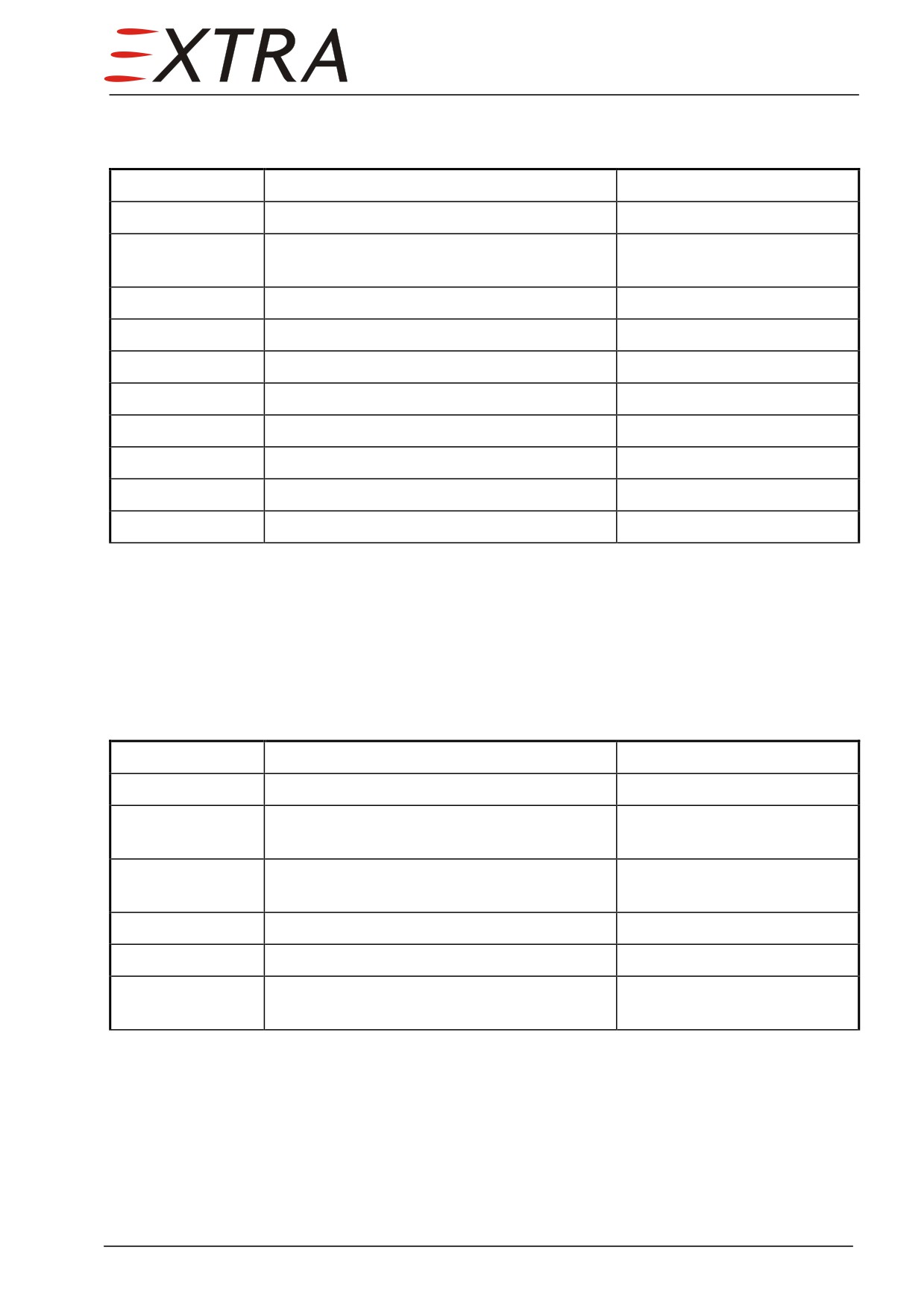
Bleeding Procedure
Detail Steps/Work Items
Key Items
1
Make sure tanks are not empty.
2
Disconnect fuel hose from engine and hold
in appropriate container.
3
Turn fuel selector valve to LEFT
4
Both fuel pumps ON
Until no more air bubbles
5
Both fuel pumps OFF
6
Turn fuel selector valve to RIGHT
7
Both fuel pumps ON
Until no more air bubbles
8
Both fuel pumps OFF
9
Reinstall fuel hose to the engine.
10
Turn fuel selector valve to BOTH
28-20-01
Check Valves (wing to selector valve)
Check valves are installed in front of the main gear bays.
Removal/Installation
Detail Steps/Work Items
Key Items
1
Drain fuel system.
Refer to Chapter 12-10-02
2
Observe precautions concerning Reduction
Refer to Subject 28-00-00
of Fuel Tank Vapor Hazards.
3
Remove LH/RH front fuselage access
Refer to Chapter 51-00-01.
panels.
4
Disconnect fuel hose.
5
Disconnect check valve from fitting.
6
Install in reverse sequence of removal.
Make sure flow direction is
correct.
28 Page 19
28-20-02
Check Valves (downstream electrical fuel pumps)
The check valves are installed in the fuel manifold on the aft engine fireshield.
Removal/Installation
Detail Steps/Work Items
Key Items
1
Set fuel selector valve to OFF.
2
Drain fuel at the lowest point drain and the
Refer to Chapter 12-10-02
fuel filter drain.
3
Remove both upper cowlings.
Refer to Ch. 71-10-01/02.
Fuel may be pressurized (30 psi max). Fuel may spill. Protect yourself
WARNING
and catch spilling fuel.
4
Disconnect fuel hose.
5
Remove lock wire.
6
Screw check valve out of manifold.
7
Install in reverse sequence of removal.
Make sure flow direction is
correct. Use new o-ring when
necessary (MS29512-08).
28-20-03
Fuel Selector Valve
The fuel selector valve is installed in the floor between the pilot and co-pilot
seat and in the compartment below.
Function Check
Detail Steps/Work Items
Key Items
1
Ensure both wing tanks contain fuel.
2
Place suitable container below the lowest
Refer to Chapter 12-10-03
point fuel drain.
3
Open fuel drain.
4
Select positions of fuel selector valve in the
following sequence and monitor fuel flow:
OFF: no fuel flow
LEFT: fuel flow
BOTH: fuel flow
If the behavior outlined left
RIGHT: fuel flow
applies, the fuel selector
OFF: no fuel flow
works correctly.
5
Check blocker between LH and RH OFF-
position.
6
Close the lowest point fuel drain.
Page 20 28
Page Date: 9. August 2013
Removal/Installation
Detail Steps/Work Items
Key Items
1
Drain fuel system completely.
Refer to Chapter 12-10-02
2
Remove forward keel beam access panel.
Refer to Chapter 51-00-01.
3
Disconnect the three fuel lines from the fuel
selector valve.
4
Remove the screws on the fuel selector
4 screws, in the cabin
handle.
5
Remove handle.
6
Unscrew the bolts on the bottom of the cup.
2 bolts
7
Remove the selector valve from the
structure.
8
Remove the spacer from selector valve.
2 screws
9
Install in reverse sequence of removal.
Selector valve can be
mounted in one way only
28-20-04
Fuel Filter Element
The fuel filter is installed in the engine compartment in front of the nose gear
bay.
Exchange
Detail Steps/Work Items
Key Items
1
Set fuel selector valve to OFF.
2
Drain fuel at the lowest point drain and the
Refer to Chapter 12-10-02
fuel filter drain.
3
Remove fuel filter access panel.
Refer to Chapter 51-00-01.
4
Remove lock wire and unscrew lower bowl
of fuel filter.
5
Replace filter element in bowl.
6
Screw bowl into filter.
torque 100-150 lbs-inch (11.3
- 16.9 Nm)
7
Lock wire.
8
Re-install fuel filter access panel.
Page Date:9. August 2013
28 Page 21
28-20-05
Electrical Fuel Pump
The electrical fuel pumps are installed in
the engine compartment on the
firewall, below the battery.
Removal/Installation
Detail Steps/Work Items
Key Items
1
Ensure BATT switch is OFF and no external
power connected.
2
Set fuel selector valve to OFF.
3
Drain fuel at the lowest point drain and the
Refer to Chapter 12-10-02
fuel filter drain.
4
Remove upper left cowling.
Refer to Chapter 71-10-01.
5
Disconnect electrical connection.
6
Disconnect fuel hoses.
7
Loosen worm-drive hose clamps.
(2)
8
Remove pump.
9
Install in reverse sequence of removal.
10
Perform Bleeding Procedure.
Refer to Subject 28-20-00
28-20-06
Rubber Hose
For connection of the wing tip pick-up to the fuselage a rubber type hoses are
installed.
Removal/Installation
Detail Steps/Work Items
Key Items
1
Ensure BATT switch is OFF and no external
power connected.
2
Remove respective fuel sump access panel
Refer to Chapter 51-00-01.
3
Disconnect copper braid bond from fuselage
Notice copper braid bond
side of hose connection.
position.
4
Disconnect fuselage side fitting.
5
Remove hose clamps and copper braid
bond.
6
Remove hose.
7
Install in reverse sequence of removal.
Ensure correct copper braid
bond position
Page 22 28
Page Date: 9. August 2013
28-40-00
INDICATION
Description
The fuel system indication system displays the following parameter:
• Left and right fuel quantity collector compartment
• Left and right fuel quantity main compartment
• Left and right fuel quantity auxiliary compartment
• Fuel flow
• Fuel pressure
• Fuel temperature
28-40-01
Fuel Quantity Sensor (collector compartment)
The fuel quantity probe is installed in the collector compartment on the root
rib.
Removal
Detail Steps/Work Items
Key Items
1
Ensure BATT switch is OFF and no external
power connected.
2
Open avionic bay access panels.
Refer to Chapter 51-00-01
3
Disconnect electrical connector from sensor.
4
Remove root rib inspection door.
14 bolts
5
Remove sensor from inspection door.
Installation
1
Ensure BATT switch is OFF and no external
power connected.
2
Clean root rib inspection door and sensor
surfaces with solvents to remove dirt and
grease.
28 Page 23
PR 1750 accelerator contains harmful vapors and is readily absorbed
WARNING
through the skin.
Avoid all contact with the skin and ingestion.
Always wash hands before eating or smoking.
Use adequate ventilation, hand protection and chemical-type goggles
when working with this product.
If accelerator contacts skin, flush area with warm water. Obtain medical
attention in cases of extreme exposure or ingestion.
PR 1750 sealant contains solvents.
WARNING
Use adequate ventilation or air-supplied respirators during application.
Avoid repeated or prolonged breathing of vapors.
In case of extreme vapor exposure, remove affected personnel to fresh
air immediately and obtain medical attention.
For complete health and safety information, refer to Le Joint Francais
material safety data sheet PR 1750 (LOAP 41).
3
Install sensor on root rib inspection door
For mixing and application of
with PR 1750 tank sealant.
PR 1750 sealant refer to
manufacturer's instructions.
4
Check the float points in the direction of
flight.
NOTE
If the hatch seal has become partly clear instead of white, slightly pull
those patches apart. Clear patches are NOT a sign that the seal is
defective!
5
Install root rib inspection door, torque bolts
3-5 Nm (26-44inch-lbs).
6
After at least one half hour re-torque the
bolts.
7
Connect electrical connector.
8
Make a tank leakage test.
Refer to Subject 28-10-01
9
Close avionic bay access panels.
Refer to Chapter 51-00-01
10
Recalibrate quantity indicator.
Page 24 28
28-40-02
Fuel Quantity Sensor (main or auxiliary compartment)
The fuel quantity sensor is installed on the inner tank inspection door of the
appropriate tank.
Removal
Detail Steps/Work Items
Key Items
1
Ensure BATT switch is OFF and no external
power connected.
2
Open appropriate tank access panel.
Sensor is on the inner tank
inspection door of the
corresponding compartment.
3
Remove inspection door.
4
Remove sensor from inspection door.
5 bolts
5
Disconnect electrical connector from sensor.
Installation
1
Ensure BATT switch is OFF and no external
power connected.
2
Connect electrical connector.
NOTE
When attaching sensor to hatch observe correct direction.
For main compartment: Make sure the float is pointing inboard
For auxiliary compartment: Make sure the float is pointing outboard
3
Attach sensor to inspection door.
NOTE
If the hatch seal has become partly clear instead of white, slightly pull
those patches apart. Clear patches are NOT a sign that the seal is
defective!
4
Install inspection door, torque bolts 3-5 Nm
(26-44 inch-lbs).
5
After at least one half hour re-torque the
bolts.
6
Recalibrate quantity indicator.
7
Reinstall appropriate tank access panel.
28 Page 25
28-40-03
Fuel Quantity Gauge
The fuel quantity gauges are installed in the RH instrument panel.
Removal/Installation
Detail Steps/Work Items
Key Items
1
Ensure BATT switch is OFF and no external
power connected.
2
Remove RH IFD.
Refer to Chapter 31-60-01.
3
Disconnect electrical connector from fuel
quantity gauge.
4
Unscrew attachment .
4 screws
5
Install in reverse order of removal.
6
If more than one gauge is replaced, check if
indicator shows proper tank.
Calibration
The calibration potentiometers are installed on PCB installed behind the LH
IFD.
Detail Steps/Work Items
Key Items
1
Ensure BATT switch is OFF and no external
power connected.
2
Remove RH IFD.
Refer to Chapter 31-60-01.
3
Disconnect electrical connector from fuel
quantity gauge.
4
Make sure the fuel quantity sensor is
installed and laying on the bottom of the
compartment (compartment is empty).
5
Measure with a calibrated, digital ohmmeter
For collector and main comp:
the resistance between pins 5 and 8.
The value must be 50.0 Ohm
For auxiliary compartment:
The value must be 80.0 Ohm
6
If value is not correct, follow the steps
below.
7a
Remove LH IFD.
Refer to Chapter 31-60-01.
7b
Use the potentiometer on the PCB behind
the RH IFD to bring the resistance value to
the required value.
7c
Reinstall the LH IFD.
8
Connect electrical connector.
9
Re-install the RH IFD.
Page 26 28
28-40-04
Fuel Flow Indicator
The fuel flow indicator is installed in the RH instrument panel.
Removal/Installation
Detail Steps/Work Items
Key Items
1
Ensure BATT switch is OFF and no external
power connected.
2
Remove RH IFD.
Refer to Chapter 31-60-01.
3
Disconnect electrical connector from fuel
flow indicator.
4
Unscrew attachment.
4 screws
5
Install in reverse sequence of removal.
K-Factor Setting
Refer to Shadin Avionics Miniflo-L Operating Manual (LOAP 42).
28-40-05
Pressure Transducer
For description and maintenance practices refer to Chapter 73-30-01.
28-40-06
Pressure Gauge
The fuel pressure gauge is integrated in the Digital Instrument Package (refer
to Chapter 77-40-02).
28 Page 27
Chapter 29
Hydraulic Power
29 Page 1
29-00-00
GENERAL
The hydraulic system of the EXTRA 500 is used to operate the landing gear
exclusively. Therefore all information concerning hydraulics is incorporated in
Chapter 32-30 Extension and Retraction.
29 Page 3
Chapter 30
Ice and Rain Protection
30 Page 1
TABLE OF CONTENTS
30-00-00
GENERAL
5
Description.......................................................................................................... 5
Removal/Installation/Repair
............................................................................... 5
Figure 30-1
De-Icing System Shematic
.................................................................................. 6
Troubleshooting
.................................................................................................. 7
30-10-00
AIRFOIL
10
Description
10
30-10-01
Pressure Regulator
10
Pressure Regulator Setting and Pressure Switch Check
10
Figure 30-2
Pressure Manifold
11
Figure 30-3
Pressure Regulator
12
Removal/Installation
12
30-10-02
Ejector Valve
13
Removal/Installation
13
30-10-03
Boots Timer
13
Removal/Installation
13
30-10-04
Pressure Switch
13
Removal/Installation
13
30-20-00
AIR INTAKES
15
Description
15
30-20-01
Bowden Cable
15
Removal/Installation
15
Rigging
16
30-20-02
Micro Switch
17
Removal/Installation
17
Rigging
17
30-20-03
Helical Metallic Hoses
17
Removal/Installation
17
30-30-00
PITOT, STATIC AND STALL WARNING
18
Description
18
30-30-01
Current Sensor (Avionic Bay)
18
Removal/Installation
19
30-30-02
Current Sensor (Tail Cone)
19
Removal/Installation
19
30-40-00
WINDSHIELD
20
30-40-01
Windshield Heat Controller
20
Removal/Installation
20
Page 2 30
Page Date: 9. August 2013
30-40-02
Windshield Heat Current Sensor
21
Removal/Installation
.........................................................................................21
30-60-00
PROPELLER
..................................................................................................22
Description
........................................................................................................22
30-60-01
Propeller Ammeter..........................................................................................22
Removal/Installation
.........................................................................................22
30-70-00
WATER LINES
...............................................................................................23
30-80-00
DETECTION
...................................................................................................24
30-80-01
Ice Light
...........................................................................................................24
Removal/Installation
.........................................................................................24
Page Date:
30 Page 3
30-00-00
GENERAL
Description
The following icing protection systems are standard equipment on the
EXTRA 500 (refer to Figure 30-1):
1 Pneumatic de-ice boots for wing and empennage
2 Heated Pitot tubes and heated static ports
3 Heated stall warning sensor
4 Heated windshield
5 Heated engine inlet
6 Heated propeller blades
Removal/Installation/Repair
For respective information see manufacturers BF Goodrich publications
concerning “Estane De-Icers” as listed in the LOAP 18-22.
30 Page 5
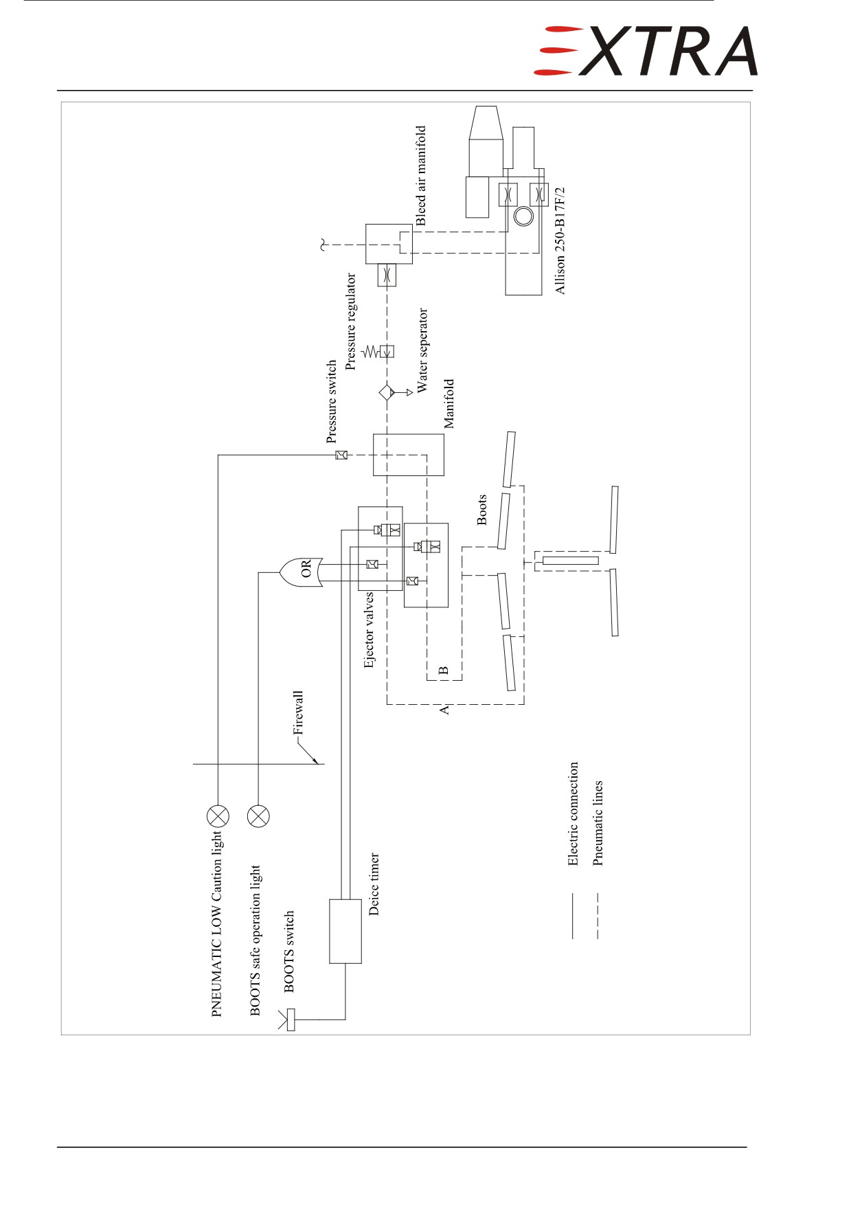
Figure 30-1
De-Icing System Shematic
Page 6 30
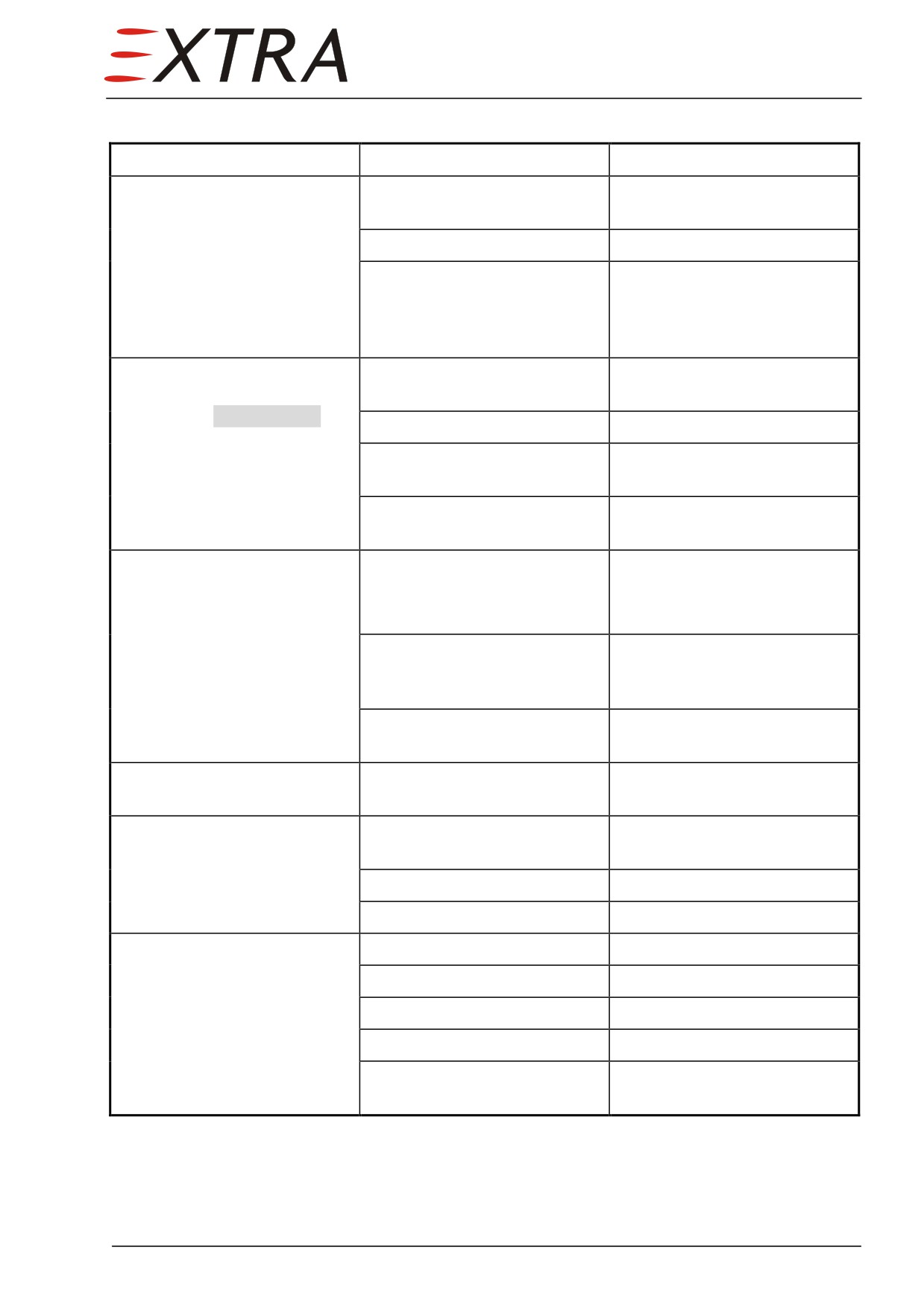
Troubleshooting
Complaint
Possible Cause
Remedy
Deice boots fail to inflate
Leakage in pressure system
Identify leak, seal or replace
completely
upstream ejector valves
defective part
Electric failure
Check wiring
Failure of:
Identify defective
timer, pressure regulating
component(s) and replace
valve, ejector valves, pressure
manifold
De-ice boots inflate only
Leakage in pressure lines
Identify leak, seal or replace
partially (low inflation
defective part
pressure, no DEICE BOOTS
Kinked pressure tube
Replace defective tube
safe operation light)
Failure of pressure regulating
Replace valve
valve
Electric failure
Check pressure sensors, wiring
and indication light
One of the two inflation
Failure of:
Identify defective component
sections (inner wing, outer
and replace
Timer, ejector valve, electric
wing and tail surfaces) fails to
wiring
inflate
Leakage of pressure lines
Check for leaks in pressure
downstream ejector valve
lines and boots, repair or
replace defective parts
Blockage downstream
Check for kinks in tubing,
distributing valve
replace
Time intervals out of
Failure of timer (or false
Replace timer
tolerances
timer)
Boot evacuation fails
Timer, ejector valve, or switch
Identify and replace or repair
failure
Electric failure
Check and repair wiring
Boot or line leakage
Identify and replace or repair
Inlet heating defect
Bowden cable broken
Replace
Bowden cable loose
Rig Bowden cable
Exhaust ‘ashtray’ broken
Replace
Exhaust is leaking
Replace
Exhaust helical metallic hose
replace
disconnected or leaking
30 Page 7
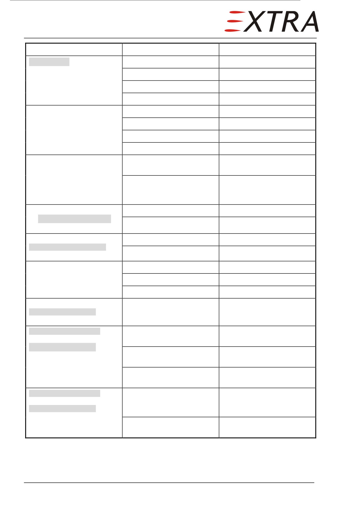
Complaint
Possible Cause
Remedy
INTAKE HEAT safe operation
Wiring defective
Replace
light does not illuminate on
Microswitch defective
Replace
activation
Bowden cable mis-rigged
Rig Bowden cable
Microswitch mis-aligned
Rig microswitch
Engine inlet anti ice system
Wiring defective
Replace
does not activate
Microswitch defective
Replace
Bowden cable mis-rigged
Rig Bowden cable
Microswitch mis-aligned
Rig microswitch
Water in boots system
Water separator drain line
Remove drain line blockage
blocked
Orifice in water separator
Remove blockage from and
blocked
clean (inside of) water
separator.
Pitot tube does not heat,
Wiring defective
Check and repair wiring
no PITOT HEAT LEFT/RIGHT
Pitot tube heat defective
Replace Pitot tube
indication
Static port does not heat
Wiring defective
Check and repair wiring
STATIC HEAT LEFT/RIGHT
Static port heat defective
Replace static port
indication
Lift detector (3 heating
Wiring defective
Check and repair wiring
circuits) does not heat
Current sensor defective
Replace current sensor.
Lift detector heat defective
Replace lift detector
Windshield heat inactive, no
High ambient temperature
Normal system function
WINDSHIELD HEAT ON
(windshield above 40°C)
indication
WINDSHIELD HEAT FAIL
Wiring to one temperature
Check and repair
active,
sensor in windshield defective
WINDSHIELD HEAT ON still
One windshield temperature
Replace windshield
active
sensor defective
Respective circuit in
Replace controller
controller defective
WINDSHIELD HEAT FAIL
Wiring to or both temperature
Check and repair
active,
sensors in windshield
WINDSHIELD HEAT ON
defective
inactive
Windshield controller
Replace controller
defective
Page 8 30
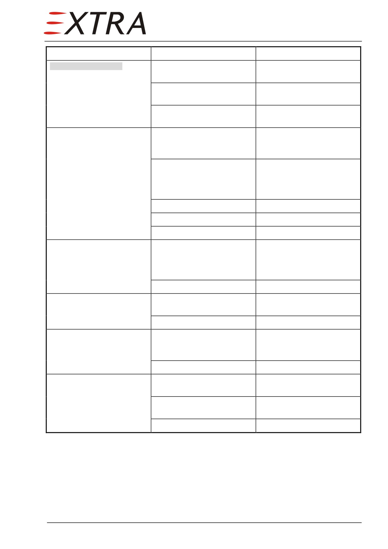
Complaint
Possible Cause
Remedy
WINDSHIELD HEAT ON
Wiring to heated area
Check and repair
inactive
defective
Heated area in windshield
Replace windshield
defective
Windshield controller
Replace controller
defective
Prop Ammeter shows zero
No power from aircraft to
Check wiring, circuit breaker
brushes
and switch, repair or replace
defective part
Open circuit brushes to heater
Repair wiring (check when
boots
stretching and flexing the
leads) or replace propeller in
case of heater element failure
Ammeter shunt defective
Replace shunt
Ammeter wiring defective
Repair wiring
Ammeter defective
Replace ammeter
Prop Ammeter shows low
Open circuit (or high
Identify whether wiring or
current (below green arc)
resistance) to at least one of
heater element itself is
the blade heating elements
defective. Repair wiring or
replace propeller
Ammeter defective
Replace ammeter
Ammeter shows excess
Power lead shorted to ground
Check insulation and replace
current (above green arc)
defective lead
Ammeter defective
Replace ammeter
Radio noise
Brushes arcing
Check for brush alignment,
dirty or rough slip rings and
slip ring alignment
Loose connection
Check wiring connections
Rapid brush wear and frequent
Brush assembly out of
Check and adjust brush
breakage
alignment
alignment
Slip ring wobbles
Check slip ring alignment,
replace slip ring
Rough slip rings
Replace (or refinish) slip ring
30 Page 9
30-10-00
AIRFOIL
Description
The leading edges of the airfoils (wing, horizontal and vertical stabilizer) are
protected against icing by inflatable rubber boots. The pressurized air for boot
inflation is supplied by engine bleed air. Nominal inflation pressure of the
system is 18 psig (1.25 bar). A system surview is given in Figure 30-1.
The system, when activated, inflates two leading edge boots groups in
sequence for ice shedding. Boot cycle A incorporates the inner wing boots,
cycle B the outer wing and empennage. When not inflated, suction will keep
the boots on the wing and empennage surfaces. The switching from under-
pressure to pressure is done by an ejector valve (one for each group), which is
commanded by the boots timer. The boots timer is activated with the BOOTS
switch on the left side panel.
30-10-01
Pressure Regulator
The pressure regulator is located in the engine compartment, on the LH upper
engine mount tube.
Pressure Regulator Setting and Pressure Switch Setting Check
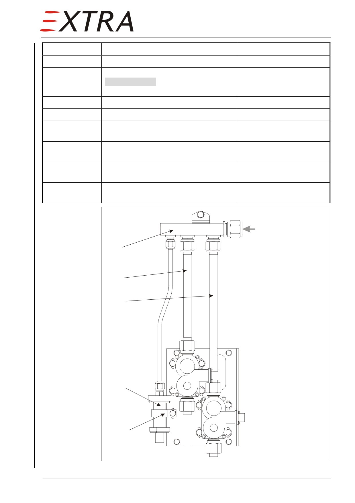
Refer to Figure 30-2 and Figure 30-3.
Detail Steps/Work Items
Key Items
1
Remove LH upper cowling.
Refer to Chapter 71-10-01.
2
Remove tubes (2 + 3, Figure 30-2) from
pressure manifold.
3
Plug one open fitting of the pressure
manifold.
4
Install a pressure indicator with an
indication range from minimum 0 thru
25 psig on the other fitting.
5
Disconnect the tube (3, Figure 30-3) from
the pressure regulator.
6
Connect 40 psig regulated shop air to the
open pressure regulator fitting.
7
Check pressure indication 19 psig.
tolerance: +/- 1 psig.
If reading out of tolerance:
a
Loosen counter nut (7, Figure 30-3).
b
Adjust pressure using the Allen set screw (8,
Figure 30-3).
Page 10 30
Page Date: 9. August 2013
Detail Steps/Work Items
Key Items
c
Fasten counter nut (7, Figure 30-3).
8
Slowly reduce shop air pressure and check
tolerance: +/- 0.5 psig.
PNEUMATIC LOW illuminates when pressure
drops below 15 psig.
If reading out of tolerance:
a
Replace pressure switch.
Refer to Section 30-10-04
9
Remove regulated shop air from pressure
regulator inlet fitting.
10
Connect the tube (3, Figure 30-3) to the
pressure regulator.
11
Remove pressure indicator and plug from
pressure manifold.
12
Reinstall tubes (2 + 3, Figure 30-2) to
pressure manifold.
from pressure regulator
1
Firewall
2
3
4
Legend:
1
pressure manifold
2
tube
5
3
tube
4
pressure switch
5
hose clamp
Figure 30-2
Pressure Manifold
Page Date:9. August 2013
30 Page 11
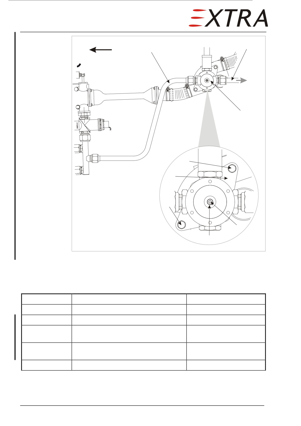
fwd
2
3
to
pressure
manifold
1
4
5
Legend:
1
pressure regulator
2
tube
6
3
tube
4
bolt
5
mounting plate
6
bolt
8
7
counter nut
8
Allen set screw
7
Figure 30-3
Pressure Regulator
Removal/Installation
Refer to Figure 30-3.
Detail Steps/Work Items
Key Items
1
Remove LH upper cowling.
Refer to Chapter 71-10-01.
2
Disconnect pneumatic lines (2 + 3).
3
Remove mounting plate (5) from engine
2 bolts (4 + 6)
mount.
4
Remove pressure regulator (1) from
4 screws, lockwire
mounting plate.
5
Install in reverse sequence of removal.
Page 12 30
Page Date: 9. August 2013
30-10-02
Ejector Valve
Two ejector valves (one for boot cycle A and one for boot cycle B) are
installed in the engine compartment. They are mounted on the firewall, left of
the nose gear bay firewall.
Removal/Installation
Detail Steps/Work Items
Key Items
1
Ensure BATT switch is OFF and no external
power connected.
2
Remove LH upper cowling.
Refer to Chapter 71-10-01.
3
Disconnect electrical connector.
4
Disconnect pneumatic lines.
5
Remove ejector valve.
4 bolts
6
Install in reverse sequence of removal.
30-10-03
Boots Timer
The boots timer is installed in the avionics compartment in the center wing
section.
Removal/Installation
Detail Steps/Work Items
Key Items
1
Remove LH avionic bay access panel on top
Refer to Chapter 51-00-01.
of the wing.
2
Disconnect electrical connector.
3
Remove boots timer
4 bolts
4
Install in reverse sequence of removal.
30-10-04
Pressure Switch
The pressure switch is installed on the left hand front side of the firewall. Also
refer to Figure 30-2.
Removal/Installation
Detail Steps/Work Items
Key Items
1
Remove LH upper cowling.
Refer to Chapter 71-10-01.
2
Disconnect electrical connection.
Page Date:
30 Page 13
Detail Steps/Work Items
Key Items
3
Remove pressure switch (4, Figure 30-2)
hose clamp (5, Figure 30-2)
4
Install in reverse sequence of removal.
Page 14 30
Page Date: 9. August 2013