UD Trucks. Owner’s Manual (2011-2013) - page 14


  Главная      Manuals     UD Trucks. Owner’s Manual (VEHICLE SERVICE AND MAINTENANCE) (2011-2013)


Search            copyright infringement  


Content      ..     12      13      14      15     ..


UD Trucks. Owner’s Manual (2011-2013) - page 14


-------------------------------------------------------------------------------------------------------------------------------------------------------------
VEHICLE SERVICE AND MAINTENANCE
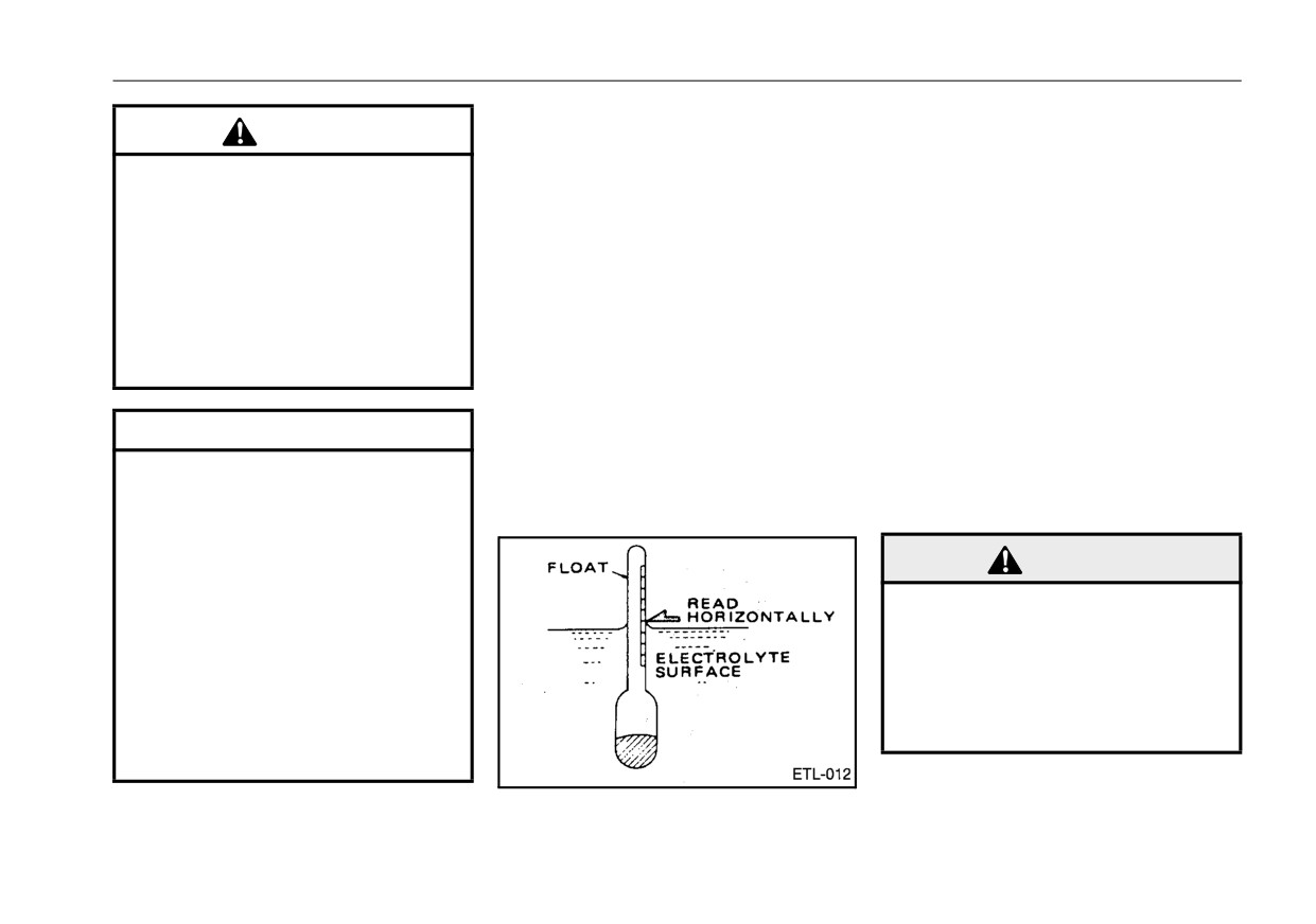
Specific gravity of battery electro-
Cleaning battery terminals
CAUTION
lyte
Periodically inspect the battery
z
Avoid battery acid contact with
The specific gravity of the battery
cables and connectors for corrosion
eyes, skin, wearing materials
electrolyte determines the battery
and tightness. When inspecting the
or painted surfaces. Immedi-
condition. The specific gravity
cables and connections:
ately and thoroughly flush any
decreases as the battery discharges
1.Stop the engine.
contacted area with water. If
and increases as it is charged. The
2.Remove the battery cables and
acid is swallowed or comes
electrolyte temperature also affects
clean contaminated or corroded
into contact with your eyes,
the specific gravity. The specific
terminals. Badly corroded termi-
secure medical help immedi-
gravity of a fully-charged battery is
nals can be cleaned by discon-
ately.
1.280 at
68°F
(20°C). Check the
necting the cables and rubbing
specific gravity of the battery electro-
with a wire brush or sandpaper.
lyte in each cell with a hydrometer. If
CAUTION
Flush any white powder from the
necessary, have the battery checked
terminals with lukewarm water and
z
Do not add water above the
and charged by an authorized UD
specified level. If the battery
Trucks dealer or other qualified ser-
wipe clean.
electrolyte spills, it can cause
vice facility.
damage to the vehicle equip-
ment and body.
WARNING
z
Do not add diluted sulfuric
z When disconnecting the bat-
acid to the battery. This
tery cables, remove the cable
increases the specific gravity
from the negative (-) terminal
of the battery electrolyte and
first. When reconnecting the
shortens the service life of the
cables, attach the cable to the
battery. It also affects specific
negative (-) terminal last.
gravity readings made to
determine battery charge.
11 - 77

-------------------------------------------------------------------------------------------------------------------------------------------------------------

VEHICLE SERVICE AND MAINTENANCE
3.After tightly connecting the cables,
LIGHTS
removal. During this operation, do
apply a thin coat of grease to the
Occasionally it may become neces-
not touch the bulb with bare hands.
terminals to prevent corrosion.
sary to replace a burned out bulb on
your vehicle. When replacing bulbs
with a lens, take care not to over-
tighten lens screws. Overtightening
the screws could damage the lens.
NOTE:
z Use the same number and watt-
age as originally installed.
Refer to "BULBS"on page 13-5.
Headlights
NOTE:
Your vehicle is equipped with halo-
z When the headlight is changed,
Always dispose of automotive batter-
gen headlights.
the light axis must be adjusted.
ies in a responsible manner. Follow
To replace a burned out headlight
If you inevitably replaced it,
your local authorized standard for
bulb:
bring the vehicle for inspection
disposal. Call your local authorized
immediately at the nearest
recycling center to find out more
1.Turn the ignition key and lighting
authorized UD Trucks dealer.
about recycling automotive batteries.
switch to OFF.
2.Tilt the cab.
3.Turn the bulb cover toward OPEN
and remove it.
4.Disconnect the harness connector.
5.While pressing on the set spring,
bring it to the center to take it out.
6.Insert a new bulb into the socket.
Install it in the reverse order of
11 - 78

-------------------------------------------------------------------------------------------------------------------------------------------------------------

VEHICLE SERVICE AND MAINTENANCE
Front turn signal light
3.Turn the socket counterclockwise
Rear combination light
to remove it and replace the bulb
1.Remove the fixing clips (2 loca-
with new one.
tions) from the rubber and turn
over the rubber.
Rear turn signal light
Front side turn signal light
2.Remove the fixing clip from the
lower cover, slide the lower cover
downward and remove it.
11 - 79

-------------------------------------------------------------------------------------------------------------------------------------------------------------

VEHICLE SERVICE AND MAINTENANCE
License plate light
Clearance and identification light
FUSES
The fuse box is located on the lower
portion of main dash and consists of
mini-type fuses.
Also, they are stored in the fusible
link box that is located in front of the
DPF with the muffler installed on the
right side of the chassis.
Open the lid or cover. Labels above
each fuse specify the circuit current
capacity of the fuse to be used in the
circuit.
The fuses are color coded: 5 amp -
Back-up light
Room light
tan; 10 amp - red; 15 amp - blue; 20
amp - yellow; 25 amp - natural and
30 amp - Green; for easy identifica-
tion of current capacity.
Lower portion of main dash
11 - 80

-------------------------------------------------------------------------------------------------------------------------------------------------------------

VEHICLE SERVICE AND MAINTENANCE
CAUTION
z Never connect add-on electri-
cal accessories
(or electrical
circuits) to engine control
fuses or circuits. Doing so
could cause fuses to burn out,
thereby causing a possible
loss of engine and ABS func-
tion.
Inside fusible link box
To replace a blown fuse
2.Install a new fuse with the same
1.Use the fuse puller to remove the
current rating as that specified for
blown fuse.
WARNING
the circuit.
z
When replacing a fuse, never
A new fuse that burns out immedi-
use a fuse with a higher cur-
ately could indicate other problems
rent rating than that specified
in the electrical system. If this
for the circuit. Heat produced
occurs, have the electrical circuits
by currents in excess of circuit
checked by an authorized UD Trucks
capacity can cause fire.
dealer or other qualified service facil-
ity.
11 - 81

-------------------------------------------------------------------------------------------------------------------------------------------------------------

VEHICLE SERVICE AND MAINTENANCE
BLOWER MOTOR FILTERS
Outside air intake filter
the handle into the hole of the
Air filters for a heater or an air condi-
case.
<Method for removal>
tioner are installed behind the front
1.Hold the upper and lower centers
lid at the right side of the cab front.
Inside air intake filter
of the filter with left hand and bend
the filter toward you.
1.Pull the upper and lower two filters
z The air filters for outside air intake
2.Hold the handle at the right end of
toward you.
and inside air intake may cause
the filter with right hand and pull it
2.After cleaning, insert the filter into
clogging due to dirt or dust. Clean
toward you.
the filter slot of the case until it is
them.
locked.
z The installation and removal of the
air filter is a cartridge type.
z Clean the air filter with water or air.
<Installation method>
1.Hold the handle at the left of the fil-
NOTE:
ter and insert the tab around the
z Clogging of the air filter lowers
air flow, resulting in poor perfor-
handle into the hole of the case.
mance of the heater and the air
2.Hold the upper and lower centers
conditioner.
of the filter and bend the filter
z Clean the air filter every
6
toward you.
months or when performance of
3.Hold the handle at the right end of
the heater or the air conditions
the filter and insert the tab around
is poor.
11 - 82

-------------------------------------------------------------------------------------------------------------------------------------------------------------

VEHICLE SERVICE AND MAINTENANCE
WHEELS AND TIRES
Tires
Note that the size charts on the fol-
lowing pages are examples of typical
tire sizes and do not necessarily
apply to your vehicle.
11 - 83

-------------------------------------------------------------------------------------------------------------------------------------------------------------

VEHICLE SERVICE AND MAINTENANCE
Load specification
TIRE LOAD LIMITS AT VARIOUS COLD INFLATION PRESSURES
(The pressure is minimum for the load.)
Current
SI units
Current
SI units
Current
SI units
Current
SI units
Current
SI units
Current
SI units
Current
SI units
Tire size
designation
kPa
660
670
690
720
760
790
830
psi
90
(95)
95
(95)
100
(100)
105
(105)
110
(110)
115
(115)
120
(120)
kgf/cm2
(6.30)
(6.65)
(7.00)
(7.35)
(7.70)
(8.05)
(8.40)
1,550 kg
Dual
-
-
-
-
-
-
-
-
-
-
-
-
-
225/
(3,415 lb)
70R
19.5 (F)
1,650 kg
Single
-
-
-
-
-
-
-
-
-
-
-
-
-
(3,640 lb)
2,650 kg
Dual
-
-
-
-
-
-
-
-
-
-
-
-
-
(5,840 lb)
11R
22.5 (G)
2,800 kg
Single
-
-
-
-
-
-
-
-
-
-
-
-
-
(6,175 lb)
1,950 kg
Dual
-
-
-
-
-
-
-
-
-
-
-
-
-
245/
(4,300 lb)
70R
19.5 (G)
2,060 kg
Single
-
-
-
-
-
-
-
-
-
-
-
-
-
(4,540 lb)
2,120 kg
Dual
-
-
-
-
-
-
-
-
-
-
-
-
-
(4,675 lb)
9R
22.5 (G)
2,240 kg
Single
-
-
-
-
-
-
-
-
-
-
-
-
-
(4,940 lb)
2,300 kg
Dual
-
-
-
-
-
-
-
-
-
-
-
-
-
255/
(5,070 lb)
70R
22.5 (H)
2,500 kg
Single
-
-
-
-
-
-
-
-
-
-
-
-
-
(5,510 lb)
11 - 84

-------------------------------------------------------------------------------------------------------------------------------------------------------------

VEHICLE SERVICE AND MAINTENANCE
Checking the tire pressure and tire
valves when damaged or leaking.
3.Check the tires for uneven or
condition
Replace missing valve caps.
unusual tread wear. Consult the
1.Check the pressure of each tire
2.Check the tire sidewall and tread
table below to determine the cause
with a tire gauge daily. For accu-
for cuts, cracks and damage daily.
of uneven or unusual wear and
rate measurement, check the tires
Remove any foreign objects such
corrective action to be taken. Cor-
when they are cool. Be sure to
as metal, glass and stones
rect the cause of the wear and, if
inflate tires to proper pressure
wedged in the tread grooves and
necessary, replace the tire.
according to the load and inflation
check for tire damage.
pressure table. Check tire valves
Repair or replace as necessary.
regularly for air leaks. Replace
Condition
Cause
Cause Correction
Shoulder wear
z Underinflation
z Inflate
z Sharp turning at high speed
z Reduce speed
z Excessive loading
z Reduce loading
Center wear
z Overinflation
z Inflate
z Slippage due to abrupt braking
z Apply brakes slowly
Diagonal wear
z Incorrect toe-in
z Adjust toe-in
z Imbalanced braking force
z Inspect and adjust service brake
Heel/toe wear
z Incorrect toe-in
z Adjust toe-in or camber
z Underinflation
z Inflate
11 - 85

-------------------------------------------------------------------------------------------------------------------------------------------------------------

VEHICLE SERVICE AND MAINTENANCE
Each tire has six wear indicators.
Checking and retightening the
Check the tread grooves of each tire
WARNING
wheel nuts
daily. Replace a tire when any of the
Loose wheel stud nuts may cause
Do not operate your vehicle:
tread indicators become visible.
shimmy and vibration which can
z With tires inflated in excess of
cause damage to the wheel bear-
the recommendations of the
ings. Retorque the wheel stud nuts
tire or wheel manufacturer.
at the first 1,000 miles (1,600 km) of
z With cut, cracked or damaged
operation. Thereafter, check the nuts
tires.
for tightness every
6,000 miles
z When any of the tire tread wear
(10,000 km) or two months of opera-
indicators are visible.
tion, whichever occurs first and, if
necessary, retorque to specification.
Improperly inflated and dam-
aged tires, and tires with uneven
Using a torque wrench, alternately
or excessive wear may cause
tighten wheel nuts. Do not exceed
blowouts, loss of vehicle con-
wheel nut torque specification. Over-
trol and reduced braking effec-
tightening the wheel nuts will elon-
tiveness. Inspect tires carefully
gate the bolts, deform the wheels
WARNING
and make any necessary repairs
and prevent tightening to the speci-
z
Be
sure
to confirm
that
the
or replacements.
fied torque.
wheel has not been damaged
Tightening torque:
or deformed before putting a
<Front wheel alignment>
UD1800 and UD2000
new tire on it. Follow industry
If abnormal tire wear or ride and han-
273 - 310 ft·lbf (370 - 420 N·m)
and government safety regula-
dling characteristics such as vehicle
(38 - 43 kgf·m)
tions when assembling and
lead or wander are experienced with
UD2300, UD2600 and UD3300
inflating new tires. Failure to
properly inflated tires, the front wheel
398 - 435 ft·lbf (540 - 590 N·m)
do so could result in serious
alignment should be checked.
(55 - 60 kgf·m)
injury or death.
11 - 86

-------------------------------------------------------------------------------------------------------------------------------------------------------------

VEHICLE SERVICE AND MAINTENANCE
z After rotating the position of the
When tire tread pattern is identical
NOTE:
tires, drive the vehicle a dis-
all the way around:
z The wheel nuts on the right side
tance of 30 to 60 miles (50 to 100
of the vehicle have right-handed
km) to settle the wheel disc with
threading; the left side wheel
hub, and then retighten the
nuts have left-handed threading.
wheel nuts to the specified
torque.
Re-tightening procedures for
rear
z The wheel must not be over-
dual nuts
loaded. Pay attention to the total
vehicle load, the weight distribu-
tion related to individual axle
loading and the matching of tire
pressures in the case of dual
wheels.
When tire tread pattern
differs
Tire wear differs depending on
between front and rear:
where the tire is mounted. Rotate the
tire position to allow more even wear
and extend tire life.
1.Loosen the outer wheel nuts.
Tire rotation is recommended every
2.Tighten the inner wheel nuts.
6,000 miles (10,000 km). Shown are
two types of rotation patterns. Use
3.Tighten the outer wheel nuts.
the one best suited to your needs.
After rotation, adjust individual tire
Tire position rotation
pressure as specified in the "Load
specification"on page 11-84. Tighten
NOTE:
wheel stud nuts to the required
z For removal and mounting
of
torque specification and after 1,000
tires, refer to "TIRE CHANGE"on
miles (1,600 km), retorque again to
page 12-6.
specification.
11 - 87

-------------------------------------------------------------------------------------------------------------------------------------------------------------

VEHICLE SERVICE AND MAINTENANCE
z
Replace the hub bolts and nuts
Changing wheel types
WARNING
or wheel disc if the threads are
damaged or deformed or the
z
Never mix different tire size,
wheel disc is deformed or
WARNING
construction or patterns on the
cracked.
same axle.
Use only the same type and style
z
When replacing both dual
z
If tires of different patterns are
wheels and mounting hardware
wheels, make sure that the inner
to be used for the front and
to replace original parts.
wheel nuts are securely tight-
rear, the best combination is to
Do not use unauthorized wheel
ened before installing the out-
use rib type tires for the front
components. Failure to do so
side wheel.
wheels and traction type tires
may result in an assembly which
z
When installing the outside
for the rear wheels.
does not fit together properly
wheel, place the air valve 180°
z
Do not use radial and bias tires
resulting in premature wheel or
apart from the inside wheel.
together.
fastener failures. Mismatched or
z
After mounting dual tires,
incorrect fasteners can result in
ensure that tires do not con-
the vehicle damage or possible
tact each other under a loaded
serious injury.
condition.
z Fasteners like bolts and nuts
removed from the vehicle
should be re-used in the same
NOTE:
spot whenever possible.
z Mount less worn tires on front
If not possible, new fasteners
wheels, and it is advisable to
selected must match those
check the front wheels for the
replaced and obtain good
dynamic balance.
metal-to-metal contact. Do not
z New tires should be used in
attempt to use the fasteners
pairs and mounted on the front
removed from the vehicle for
the vehicle other than UD1800-
wheels first.
UD3300.
z The inflation pressure of a new
tire must be adjusted after
break-in operation.
11 - 88

-------------------------------------------------------------------------------------------------------------------------------------------------------------

VEHICLE SERVICE AND MAINTENANCE
APPEARANCE CARE
NOTE:
It is imperative to identify and
Neglecting body maintenance can
z
Use only soft water for cleaning
use only those fasteners des-
be a major cause of corrosion, which
the vehicle as the use of hard
ignated for use with the
not only makes the vehicle unsightly,
water promotes the deteriora-
respective vehicle being ser-
but can also bring about weakening
tion of rubber parts and fittings.
viced.
of the vehicle’s body and consider-
z
Scrubbing with hard brushes
z
Do not attempt to mix ball seat
ably shorten the vehicle’s life. In
and the like can scratch the
wheels or fasteners with flange
order to prevent corrosion from
vehicle’s painted surfaces.
nut wheels or fasteners.
occurring and/or spreading, we
z
Avoid getting electrical equip-
z
The non-domestic wheel com-
would like to suggest the observance
ment wet. Also, close all doors
ponents on this vehicle are
of the points listed below.
and windows so that water will
similar, but not exactly the
If you should notice any abnormali-
not find its way into gaps.
same as domestic wheels. Do
ties, such as excessive rusting,
z
Carefully wash the vehicle with
not mix non-domestic and
please contact your nearest autho-
water if it has come into contact
domestic parts.
rized UD Trucks dealer or other qual-
with brine, been exposed to sea-
z
Do not change from steel
ified service facility.
water for extended periods, or
wheels to aluminum.
after traveling salted winter
Wash away any accumulated dust,
roads.
sand, mud, etc., with water, paying
When replacing wheels, consult your
z
Repair (paint) chips and other
special attention to joints in the sheet
UD Trucks dealer or qualified service
damage to the vehicle’s painted
metal, wheel wells and runners, and
facility before attempting any wheel
surfaces resulting from flying
edges. After washing, use chamois
or fastener changes.
pebbles and such as early as
or soft cloth to wipe away remaining
possible.
water droplets. Waxing the vehicle
z
Avoid parking the vehicle in
surface also promotes corrosion pre-
direct sunlight, as this can also
vention.
adversely affect the body finish.
We would also like to suggest rinsing
z
Do not wipe the vehicle’s finish
the vehicle with water after driving in
with gasoline or alcohol.
rainy weather or on bad roads.
11 - 89

-------------------------------------------------------------------------------------------------------------------------------------------------------------

VEHICLE SERVICE AND MAINTENANCE
z Be cautious with the use of
garage heaters as their use can
also promote corrosion.
11 - 90

-------------------------------------------------------------------------------------------------------------------------------------------------------------

IN CASE OF EMERGENCY/TROUBLE-SHOOTING
Proper operation of your vehicle,
ENGINE OVERHEATING
IN CASE OF
together with regular inspection and
maintenance, will provide safe and
EMERGENCY/
dependable service for many years.
CAUTION
TROUBLE-
Occasionally a problem may arise
z Do not suddenly stop the
which requires operator action to
SHOOTING
engine when it has overheated.
prevent serious injury, accident and/
Seizure of the engine may
or damage to the vehicle. When a
occur, so keep the engine
problem arises, consult the following
idling until the engine coolant
pages for information to assist you
temperature drops before turn-
with the problem.
ing off the engine.
Hazard Warning Flasher
Use the hazard warning flasher to
Engine coolant temperature
warn other drivers when your vehicle
gauge
presents a safety hazard. If needed,
use flares, portable reflectors, and
z This gauge indicates the engine
other appropriate warnings.
coolant temperature.
To activate the hazard warning flash-
z When the engine coolant tempera-
ers, pull the switch lever located on
ture becomes high while another
the right side of the steering column.
screen is displayed on the multi-
The flasher will operate with the igni-
display, a beep will sound and the
tion key in any position. To turn off
display will automatically change
the hazard warning flashers, pull the
to the engine coolant temperature
switch lever again.
gauge (except when warning is
displayed).
12 - 1

-------------------------------------------------------------------------------------------------------------------------------------------------------------

IN CASE OF EMERGENCY/TROUBLE-SHOOTING
severe) will appear and at
the
the neutral position or P
(Park)
same time, a buzzer sounds.
position.
2.Operate the engine at a fast idle
with the engine throttle knob
located to the right of the steering
column.
3.Following instructions in this man-
ual tilt the cab to provide ventila-
tion.
4.Stop the engine when the engine
coolant temperature drops to the
z
If the engine coolant tempera-
normal range on the gauge.
ture
(ECT)
significantly
5.After the engine and cooling sys-
increases, an overheat warning
tem have cooled, open the radiator
with a
2-phase indication
CAUTION
cap.
(amber: moderate, red: severe)
z
Do not drive while the engine
If the engine coolant level is below
will appear.
overheat warning is displayed.
the bottom of the filler neck, add
The engine protection func-
coolant and take necessary cares
Warning message or light
tion may provide torque derat-
by following instructions steps 2-4
If the temperature gauge indicator is
ing to prevent the engine from
in the section, "Engine coolant
in the high temperature zone, keep
being damaged, so have it
level warning light" on page 7-45.
the engine idling and do not stop the
inspected and serviced by the
engine until the indicator falls into
nearest authorized UD Trucks
the suitable range.
dealer.
z When the engine overheats, an
overheat warning with a 2-phase
1.Immediately stop the vehicle in a
indication (amber: moderate, red:
safe place. Apply the parking
brake and shift the transmission to
12 - 2

-------------------------------------------------------------------------------------------------------------------------------------------------------------

IN CASE OF EMERGENCY/TROUBLE-SHOOTING
JUMP STARTING
z
Be extremely careful when
opening the radiator filler cap.
Place a thick cloth on the cap
Emergency Starting
and slowly loosen it to allow a
reduction in pressure
in
the
cooling system.
DANGER
Batteries produce explosive
gases. To minimize risk of seri-
ous injury or death:
z
Keep sparks and open flame
away from the batteries. Never
smoke when working on or
WARNING
around the batteries.
z
Make sure that adequate venti-
To avoid serious injury from hot
lation is provided when work-
coolant or steam release:
ing on or around the battery in
z Do not open the radiator filler
an enclosed area.
cap while the engine cooling
z
Do not permit metal tools to
system is still hot; wait until it
simultaneously contact the
cools.
positive battery terminal and
If the radiator cap is removed
any other metal on either vehi-
right after the engine is shut
cle at the same time.
off, scalding fluid and steam
z
Always wear eye protection
may blow out under pressure
when working near batteries.
and cause serious burn inju-
ries.
12 - 3

-------------------------------------------------------------------------------------------------------------------------------------------------------------

IN CASE OF EMERGENCY/TROUBLE-SHOOTING
ness. Tighten the connectors and
WARNING
remove corrosion as necessary.
WARNING
Turn off all electrically operated
z
Do not use ether or other start-
z
Do not attempt to jump start a
equipment and accessories and
ing aids which are flammable.
vehicle having a frozen bat-
attempt to start the engine.
z
The engine should never be
tery; the battery may rupture or
When the engine still cannot be
explode.
started by pushing or towing
started because of a discharged bat-
z
Route the jumper cables to
the vehicle. Since with the
tery, use the following procedure to
avoid parts such as fans and
engine stopped the effective-
jump start the vehicle with the dis-
belts which will move when the
ness of the service brake sys-
charged battery.
engines are started.
tem is seriously reduced and
z
Your vehicle has a 12-volt neg-
the power steering requires
ative ground electrical system
greater effort than in normal
(two
12 volt batteries con-
conditions.
nected in parallel). Make sure
that the other vehicle also has
a 12-volt negative ground elec-
CAUTION
trical system. Do not attempt
to jump start either vehicle if
z
Do not hold the ignition key at
you are unsure of the other
the START position continu-
vehicle’s voltage or grounding
ously for more than 15 sec-
system.
onds. Extended cranking will
z
Do not use jumper cables
shorten the life of the battery
which have been damaged or
are not properly insulated.
and damage the starting sys-
tem. If the engine cannot be
started on the first try, wait 30
seconds and try again.
Before attempting to jump start a
vehicle, check the battery cables and
connections for corrosion and tight-
12 - 4

-------------------------------------------------------------------------------------------------------------------------------------------------------------

IN CASE OF EMERGENCY/TROUBLE-SHOOTING
<To jump start a vehicle>
5.Start the engine of the vehicle with
6.After your engine is started,
the good battery. After increasing
remove the jumper cables in the
1.Position the vehicles so that the
to a moderate engine speed, start
reverse order of connection.
jumper cables can be attached. Do
the vehicle
with
the
discharged
7.Charge the discharged battery at
not allow the vehicles to come into
battery.
an authorized UD Trucks dealer or
contact with one another.
other qualified service facility.
2.Turn off the ignitions of both vehi-
cles and apply the parking brakes.
3.Connect one end of one jumper
cable to the red positive (+) termi-
nal of the discharged battery and
the other end to the red positive
terminal of the good battery.
4.Connect one end of the second
jumper cable to the grounded
black negative (-) terminal of the
good battery. Connect the other
end of the second cable to the
frame of the vehicle with the dis-
charged battery at a location as
distant from the battery as possi-
ble. Confirm that the cables are
routed such that they will not come
into contact with fans, belts, or
other moving parts when the
engines are started.
12 - 5

-------------------------------------------------------------------------------------------------------------------------------------------------------------

IN CASE OF EMERGENCY/TROUBLE-SHOOTING
TIRE CHANGE
z An inflated tire contains air
under high pressure. An
WARNING
inflated tire and wheel can be
Damaged tire
To avoid serious injury when
dangerous if misused, and can
jacking up your vehicle:
result in serious injury and/or
WARNING
z
Never start the engine or get
property damage.
under your vehicle while it is
z
Avoid full or panic braking if
The maintenance of a dam-
supported by a jack.
you have a flat tire while driv-
aged tire and wheel requires
z
Select a flat, hard surface
ing since this may cause loss
the use of proper tools, safe
when using a jack.
of vehicle control.
equipment, and tire service
z
Place chocks at both the front
Cautiously pull your vehicle off
expertise.
and back of the tire diagonally
the road while paying attention
opposite the tire being
to other traffic. Hold the steer-
To replace a tire, refer to the follow-
replaced.
ing wheel firmly and park the
ing instructions.
z
While jacking up the vehicle,
vehicle in a level and safe
Jack operating instructions
do not load or unload cargo.
place. Apply the parking brake
Follow the jacking instructions in this
The jack might come off by
firmly, turn on the hazard warn-
manual as well as the instructions of
vibration and shifting of the
ing flasher switch and stop the
the jack manufacturer.
center of gravity.
engine.
z
When lowering the vehicle, do
z
If the vehicle is operated con-
not open the release valve fully
tinuously with a flat tire, it may
at one time. The vehicle might
become hot, causing the tire to
drop rapidly, causing the jack
ignite or burst. This is very
to come off.
dangerous.
12 - 6


Content      ..     12      13      14      15     ..