UD Trucks. Owner’s Manual (2011-2013) - page 12


  Главная      Manuals     UD Trucks. Owner’s Manual (VEHICLE SERVICE AND MAINTENANCE) (2011-2013)


Search            copyright infringement  


Content      ..     10      11      12      13     ..


UD Trucks. Owner’s Manual (2011-2013) - page 12


-------------------------------------------------------------------------------------------------------------------------------------------------------------
VEHICLE SERVICE AND MAINTENANCE
FUEL SYSTEM
Fuel tank
WARNING
Water in the diesel fuel will accumu-
z After replacement of the oil fil-
WARNING
late at the bottom of the fuel tank. A
ter, operate the engine to
small area near the drain cock traps
check if there is any oil leak-
z Keep flames and heat away
the water. When water has accumu-
age around the oil filter. Oil
from the fuel system since the
lated in the fuel filter, it has also
leakage can cause a fire.
fuel is flammable and can
accumulated in the fuel tank. Drain
cause a fire or explosion.
the accumulated water from the fuel
7.Stop the engine and wait at least
tank when the fuel filter is drained.
10 minutes.
To minimize loss of fuel, drain the
A problem with the components that
fuel tank as it approaches empty. Do
Recheck the level and fill to the
supply fuel to the engine can cause
not re-use any fuel drained with the
MAX mark if necessary.
low fuel pressure. This can decrease
water.
engine performance.
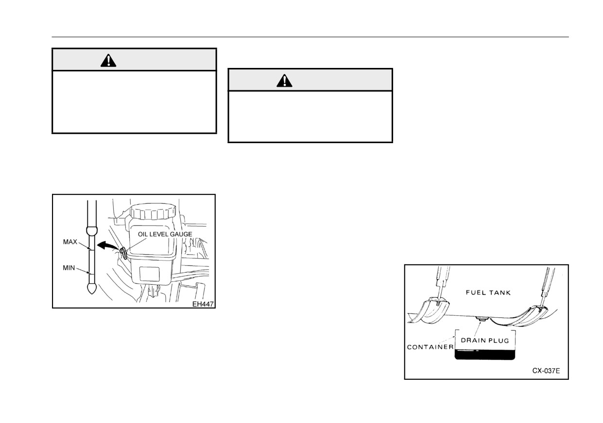
To drain water from the fuel tank
1.Check the fuel level in the fuel
1.Put a container under the fuel tank
tank. Make sure the breather valve
drain plug.
of the fuel tank is not clogged with
2.Remove the drain plug from the
dirt.
bottom of the fuel tank.
2.Check the fuel lines for fuel leak-
age. Be sure the fuel supply line
does not have a restriction or a
bad bend.
z Wipe any spilled oil off the engine.
z Do not run the engine with the oil
level below the MIN mark, or with
the filler cap and/or level gauge
removed.
11 - 37

-------------------------------------------------------------------------------------------------------------------------------------------------------------

VEHICLE SERVICE AND MAINTENANCE
3.Allow all the water to drain from
Fuel requirements
the tank.
Use only ultra-low sulfur diesel fuel
WARNING
4.When fuel begins to drain from the
which contains less than
15 ppm
tank, replace the drain plug.
(parts per million) by volume of sul-
z Do not use ether or other start-
Tighten the drain plug.
ing aids which are flammable.
fur.
Tightening torque:
36 to 51 ft·lbf (49 to 69 N·m) (5 to
CAUTION
7 kgf·m)
CAUTION
z The
aftertreatment
DPF*
requires diesel fuel with a sul-
z Use diesel fuel only. Do not
fur content of less than 15 ppm
use gasoline or any other non-
WARNING
(0.0015%) by weight. If the sul-
diesel fuel.
z
Wipe off any leaked fuel, as it
fur content is higher than 15
NOTE:
could cause a fire.
ppm (0.0015%) by weight, the
z
Fuel additives should not be
DPF system and engine may
used.
be damaged.
CAUTION
z
For prolonged idling operation,
DPF*: Diesel Particulate Filter sys-
operation in temperatures below
z
Check the packing of the drain
tem
32°F (0°C), or operation in high
plug for damage. If damaged,
altitude areas (above 5,000 ft.,
Use good quality ASTM 2-D
replace with a new one.
1,500 m), winterized 2-D may be
Expected
Preferred fuel grade
used.
temperature
z
If gasoline is put into the fuel
Above
Grade Ultra Low Sulfur
+20°F (-7°C)
Grade 2-D S15
tank by mistake, completely
drain the fuel system to remove
Below
Grade Ultra Low Sulfur
+20°F (-7°C)
Grade 1-D S15
the gasoline.
Use diesel fuel with cetane number
45 or higher. Check with the service
establishment to be sure you get the
properly blended fuel for the season.
11 - 38

-------------------------------------------------------------------------------------------------------------------------------------------------------------

VEHICLE SERVICE AND MAINTENANCE
Keep fuel clean and prevent water
Fuel filling
CAUTION
from entering the fuel system.
z Never operate your vehicle
Feeding clean fuel to the engine
WARNING
without a fuel cap. If the fuel
depends both upon the supplier and
cap needs to be replaced, use
the user.
z Keep flames and heat away
a UD Trucks cap or an equiva-
For example, when fuel is supplied
from the fuel system since the
lent. Use of an incorrect fuel
from a corroded storage tank, the
fuel is flammable.
cap could result in a fuel sys-
fuel should be filtered before it is put
Any of these can result in seri-
tem or emission control sys-
into the fuel tank of the vehicle.
ous injury and/or property
tem malfunction.
Water in fuel adversely affects the
damage due to fire.
fuel injection system and engine.
z Wipe off any leaked fuel, as it
Fuel filter
Water and dirt should be removed
could cause a fire.
from fuel contaminated during stor-
Your UD Trucks vehicle is equipped
age.
Keeping your fuel tank filled with fuel
with a main fuel filter and primary
When filling the fuel tank in the rain
will help reduce condensation within
fuel filter with water separator.
or snow, care should be taken not to
the tank.
The fuel filters remove dirt and the
allow water in the fuel tank.
water separator removes water from
Do not forget to screw on the fuel
Fuel cap
the fuel.
tank cap securely.
NOTE:
z Failure to perform periodic
WARNING
maintenance can cause fuel fil-
z Use of an incorrect fuel cap or
ters to clog and the fuel supply
operating the vehicle without a
to decrease or to stop.
fuel cap could result in a fire.
Periodic maintenance of the fuel fil-
ter should be performed.
If the fuel is contaminated with dirt,
more frequent maintenance on fuel
11 - 39

-------------------------------------------------------------------------------------------------------------------------------------------------------------

VEHICLE SERVICE AND MAINTENANCE
filter is required as shown in
Main filter
z
Use a filter wrench to loosen
"Engine"on page 11-4.
To replace the fuel filter
the fuel filter. Use of an ordi-
If you are not certain concerning the
nary tool (for example, chain-
proper interval, contact your autho-
type tool) can scratch or dent
rized UD Trucks dealer. Use genuine
the peripheral surface of the
UD Trucks fuel filters or equivalent.
fuel filter. If the fuel filter is
Consult your authorized UD Trucks
damaged, it can cause fuel to
dealer regarding the quality and
leak.
interchangeability of fuel filters.
z
After replacing the filter,
inspect the external surface of
the fuel filter checking for
WARNING
scratches and dents. It is dan-
Fuel is flammable and can cause
gerous to use a scratched or
fire or explosion. To minimize
dented fuel filter, since it can
1.Clean outside the filter not to get
this hazard, do the following:
cause fuel to leak.
dust into the filter at the disassem-
z Be sure to drain the fuel into a
z
After replacement of the ele-
bly. Prepare a tray for drained fuel
container and dispose of it
ment, operate the engine to
(approx. 2.1 qt
[2.0 liter]) and a
properly.
check if there is any fuel leak-
hose (inner diameter 0.2 in [5 mm],
z If fuel is spilled on engine
age around the fuel filter.
length 3.3 ft [1 m]).
parts, wipe it off entirely.
Inspect the water level in the fuel fil-
2.Put the hose in the drain plug, and
z Do not smoke when perform-
ing maintenance on the fuel
ter daily through the transparent
loose the drain plug and air purge
system. Keep flame and heat
case. Drain water before it reaches
plug to drain the fuel. The fuel will
away from the fuel system.
the upper portion of the transparent
be received by the tray.
[loosen
case.
until you can see an o-ring on the
plug (approx. 0.2 in [5 mm]).
3.After draining, loosen the case and
remove the case and element from
the housing.
11 - 40

-------------------------------------------------------------------------------------------------------------------------------------------------------------

VEHICLE SERVICE AND MAINTENANCE
4.Install a new o-ring for the case
Primary fuel filter
WARNING
lubricating it with clean diesel fuel.
To drain water from the fuel filter
5.After putting a new element into
z
Using improper fuel filters can
the case, place it to the housing
shorten the life of the engine
and tighten the case to the follow-
and/or fuel injection system.
ing torque.
Such fuel filters can become
Tightening torque:
damaged or may leak fuel
26 to 29 ft·lbf (35 to 40 N·m)
which can result in serious
injury and/or property damage
(3.6 to 4.1 kgf·m)
due to fire.
6.Tighten the drain plug and air
purge plug securely by hand.
7.After the filter change, purge the
air from the fuel system. For air
purging details, refer to "Purging
1.Stop the engine, prepare a tray to
air from fuel system"on page 11-
receive drained water.
43.
2.Loosen the drain plug and drain
8.Start engine and check the fuel
the water (approx. 6.8 USfl oz [200
system for leaks.
milli liter] into the tray).
3.After finish the draining, tighten the
drain plug securely by hand.
11 - 41

-------------------------------------------------------------------------------------------------------------------------------------------------------------

VEHICLE SERVICE AND MAINTENANCE
To replace the fuel filter
ing torque.
WARNING
Tightening torque:
26 to 29 ft·lbf (35 to 40 N·m)
z
Using improper fuel filters can
(3.6 to 4.1 kgf·m)
shorten the life of the engine
6.Tighten the drain plug surely by
and/or fuel injection system.
hand.
Such fuel filters can become
7.Remove the fuel inlet plug on top
damaged or may leak fuel
of the filter and pour diesel fuel
which can result in serious
injury and/or property damage
fully in it, and tighten the plug to
due to fire.
the following torque.
Tightening torque:
1.7 to 2.5 ft·lbf (2.3 to 3.4 N·m)
1.Clean outside the filter not to get
(0.2 to 0.3 kgf·m)
dust into the filter at the disassem-
8.After the filter change, purge the
bly. Prepare a tray for drained fuel
air from the fuel system. For air
(approx. 2.1 qt [2.0 liter]).
purging details, refer to "Purging
2.Loosen the drain plug to drain the
air from fuel system"on page 11-
fuel. The fuel will be received by
43.
the tray.
9.Start engine and check the fuel
3.After draining, loosen the case and
system for leaks.
remove the case and element from
the housing.
4.Change the o-ring for case to new
one and put some clean diesel on
the new o-ring.
5.After putting a new element into
the case, place it to the housing
and tighten the case to the follow-
11 - 42

-------------------------------------------------------------------------------------------------------------------------------------------------------------

VEHICLE SERVICE AND MAINTENANCE
Purging air from fuel system
2.Put the hose in the air purge plug
Fuel hose and clamp
and loose the plug. Let the other
If air gets into the fuel system, it will
Check the fuel rubber hose and
side of the hose get into the tray.
cause inconsistent fuel injection and
clamp of the fuel system for loose-
(loosen until you can see an o-
possible engine malfunction. It is
ness cracks or damage. Replace
rings on the plug).
therefore necessary that any air be
faulty parts if necessary.
bled off which may have found its
3.Push the priming pump then the
way into the fuel system while
fuel is pumped up from the tank
changing fuel filters, or when the fuel
and get into the filter.
WARNING
lines have been otherwise discon-
4.Keep pushing the priming pump
z Keep flames and heat away
nected.
until clear fuel with no air is exiting
from the fuel system since the
the air purge plug.
fuel is flammable.
To purge air from the fuel system
5.After the air has been removed,
Any of these can result in seri-
tighten the air purge plug securely
ous injury and/or property
by hand.
damage due to fire.
z Wipe off any leaked fuel, as it
could cause a fire.
Fuel tubing
Check the fuel tubing for fractures,
damage or improper installation.
Replace faulty parts if necessary.
Whenever the fuel tubing is discon-
nected, be sure to purge air from the
1.Prepare a tray for drained fuel
fuel system.
(approx. 2.1 qt
[2.0 liter]) and a
hose (inner diameter 0.2 in [5 mm],
length 3.3 ft [1 m]).
11 - 43

-------------------------------------------------------------------------------------------------------------------------------------------------------------

VEHICLE SERVICE AND MAINTENANCE
AIR CLEANER ELEMENT
CAUTION
WARNING
To inspect the air cleaner service
z If the viscous type (wet type)
z Keep flames and heat away
indicator
element is sprayed with com-
from the fuel system since the
The air cleaner service indicator is
pressed air, washed, hit, or
fuel is flammable.
installed near air cleaner.
struck, the filter function can
Any of these can result in seri-
Check whether a red signal is shown
be seriously deteriorated, and
ous injury and/or property
on the service indicator for clogging
early clogging may occur.
damage due to fire.
of the air cleaner element.
z
Wipe off any leaked fuel, as it
If the dust indicator signal is red, and
could cause a fire.
if it often becomes red after resetting
1.Unlock the clips and remove the
by pushing the button on the end,
air cleaner cover.
replace the element.
2.Remove the element.
To replace the air cleaner element
Never clean the viscous type (wet
type) air cleaner element.
11 - 44

-------------------------------------------------------------------------------------------------------------------------------------------------------------

VEHICLE SERVICE AND MAINTENANCE
or be damaged by excessive
NOTE:
tightening.
z If the vacuator valve is broken
or missing, water and dirt can
7.Reinstall the new element in the
easily enter the air cleaner.
Install a new vacuator valve.
reverse sequence of removal.
z Be sure that all three clips are
locked securely when replacing
the element and housing cover.
z Install the rubber seal so that it
may not be twisted.
3.Clean the cover and inside of the
CAUTION
case with a clean, dry cloth.
z Failure to completely install
the clips may cause a defect in
the element packing surface,
allow dust into the engine, and
5.Check the rubber seal and hose
cause premature wear of pis-
for breakage and the clamps for
tons and liners.
looseness. If broken, replace it
with a new part. If the clamps are
8.After finishing replace of the ele-
loose, tighten them.
ment, press the reset button at the
6.Replace the element.
end of the indicator to reset.
NOTE:
z Be sure to use genuine UD
4.Clean the vacuator valve. Be sure
Trucks element. Do not use an
it is not broken or missing.
inferior element because it may
aspirate dust due to a bad seal
11 - 45

-------------------------------------------------------------------------------------------------------------------------------------------------------------

VEHICLE SERVICE AND MAINTENANCE
DRIVE BELT
meter”. For daily inspections
without the sonic tension meter,
checking the amount of deflec-
tion of the belt using a hand is
allowed.
Check air conditioner belts for proper
tension by applying pressure of 22
lbf (98 N) (10 kgf) with your finger to
the belt at measuring as shown in
the figure. If necessary, adjust them
to their specified tensions.
WARNING
z Do not check or adjust drive
belt, unless engine is off and
the transmission is in N (Neu-
tral).
Engage the parking brake securely.
Visually check the drive belt daily for
cracks and damage. If a belt is in
poor condition, have it replaced by
an authorized UD Trucks dealer or
other qualified service facility.
NOTE:
z The belt tension measurement
is recommended to be per-
formed using a “sonic tension
11 - 46

-------------------------------------------------------------------------------------------------------------------------------------------------------------

VEHICLE SERVICE AND MAINTENANCE
Air conditioner belt tension
When measuring with a sonic tension meter
Belt deflection
Specific weight
22 lbf (98 N) (10 kgf) by
Belt
Frequency
Length of span
Number of ribs
of the belt
depressing
(Hz)
in (mm)
in (mm)
(gf/rib·m)
When new
202 - 216
0.32 - 0.36 (8.2 - 9.1)
4
10.7 (272)
14.5
When adjusted
175 - 187
0.39 - 0.43 (10 - 11)
To adjust belt tension
Fan belt
Because this engine is equipped
Air conditioner belt:
with a belt tensioner, the adjustment
of belt deflection is not necessary.
1.Loosen the lock nut A of the idler
However, it is necessary to confirm
pulley.
that the indicator (engraved line) of
2.Adjust the adjusting bolt B and
the belt tensioner is in the belt
adjust the deflection of the belt at
usable range by performing the
measuring point Y so that it comes
visual check from the X position (X
within the standard range.
arrow view). Also, check the belt for
The tension of the belt can be
damage at this time.
increased by turn the adjusting bolt
3.After adjustment, securely tighten
B clockwise.
the lock nut A.
Tightening torque:
Lock nut A
22.4 to 28.9 ft·lbf
(30.4 to 39.2 N·m)
(3.1 to 4.0 kgf·m)
11 - 47

-------------------------------------------------------------------------------------------------------------------------------------------------------------

VEHICLE SERVICE AND MAINTENANCE
z If there are any abnormalities of
AFTERTREATMENT DEF
pulleys motion.
FILTER
z If the pulleys do not return when
releasing the belt.
Replacement of DEF filter
The main filter is provided under the
supply module
(DEF pump).
Replace the filter on a regular basis.
If the indicator (raised line) is out of
stretched belt indicator, or if the belt
is damaged, replace the belt with a
new one.
To inspect the belt tensioner
Push down the belt between the pul-
leys with a constant force. Check to
see that the tension pulleys move
NOTE:
with constant speed.
z DEF is a very safe liquid, but it
Then release the belt and check to
might cause a very slight irrita-
see that the tension pulleys return to
tion for some people. If it is
the original position by the spring
spilled on the body, wash it off
force.
with water, and if it is drunk mis-
Replace the belt tensioner when any
takenly, drink
1 or 2 cups of
of the following conditions exist.
milk. If milk is not available,
z If the pulleys do not move when
drink water. In all case, consult a
pushing down the belt.
physician.
11 - 48

-------------------------------------------------------------------------------------------------------------------------------------------------------------

VEHICLE SERVICE AND MAINTENANCE
z To prevent dirt getting into the
DEF system, clean the DEF lines
and the DEF tank before remov-
ing them.
z Always plug DEF lines to pre-
vent dirt getting into the DEF
system and the crystallization of
the DEF.
Replacement procedure
1.Switch off the engine.
NOTE:
4.Remove the equalizing element.
6.Clean the sealing surface of the
z Wait at least two minutes before
housing with water only.
removing DEF hoses to allow
the automatic draining of the
DEF system and to depressurise
the DEF system.
2.Disconnect all electrical power to
the vehicle by disconnecting the
battery negative (-) terminal.
Fetch equipment and place a suit-
able container under the DEF
pump.
5.Insert the puller, and remove the
3.Remove the filter cover from the
filter using the puller.
7.Install the new filter.
pump.
11 - 49

-------------------------------------------------------------------------------------------------------------------------------------------------------------

VEHICLE SERVICE AND MAINTENANCE
on the cover.
CCV FILTER
Tightening torque:
15 to 18 ft·lbf (20 to 25 N·m)
Replacement of CCV filter
(2.0 to 2.5 kgf·m)
The CCV (blow-by gas reducing sys-
tem) filter captures oil contained in
blow-by gas. Replace it on a regular
basis.
8.Apply a thin film of engine oil to the
o-ring on the new equalizing ele-
ment.
Install the new equalizing element.
10.Connect the battery negative (-)
terminal.
11.Start the engine and ensure there
is no leakage.
1.Clean the area around the CCV fil-
ter cap to prevent dirt from enter-
NOTE:
ing during replacement.
z If any DEF splashed onto any
part, completely wipe it off.
2.Turn the filter cap counterclock-
wise for removal and replace the
element.
3.After replacing the cap O-ring with
a new one, apply engine oil lightly
9.Install the filter cover. Tighten the
and install the cap. Tighten the cap
filter cover to the torque specified
11 - 50

-------------------------------------------------------------------------------------------------------------------------------------------------------------

VEHICLE SERVICE AND MAINTENANCE
securely
until it is raised
and
TRANSMISSION GEAR OIL
NOTE:
stopped.
z
Since blow-by gas, which is
reduced after intake, includes a
WARNING
trace of oil mist, oil comes in
contact with the inner surfaces
z To avoid possible burn injury,
of the air intake parts even
allow the transmission to cool
under normal operation environ-
before checking or changing
ment due to operation over a
the transmission oil.
long period of time. This is not a
failure.
Check the vehicle daily for transmis-
sion oil leakage. If there is any evi-
dence of oil leakage, locate and
correct the cause. Visually check the
transmission oil level. If low, add oil
CAUTION
until the level reaches the bottom of
the filler plug hole.
z
Be sure to turn the filter cap by
hand. Use of a tool may dam-
To check the manual transmission
gear oil level
age the cap.
z
Be sure to replace the element
1.Remove the transmission filler
at the specified time. Use of
plug and visually check that the oil
the element after the replace-
level reaches the bottom of the
ment period may cause clog-
filler hole.
ging of the element, resulting
in increase of oil mist in the
blow-by gas that is reduced
after intake.
11 - 51

-------------------------------------------------------------------------------------------------------------------------------------------------------------

VEHICLE SERVICE AND MAINTENANCE
3.Reinsert the plug and tighten the
To check the automatic transmis-
sion fluid level (Allison 1000, 2200
plug.
and 2500 series)
Tightening torque:
z
Check the fluid while the vehicle is
UD1800 thru UD3300
on level ground and the parking
MLS63
72 to 89 ft·lbf (98 to 120 N·m)
brake applied. Start the engine and
(10 to 12 kgf·m)
run for at least one minute at 900
UD2600 and UD3300
to 1,000 rpm to clear the system of
MLS63
air. Shift the transmission to Drive,
72 to 94 ft·lbf (98 to 130 N·m)
Reverse, and then to Neutral to fill
(10 to 13 kgf·m)
the clutch cavities and fluid pas-
MPS63
sages.
CAUTION
87 to 101 ft·lbf (118 to 137 N·m)
z
Always clean around the end of
(12 to 14 kgf·m)
the filler tube before removing the
z
To prevent dirt and debris from
entering the transmission,
dipstick. Dirt or foreign matter must
clean the filler plug, transmis-
not be permitted to enter the fluid
sion housing, and surrounding
system. It can cause valves to
area before checking.
stick, cause undue wear of trans-
z
If the transmission oil level is
mission parts, or clog passages.
low, the transmission will not
Check the fluid level by one of the
operate normally and could
following procedures and report
malfunction. Check to deter-
any abnormal fluid level to your
mine the cause of low oil level.
maintenance personnel.
Correct the condition before
operating the vehicle.
2.After checking the oil level, replace
the filler plug gasket with a new
one.
11 - 52

-------------------------------------------------------------------------------------------------------------------------------------------------------------

VEHICLE SERVICE AND MAINTENANCE
operated until a hot check can
NOTE:
be made.
z
The fluid must be hot to ensure
an accurate check. The fluid
z
A cold fluid check may be made
level rises as temperature
when engine coolant temperature
increases.
gauge starts to move. (Reference;
approximately 86°F: 30°C)
z
Park the vehicle on a level spot,
z
Run the engine for at least 1 min-
shift to
(N) neutral and apply the
ute to clear the fluid system of air.
parking brake. Let the engine run
z
With the engine running at idle,
at idle speed.
wipe the dipstick clean and check
z
Wipe the dipstick clean and check
the fluid level. Any level within the
the fluid level. The safe operating
COLD band is satisfactory for
level is any level within the HOT
operating the vehicle. If the level is
band on the dipstick.
not within the COLD band, add or
z
If not within this range, add or
drain fluid as necessary to bring
the level to the middle of the COLD
the level to the middle of the HOT
band.
band.
z
Perform a hot check at the first
opportunity after driving vehicle for
at least
30 minutes. (Reference;
Sump temperature is
160 to
<COLD CHECK>
200°F: 71 to 93°C.)
NOTE:
<HOT CHECK>
z The purpose of the cold check is
z Operate the transmission in a drive
to determine if the transmission
range for at least 30 minutes to get
has enough fluid to be safely
operating temperature.
(Refer-
ence; 160 to 200°F: 71 to 93°C)
11 - 53

-------------------------------------------------------------------------------------------------------------------------------------------------------------

VEHICLE SERVICE AND MAINTENANCE
To check the automatic transmis-
fluid level is within the COLD band
sion fluid level (Allison 3000 series)
range. If the fluid level is not within
the range, refill fluid.
Inspection with the fluid dipstick
z
Check the fluid while the vehicle is
<HOT CHECK>
on level ground and the parking
z
After warming up the engine and
brake applied. Start the engine and
driving for about 10 to 15 minutes,
run for at least one minute at 900
pull the fluid dipstick out of the filler
to 1,000 rpm to clear the system of
tube, wipe fluid off the dipstick sur-
air.
face, and then insert the dipstick
z
Idle the engine.
back in the original position.
z
With the engine at idle, depress
z
Pull out the fluid dipstick again to
the brake pedal and shift the range
inspect the fluid level. Check (at
to D (Drive) or R (Reverse) to fill
least twice) to make sure that the
the whole hydraulic circuit with
fluid level is within the HOT band
fluid.
range.
z
Shift the range to N (Neutral).
z
If the fluid level is within the HOT
z
With the engine at idle and the
band range, the inspection is com-
range in the N (Neutral) position,
pleted. If the fluid level is not within
inspect the fluid level.
the range, refill fluid.
<COLD CHECK>
z Pull the fluid dipstick out of the filler
tube, wipe fluid off the dipstick sur-
face, and then insert the dipstick
back in the original position.
z Pull out the fluid dipstick again to
inspect the fluid level. Check (at
least twice) to make sure that the
11 - 54

-------------------------------------------------------------------------------------------------------------------------------------------------------------

VEHICLE SERVICE AND MAINTENANCE
stop on a level ground, and then
CAUTION
shift to the N (Neutral) range.
z
Before the inspection, be sure
z
The vehicle has been stationary for
to apply the parking brake.
about 2 minutes to allow the fluid
Then, while the engine is run-
to settle.
ning at idle, conduct the
z
Run the engine at an idle.
inspection. If the inspection is
z
Push the and switches
of
conducted while the engine
stops, the apparent amount
the selector at the same time.
becomes large.
z
If
the fluid temperature
increases, the fluid level
Fluid level is proper:
increases. Be sure to conduct
“O L” “O K” “O K” are displayed by
a final check while the fluid
two letters in sequence, 6 letters in
temperature is high after
total, on the digital display.
warming-up.
z
Before the inspection, clean
Fluid level is low:
around the end of the filler
“O L” “L O” “O 1” are displayed by
tube to prevent dust, mud or
two letters in sequence, 6 letters in
water from entering the filler
total, on the digital display. If the last
tube. If dust, mud or water
NOTE:
figure is 1, 1 quart of fluid must be
enters, a failure of the trans-
z To recover the fluid level check
added.
mission may be caused.
mode, push the N switch of the
Fluid level is high:
selector.
“O L” “H I” “O 2” are displayed by two
Inspection with the electronic fluid
letters in sequence, 6 letters in total,
level sensor
z If the measuring conditions have
on the digital display. If the last figure
z Warm up the engine, drive the
been satisfied, the results will be
is
2,
2 quarts of fluid must be
vehicle for about 10 to 15 minutes,
displayed on the digital display
released.
about 2 minutes later.
11 - 55

-------------------------------------------------------------------------------------------------------------------------------------------------------------

VEHICLE SERVICE AND MAINTENANCE
z
If the measuring conditions have
Manual transmission gear oil
not been satisfied, “O L” “ --
change
“E L” are displayed by two letters
To change the manual transmis-
in sequence, 6 letters in total, on
sion gear oil
the digital display. The meanings
of the last two figures are as indi-
WARNING
cated in the following table.
z To avoid possible burn injury,
allow the transmission to cool
Code
Cause of code
before checking or changing
the transmission oil.
“X
Waiting period is not complete
“E L”
Engine speed (rpm) too low
1.Place a container under the drain
plug. Remove the drain plug and
“E H”
Engine speed (rpm) too high
completely drain the transmission
“S N”
N (Neutral) must be selected
oil.
“O L”
--
“T L”
Sump fluid temperature too low
“T H”
Sump fluid temperature too high
“S H”
Output shaft rotation
Sensor failure (may be speed sensor, throttle sensor,
“F L”
temperature sensor, or oil level sensor but this indi-
cation does not identify which has failed)
: The display is a flashing numeral, counting down from 8 to 1 until the
waiting period is complete.
11 - 56


Content      ..     10      11      12      13     ..