UD Trucks. Owner’s Manual (2011-2013) - page 13


  Главная      Manuals     UD Trucks. Owner’s Manual (VEHICLE SERVICE AND MAINTENANCE) (2011-2013)


Search            copyright infringement  


Content      ..     11      12      13      14     ..


UD Trucks. Owner’s Manual (2011-2013) - page 13


-------------------------------------------------------------------------------------------------------------------------------------------------------------
VEHICLE SERVICE AND MAINTENANCE
2.After draining, replace the gasket
Oil refill capacity (Approximately)
Automatic transmission fluid
of the drain plug with a new one.
filter (Allison 1000, 2200 and 2500
Oil capacities
PTO
Reinsert the plug and tighten the
US qt (liters)
series)
plug.
Without
7.2
(6.8)
MLS63
Tightening torque:
With
7.8
(7.3)
WARNING
UD1800 thru UD3300
Without
8.3
(7.8)
MPS63
MLS63
With
8.8
(8.3)
z Do not handle hot filter without
72 to 89 ft·lbf (98 to 120 N·m)
hand protection. Failure to do
(10 to 12 kgf·m)
4.Visually check the oil level and add
so may result in burn injury.
UD2600 and UD3300
oil, if necessary, until it reaches the
MLS63
bottom of the filler plug hole.
To replace the filter
72 to 94 ft·lbf (98 to 130 N·m)
1.Drain the fluid when the transmis-
(10 to 13 kgf·m)
Automatic transmission fluid
sion is at normal operating sump
MPS63
change
temperature 160 to 200°F (71 to
87 to 101 ft·lbf (118 to 137 N·m)
93°C). Hot fluid flows quicker and
(12 to 14 kgf·m)
Have the automatic transmission
drains more completely.
fluid changed by an authorized UD
NOTE:
Trucks dealer or other qualified ser-
vice facility. Use only the transmis-
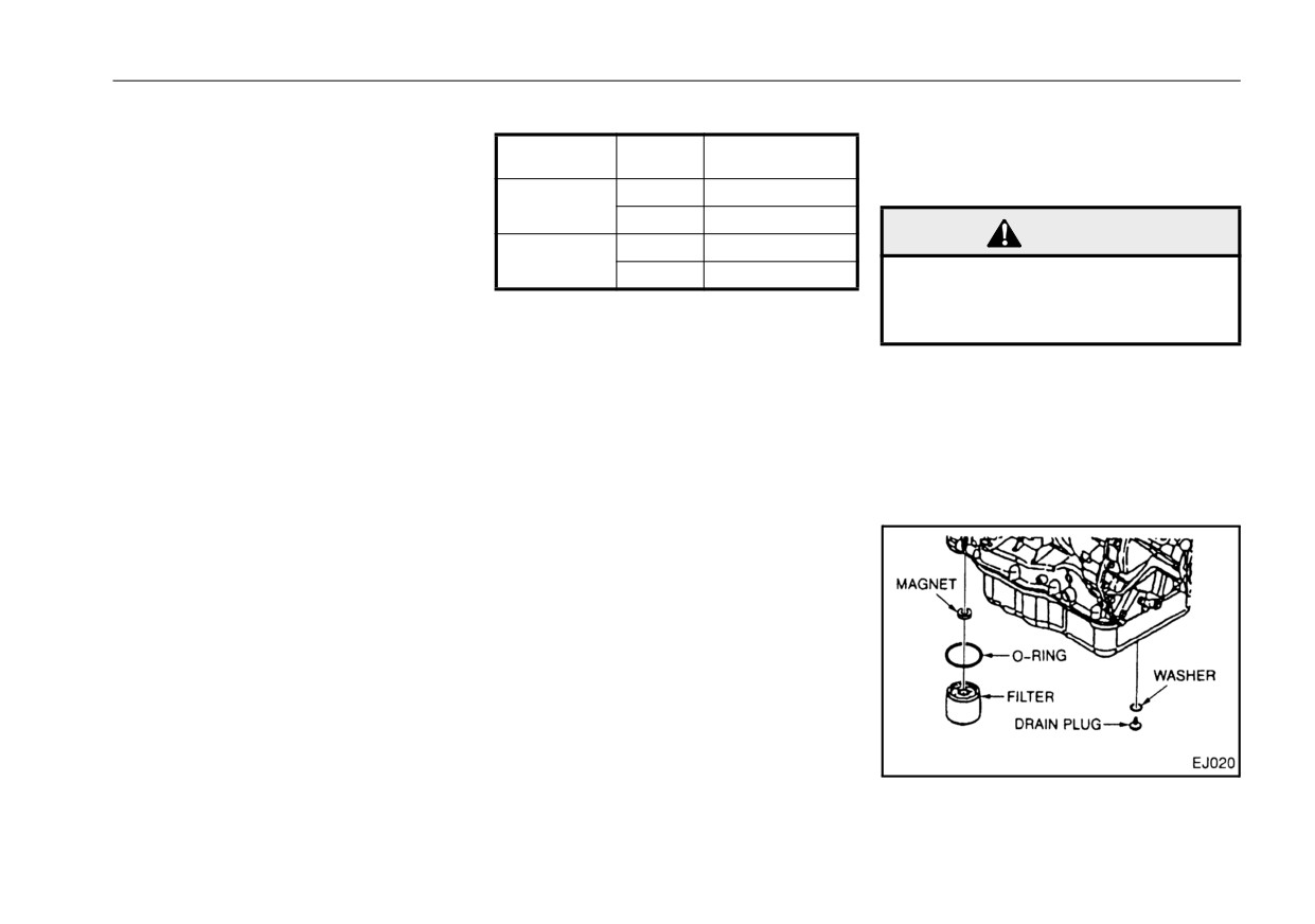
z The drain plug contains a mag-
sion
fluid
listed
in
the
net. Remove any iron filings on
"RECOMMENDED
LUBRI-
the plug before reinstalling the
CANTS"on page 13-5.
plug.
3.Fill the transmission with fresh oil
through the filler plug hole located
on the side of the transmission.
11 - 57

-------------------------------------------------------------------------------------------------------------------------------------------------------------

VEHICLE SERVICE AND MAINTENANCE
2.Remove the drain plug from the oil
Allison 3000 series
CAUTION
pan and allow the fluid to drain into
A disassembled type of filter is used
a suitable container.
z Turning the filter more than
and incorporated in the oil pan.
3.Using a filter wrench, remove the
ONE FULL TURN after gasket
contact will damage the filter.
control-main filter by rotating it
counterclockwise.
4.Remove the magnet from the filter
10.Reinstall the drain plug and seal-
attachment tube or from the top of
ing washer.
the filter element.
Tightening torque:
22 to 30 ft·lbf (30 to 40 N·m) (3.1
5.Clean any metal debris from the
to 4.1 kgf·m)
magnet. Report any metal pieces
11.After refill, check the fluid level
larger than dust to your mainte-
and add the proper fluid, if neces-
nance personnel.
sary.
6.Reinstall the magnet onto the filter
For the fluid check procedure,
1.Clean the periphery of the filter
attachment tube.
refer to "To check the automatic
cover to prevent dust from entering
7.Lubricate the O-ring on the control-
transmission fluid level
(Allison
at the time of removal of the filter.
main filter with transmission fluid.
1000, 2200 and 2500 series)"on
2.Remove the mounting bolts of the
8.Install, by hand, the control-main
page 11-52.
filter cover and pull out the cover
filter until the O-ring on the control-
12.Start the engine. Check the filter
and filter downward.
main filter touches the converter
and seal for leaks.
3.Replace the filter, O-ring and seal
housing.
with new ones and install to the
9.Turn the filter ONE FULL TURN
cover. When installing, apply a
ONLY by hand, after O-ring con-
light coating of clean oil to the
tact.
entire perimeter of O-ring and seal.
4. Install the cover and filter com-
bined in one unit into the transmis-
sion body.
11 - 58

-------------------------------------------------------------------------------------------------------------------------------------------------------------

VEHICLE SERVICE AND MAINTENANCE
Tightening torque:
DIFFERENTIAL GEAR OIL
CAUTION
37.6 to 45.0 ft·lbf (51 to 61 N·m)
(5.2 to 6.2 kgf·m)
Gear oil
z Before removing the differen-
5.After replacement, be sure to refill
tial filler plug, clean the plug
Inspect the vehicle daily for differen-
and surrounding area to pre-
fluid. After refilling, check the fluid
tial oil leakage. If there is any evi-
vent dirt and debris from enter-
level.
dence of leakage, locate and correct
ing filler hole.
the cause. Check oil level and, if low,
add oil.
WARNING
z Check and/or change the dif-
ferential gear oil only after the
rear axle cools to avoid possi-
ble burn injuries.
To check the differential gear oil
level
1.Remove the filler plug and visually
check the oil level. The level
2.Add oil, if necessary.
should reach the bottom of the
3.Replace the gasket of the filler
filler plug hole.
plug with a new one. Reinsert the
plug and tighten the plug.
Tightening torque:
95 to 108 ft·lbf (128 to 147 N·m)
(13 to 15 kgf·m)
11 - 59

-------------------------------------------------------------------------------------------------------------------------------------------------------------

VEHICLE SERVICE AND MAINTENANCE
Oil change
Tightening torque:
STEERING SYSTEM
95 to 108 ft·lbf (128 to 147 N·m)
(13 to 15 kgf·m)
Wheel free play
WARNING
NOTE:
To check for free-play, start and idle
z Check and/or change the dif-
z The drain plug contains a mag-
the engine. Set the front wheels to
ferential gear oil only after the
net. Remove any iron filings on
the straight-ahead position and
rear axle cools to avoid possi-
the plug before reinserting the
lightly rotate the steering wheel to
ble burn injuries.
plug.
the right and left until the front
wheels move. Steering wheel play
3.Fill the differential with fresh oil.
1.Place a container under the differ-
on the circumference of the steering
Check the oil level. Add oil until the
ential drain plug. Remove the drain
wheel should be 0.39 to 1.57 inches
level reaches the bottom of the
plug and drain the oil completely.
(10 to 40 mm) for UD1800, UD2000
filler plug hole.
and UD2300 or 1.18 to 1.97 inches
(30 to
50 mm) for UD2600 and
Oil refill capacity (Approximately)
UD3300. If the play exceeds 1.57
inches
(40 mm) for UD1800,
US measure
Liters
UD2000 and UD2300 or 1.97 inches
UD1800,
(50 mm) for UD2600 and UD3300,
UD2000 and
6.9 qt
6.5
have it corrected by an authorized
UD2300LP
UD Trucks dealer or other qualified
service facility.
UD2300HD
9.5 qt
9
UD2600 and
13.8 qt
13
UD3300
2.After draining, replace the gasket
of the drain plug with a new one.
Install the plug and tighten the
plug.
11 - 60

-------------------------------------------------------------------------------------------------------------------------------------------------------------

VEHICLE SERVICE AND MAINTENANCE
Steering fluid level
CAUTION
If the steering fluid is low or contami-
nated, the power steering may not
z Do not allow dirt or debris to
operate normally which could
enter the fluid reservoir when
adversely affect steering control. If
open. Always clean the fluid
the fluid level is low, check the steer-
reservoir and cap before
ing system for leaks and correct the
removing the cap.
condition before operating the vehi-
z Check for proper fluid level
cle. If the fluid is contaminated, have
before engine start.
it replaced by an authorized UD
Trucks dealer or qualified service
To inspect the steering fluid level
facility.
1.Visually inspect the steering sys-
WARNING
tem for fluid leaks.
z
Do not operate your vehicle
2.The fluid level should be between
with excessive steering wheel
WARNING
the HIGH and LOW lines. If the
free-play. If free-play exists,
fluid level is below the LOW line,
z To avoid possible burn injury,
have the vehicle thoroughly
allow the steering system to
add steering fluid to the HIGH line.
inspected by an authorized UD
cool before checking or chang-
Trucks dealer or qualified ser-
ing the steering fluid.
vice facility.
z Do not operate the vehicle
when the steering fluid is low
or contaminated.
11 - 61

-------------------------------------------------------------------------------------------------------------------------------------------------------------

VEHICLE SERVICE AND MAINTENANCE
Steering fluid and filter change
SERVICE BRAKE SYSTEM
WARNING
Have the steering fluid and filter
Brake fluid level check
changed by an authorized UD
z
Brake fluid loss may indicate a
Trucks dealer or other qualified
Maintain the fluid level in the reser-
leak in the brake system. Have
steering system repair facility.
Use
voir between the HIGH and LOW
the brake system checked
immediately by an authorized
only DEXRON®II or higher fluid.
marks on the brake fluid reservoir. If
UD Trucks dealer or other
the fluid level is below the LOW mark
qualified brake repair facility.
then add brake fluid.
z
To avoid fire hazard, do not
allow brake fluid to contact the
hot parts of the exhaust sys-
tem.
z
To avoid possible burn injury,
allow the engine and brake
system to cool before check-
ing or changing brake fluid.
z
If the brake (and clutch) fluid is
accidentally ingested, force
the person to vomit and secure
medical help immediately. If
the brake
(and clutch) fluid
gets in an eye, flood the eye
with lots of water and get med-
ical attention immediately.
11 - 62

-------------------------------------------------------------------------------------------------------------------------------------------------------------

VEHICLE SERVICE AND MAINTENANCE
Brake fluid change
Draining air reservoir
CAUTION
Have the brake fluid changed by an
To drain accumulated water from
z
Remove any dirt accumulation
authorized UD Trucks dealer or
the air reservoir
from the brake fluid reservoir
other qualified brake system repair
1.Open the drain cocks.
cap and surrounding area
facility. Use only DOT 3 fluid from a
before removing the reservoir
sealed container.
cap. Do not allow dirt, debris,
water or other foreign materi-
NOTE:
als to enter the reservoir while
z After the brake fluid has been
it is open.
changed, operate the service
z
Use only approved DOT 3 fluid
brakes several times to assure
from a sealed container.
proper operation.
z
Do not add brake fluid above
the HIGH mark.
z
Do not allow brake fluid to con-
CAUTION
tact the painted surfaces of
your vehicle. Brake fluid con-
z
Do not expose the brake fluid
tact may result in paint dam-
2.Allow the water to drain.
to moisture when checking,
age.
3.After draining, release
the
drain
adding or changing the brake
z
Remove the reservoir strainer
cock rings and close
the
drain
fluid. Brake fluid absorbs
and clean any foreign matter
cocks.
from it. If the reservoir con-
moisture. When it does, its
tains sediment, have the reser-
boiling point drops which can
voir inspected and cleaned by
cause vapor lock and corro-
WARNING
an authorized UD Trucks
sion of brake system compo-
dealer or other qualified brake
nents.
z Do not drive vehicle unless
repair facility.
z
Do not add brake fluid which
accumulated water has been
has been exposed to moisture
drained. If not, water could get
to the system. Use fresh DOT 3
into
brake system and
fluid from a sealed container
adversely effect brake func-
only.
tion.
11 - 63

-------------------------------------------------------------------------------------------------------------------------------------------------------------

VEHICLE SERVICE AND MAINTENANCE
Air dryer
have the air dryer repaired by an
CAUTION
authorized UD Trucks dealer or
z
As vehicles are equipped with
other qualified brake system repair
an air dryer, water will nor-
facility.
mally not drain from the air
If the drained liquid contains a large
reservoir when the drain cock
amount of oil, additionally have the
is opened. However, a small
air compressor checked.
amount of water may drain out
under humid conditions. If a
large amount of water is
WARNING
drained, the air dryer may not
To avoid brake failure:
be functioning properly. Check
z
Visually check to be sure that
the air dryer.
water or air is discharged from
bottom drain port.
Visually check to be sure that water
z
Replace desiccant, filters and
drains from the drain port of the air
gasket annually.
dryer. Water will drain when the air
z
Do not allow drain port to clog
pressure governor stops pressuriza-
with foreign material.
tion. The governor stops pressuriza-
tion when the air pressure in the
reservoir reaches the upper level of
the normal operating pressure
range. When the sound of air sup-
plied to the reservoir can no longer
be heard, or when the sound of the
engine changes, this condition has
been reached.
If no water drains from the air dryer,
drain the water from the air reservoir.
If a large amount of water is drained,
11 - 64

-------------------------------------------------------------------------------------------------------------------------------------------------------------

VEHICLE SERVICE AND MAINTENANCE
CLUTCH
Adjusting clutch pedal free play
To adjust the outer lever assembly
After adjusting the clutch master cyl-
To adjust the clutch master cylinder
Clutch pedal free play
inder, adjust the clutch booster outer
First adjust the master cylinder
lever assembly located at the left
To check clutch pedal free play,
located on the clutch pedal.
side of the transmission.
depress the clutch pedal by hand
1.Loosen the lock nut on the push
1.Remove the return spring.
until resistance is felt. The play, the
rod.
2.Loosen the push rod lock nut.
distance from the point where the
2.Turn the push rod until it touches
3.Adjust the play of the outer lever to
clutch pedal normally rests and
the piston and there is no play.
0.177 to 0.217 inches (approx. 4.5
where resistance is felt should be
Under this condition, return the
to 5.5 mm) by turning the push rod.
1.18 to 1.97 inches (30 to 50 mm). If
push rod 4/5 turn and make sure
the play is less than 1.18 inches (30
the free play is approximately 0.04
mm) or more than 1.97 inches (50
inches (1 mm).
mm), then adjust the clutch pedal
3.Tighten the lock nut while holding
free play.
the push rod stationary with a
wrench.
MLS63
11 - 65

-------------------------------------------------------------------------------------------------------------------------------------------------------------

VEHICLE SERVICE AND MAINTENANCE
Checking clutch fluid
MPS63
MLS63
4.Tighten the lock nut.
NOTE:
5.Reinstall the return spring.
z DOT 3 brake fluid is used as
clutch fluid. Be sure to handle it
6.Check clutch disc wear with the
carefully. (Refer to "Brake fluid
wear indicator installed near the
level check"on page 11-62.)
left side clutch booster. Clutch disc
wear is within acceptable limits
The clutch fluid level should be
when the pointer at the wear indi-
between the HIGH and LOW marks
cator is between MIN and SET. If
on the fluid reservoir located behind
the pointer goes past MIN, have
the front lid. If the fluid level is low,
the clutch disc replaced by an
add DOT 3 brake fluid until the level
MPS63
authorized UD Trucks dealer or
is between the HIGH and LOW
qualified service facility.
marks. Also check the clutch fluid for
contamination. If the fluid appears
contaminated, have the clutch fluid
changed.
11 - 66

-------------------------------------------------------------------------------------------------------------------------------------------------------------

VEHICLE SERVICE AND MAINTENANCE
Changing clutch fluid
SUSPENSION
WARNING
Have the clutch fluid changed by an
Leaf spring
z
To avoid fire hazard, do not
authorized UD Trucks dealer or
allow clutch fluid to contact
other qualified brake system repair
Check the leaf spring for damage,
the hot parts of the exhaust
facility. Use only DOT 3 fluid from a
displacement of leaves or loose-
system.
sealed container.
ness. If loose, align the leaves and
tighten bolts and nuts to the speci-
fied torque. Periodically have the U-
CAUTION
bolt nut retightened by an authorized
UD Trucks dealer or qualified service
z
Do not expose the clutch fluid
facility.
to moisture when checking,
adding or changing the clutch
Tightening torque:
fluid. Clutch fluid absorbs
Front spring U-bolt nut
moisture. When it does, its
UD1800, UD2000 and UD2300
boiling point drops which can
174 - 203 ft·lbf
cause corrosion of clutch sys-
(235 - 275 N·m) (24 - 28 kgf·m)
tem components.
UD2600 and UD3300
z
Do not add clutch fluid which
362 - 398 ft·lbf
has been exposed to moisture
(490 - 539 N·m) (50 - 55 kgf·m)
to the system. Use fresh DOT 3
fluid from a sealed container
Rear spring U-bolt nut
only.
UD1800, UD2000 and UD2300
z
Do not allow clutch fluid to
195 - 239 ft·lbf
contact the painted surfaces of
(265 - 324 N·m) (27 - 33 kgf·m)
your vehicle. Clutch fluid con-
UD2600 and UD3300
tact may result in paint dam-
362 - 398 ft·lbf
age.
(490 - 539 N·m) (50 - 55 kgf·m)
11 - 67

-------------------------------------------------------------------------------------------------------------------------------------------------------------

VEHICLE SERVICE AND MAINTENANCE
Air spring
WINDSHIELD WASHER FLUID
2.If it is low, add more washer fluid
via reservoir cap opening
Check the air bellows for damage,
air leakage, looseness and leveling
valve for proper functioning.
WARNING
Periodically have the U-bolt nut
retightened by an authorized UD
z Do not use cooling system
Trucks dealer or qualified service
solution in the windshield
facility.
washer
reservoir.
When
sprayed on the windshield,
Tightening torque:
cooling system solution can
U- bolt nut
significantly diminish visibility.
406 - 455 ft·lbf
(550 - 617 N·m) (56 - 63 kgf·m)
Open the front lid, and check the
NOTE:
fluid level in the windshield washer
z Do not overfill the windshield
Shock absorber
reservoir daily. If low, add an appro-
washer reservoir.
Check the shock absorber for proper
priate washer fluid solution. Also,
installation, damage or leakage. If
check that fluid is properly sprayed
leakage is present, have the shock
onto the windshield.
absorber checked or replaced by an
In cold weather, use a windshield
authorized UD Trucks dealer or qual-
washer anti-freeze with water at the
ified service facility.
proper mixture ratio. Follow the anti-
freeze manufacturer’s instructions
for the mixture ratio.
Replenishing washer fluid
The windshield washer reservoir
located behind the front lid.
1.Open the front lid, and check the
washer reservoir fluid level.
11 - 68

-------------------------------------------------------------------------------------------------------------------------------------------------------------

VEHICLE SERVICE AND MAINTENANCE
OUTSIDE MIRRORS
Adjusting outside mirrors
To check the mirror heater
1.Set the stay by aligning it with the
(Optional)
matching mark.
2.Adjusting the outside mirror posi-
tion.
z Since the plain mirror on the upper
side cannot be adjusted using the
mirror alone, adjust it by moving
the mirror housing. The convex
mirror on the lower side can be
adjusted using the mirror alone.
On a vehicle equipped with a mirror
heater, check the following points.
z Check the heater harness for slack
and twist.
CAUTION
z Do not yank the heater har-
ness by hand or hang on the
Check the outside mirrors daily for
z For vehicles equipped with power
heater harness. The heater
damage, position and visibility. Also
mirror, refer to the "Power mirror
harness may be broken.
check that the mirror mounting bolts
switch (Optional)"on page 7-68.
are properly tightened.
11 - 69

-------------------------------------------------------------------------------------------------------------------------------------------------------------

VEHICLE SERVICE AND MAINTENANCE
EMISSIONS CONTROL
Exhaust Aftertreatment System
Regular maintenance for the DPF
Maintenance
SYSTEMS
z
The muffler that is equipped with
The vehicle must be taken to an
authorized UD Trucks dealer to
the DPF needs to be cleaned regu-
To maintain efficient emissions con-
remove the ash from the Aftertreat-
larly to maintain its performance
trol systems operation, have the
ment Diesel Particulate Filter and
(either every
155,000 miles
emission control system mainte-
clean the Aftertreatment Hydrocar-
[250,000 km] or 4,500 hours). This
nance in the VEHICLE SERVICE
bon Doser.
is because unburnable ash will
AND MAINTENANCE performed at
Emissions Maintenance
accumulate in the filter during
the intervals indicated.
Emissions Maintenance Interval
-
regeneration; otherwise, the soot
EPA / CARB defines this as the
accumulated in the DPF can be
CAUTION
adjustment, cleaning, repair, or
burned to regenerate the filter.
z
Do not modify, alter, discon-
replacement shall be recommended
z
For details on the cleaning infor-
nect or remove any part of the
at intervals no less than described
mation about the muffler that is
vehicle which could affect,
below.
equipped with the DPF, contact
Injector tips
(cleaning only), crank-
directly or indirectly, vehicle
your nearest UD trucks dealer.
emissions.
case ventilation
z
The DPF ash level gauge that is
z
Do not operate your vehicle if
valve, EGR filters and coolers:
displayed on the multi-display
you notice engine misfire, a
Medium Heavy Duty:
monitor indicates the amount of
significant loss of performance
Miles: 50,000
ash accumulation.
or other improper operation.
Hours: 1500
Consult your UD Trucks dealer
or other qualified service facil-
Injectors, Turbocharger, ECM, sen-
ity for service.
sors, actuators, EGR components
(except filter and coolers), Aftertreat-
ment DPF plus related components,
this includes ash cleaning
Medium Heavy Duty:
Miles: 150,000
Hours: 4500
11 - 70

-------------------------------------------------------------------------------------------------------------------------------------------------------------

VEHICLE SERVICE AND MAINTENANCE
CAUTION
z The muffler that is equipped
with the DPF for the PM reduc-
tion device needs to be
cleaned regularly (either every
155,000 miles [250,000 km] or
4,500 hours) even if the DPF
ash level gauge does not reach
“H”.
If not, poor fuel economy and
engine output decrease may
DPF ash level gauge
DPF maintenance warning
occur.
z
The DPF ash level gauge indicates
the accumulation level of the ash
NOTE:
in the filter.
z
Ash is mainly generated from
z
For details on how to display the
the elements included in engine
meter, refer to the
“Multi-display
oil additives. Always use the
monitor” section in “INSTRUMENT
specified engine oil to minimize
AND CONTROLS”.
ash generation.
z
When the level reaches “H”, it indi-
z
The soot collected in the DPF
cates that the filter should be
that is built in the muffler for the
cleaned. The system simultane-
PM reduction device is burned
ously indicates the DPF mainte-
to be regenerated. However, ash
nance warning, warning message
is unburnable during regenera-
and comment to alert the driver of
tion and accumulates in the fil-
cleaning the DPF.
ter. Thus, the filter must be
cleaned regularly.
To keep the DPF efficiency, it
recommend that the manual
11 - 71

-------------------------------------------------------------------------------------------------------------------------------------------------------------

VEHICLE SERVICE AND MAINTENANCE
forced regeneration is per-
formed once a year even if the
DPF soot level indicates. For
details on the manual forced
regeneration, refer to the "DPF
SYSTEM"on page 7-69
z
The accumulation level shown
in the DPF ash level gauge is
calculated by the control unit
using the fuel consumption
data. Therefore, the gauge indi-
cation may differ from the filter
cleaning interval of the muffler
that is equipped with the filter
for the PM reduction device
(either every
155,000 miles
[250,000 km] or 4,500 hours).
Use the DPF ash level gauge
indication as a reference.
11 - 72

-------------------------------------------------------------------------------------------------------------------------------------------------------------

VEHICLE SERVICE AND MAINTENANCE
NOISE CONTROL SYSTEM
Tampering with Noise Control
device or element of design has
System Prohibited
been removed or rendered inopera-
Federal law prohibits the following
tive by any person.
To assure noise control system
acts or the causing thereof:
Among those acts presumed to con-
integrity, the maintenance services
stitute tampering are the acts listed
shown in the following chart must be
(1) The removal or rendering inoper-
below.
performed at the intervals indicated.
ative by any person other than for
When inspecting the exhaust system
purposes of maintenance, repair, or
confirm that all components are
replacement, of any device or ele-
WARNING
intact and securely fitted. Also check
ment of design incorporated into any
all exhaust system components for
z To avoid serious injury from
new vehicle for the purpose of noise
holes, leaks and corrosion. Do not
hot engine and exhaust sys-
control prior to its sale or delivery to
perform any prohibited act to the
tem, perform maintenance
the ultimate purchaser or while it is in
noise control system as described in
after engine has cooled.
use, or
the following chart.
(2) the use of the vehicle after such
Control System
Prohibited Acts
Removal or rendering inoperative air cleaner,
Air Intake System
intake resonator or intake duct, and piping.
Removal of cab shields or acoustical insulation.
Acoustical Shielding
Removal of engine enclosures.
Removal or rendering inoperative fan clutch.
Cooling System
Removal of fan shrouds or radiator side shields.
Removal or rendering engine speed governor
Engine and Drive Line System
inoperative so as to allow engine speed to exceed
manufacturer specifications.
Removal or rendering inoperative exhaust system
Exhaust System
components including muffler, pipe shield or pip-
ing.
11 - 73

-------------------------------------------------------------------------------------------------------------------------------------------------------------

VEHICLE SERVICE AND MAINTENANCE
Noise Control System Maintenance
may be equipped with the following
maintenance at the intervals shown
Schedule
items.
in the following maintenance chart.
In order to comply with federal noise
To avoid or minimize the degradation
regulation, the UD Trucks vehicle
of noise emission level, it is essential
to perform proper inspection and
Abbreviations:
A = Check and adjust if
T = Tighten to specified torque
R = Replace or change
necessary
First
Every
Miles x 1,000
3
6
9
10
12
15
18
20
24
30
36
50
72
Months
Items
Kilometersx1,000
5
10
15
16
20
25
30
32
40
48
60
80
120
(every)
High idling speed
A
12
Cooling fan
A
12
Air intake system hose and clamps
A
4
Air cleaner element
R
12
Exhaust manifolds mounting nuts
T
12
Muffler with catalyst and exhaust pipe clamps
A
6
Splash shields, under hood insulator
A
12
Maintenance of noise emission
Splash shield, under hood
Cooling fan
control system
insulation
z Check the cooling fan for damage,
Check shields and under hood insu-
and replace it when damaged.
lation for damage or looseness.
z Check the cooling fan mounting
Repair, replace or clean if necessary.
bolts for looseness, and tighten
them if necessary.
11 - 74

-------------------------------------------------------------------------------------------------------------------------------------------------------------

VEHICLE SERVICE AND MAINTENANCE
Intake system
changed from standard position as
BATTERY
z Check the intake system compo-
originally received.
nents such as ducts, hoses, reso-
To avoid abnormal changes in vehi-
Your UD Trucks vehicle is equipped
cle sound level, maintenance is nec-
nator air cleaner, intake manifold,
with a maintenance-free battery at
essary at the intervals shown in the
clamps and fasteners for damage.
the factory.
maintenance schedules, and record
Replace if necessary. Check to be
Below are the specifications for the
on the inspection verification form
sure that hose clamps and fasten-
two 12 volt batteries installed at the
provided. Please consult an autho-
factory. Their reserved capacity (RC)
ers are tight.
rized UD Trucks dealer.
and cold cranking amperes (CCA)
z Check to be sure that the air
are rated at 159 minutes and 622
cleaner dust cover is installed
amperes.
securely.
z Check the rubber gasket in the
dust cover for deterioration.
Replace if necessary.
Exhaust system
Check the complete exhaust system.
Check for damage, missing or mis-
positioned parts, loose connections,
open seams, holes, loose fasteners,
or deformed or plugged outlets.
Replace or tighten if necessary.
Inspect for leaks at various joint con-
nections and tighten clamp. Make
visual inspection for crack or holes in
DPF cleaner and tail pipe. Always
replace with UD Trucks recom-
mended parts. Tail pipe elbow or off-
set tail pipe orientation must not be
11 - 75

-------------------------------------------------------------------------------------------------------------------------------------------------------------

VEHICLE SERVICE AND MAINTENANCE
Battery electrolyte level
W
6.81 in (173 mm)
L
12.05 in (306 mm)
H
8.03 in (204 mm)
DANGER
Positive (+) terminal:
Batteries produce explosive
0.756 - 0.768 in
gases. To minimize risk of seri-
(19.2 - 19.5 mm)
Taper
d
ous injury or death:
1/9
Negative (-) terminal:
z
Keep sparks and open flame
0.693 - 0.705 in
away from the batteries. Never
(17.6 - 17.9 mm)
smoke when working on or
h
0.67 - 0.79 in (17 - 20 mm)
around the batteries.
To add distilled water
z
Make sure that adequate venti-
1.Remove the cell plugs using a suit-
lation is provided when work-
able tool.
ing on or around the battery in
2.Add distilled water up to the upper
an enclosed area.
level.
z
Do not permit metal tools to
3.Tighten cell plugs.
simultaneously contact the
positive battery terminal and
any other metal on either vehi-
cle at the same time.
z
Always wear eye protection
when working near batteries.
The battery electrolyte should be
maintained between the upper and
lower levels on the case. If low, add
distilled water to the specified level
and charge the battery for at least 30
minutes with the engine idling.
11 - 76


Content      ..     11      12      13      14     ..