Takeuchi Mini excavator TB225 (No.122500005~). Operator's Manual (2019) - page 6
MAINTENANCE
EVERY 1000 HOURS
INSPECTING AND ADJUSTING THE
ENGINE VALVE CLEARANCE
This operation requires experience. Ask your
service dealer for it.
REPLACING THE PILOT LINE FILTER
Refer to “Replacing the pilot line filter” on
page 5-34.
5-46
MAINTENANCE
EVERY 1500 HOURS
EVERY 1500 HOURS
INSPECTING AND CLEANING THE
ENGINE FUEL INJECTORS
This operation requires experience. Ask your
sales or service dealer for it.
INSPECTING THE CRANKCASE
BREATHER SYSTEM
This operation requires experience. Ask your
sales or service dealer for it.
5-47
MAINTENANCE
EVERY 2000 HOURS
Then, slowly loosen the radiator cap
EVERY 2000 HOURS
and the drain plug to remove them.
CLEANING THE ENGINE COOLING
SYSTEM
When cleaning, if the temperature of the
coolant is low, the thermostat will be closed
Replace the coolant after the two-year
and the coolant will not circulate in the
operation even if the running time is less than
radiator. Heat the coolant water to at least
2000 hours.
90°C (194°F) before cleaning.
1. Open the engine hood.
• Stop the engine and allow the machine
to cool down before performing
maintenance.
· The engine, muffler, radiator and many
other parts of the machine are hot
immediately after the engine is
stopped. Touching these parts will
cause burns.
· The engine coolant is also hot and
under high pressure immediately after
the engine is stopped. Be careful
when loosening the caps or plugs.
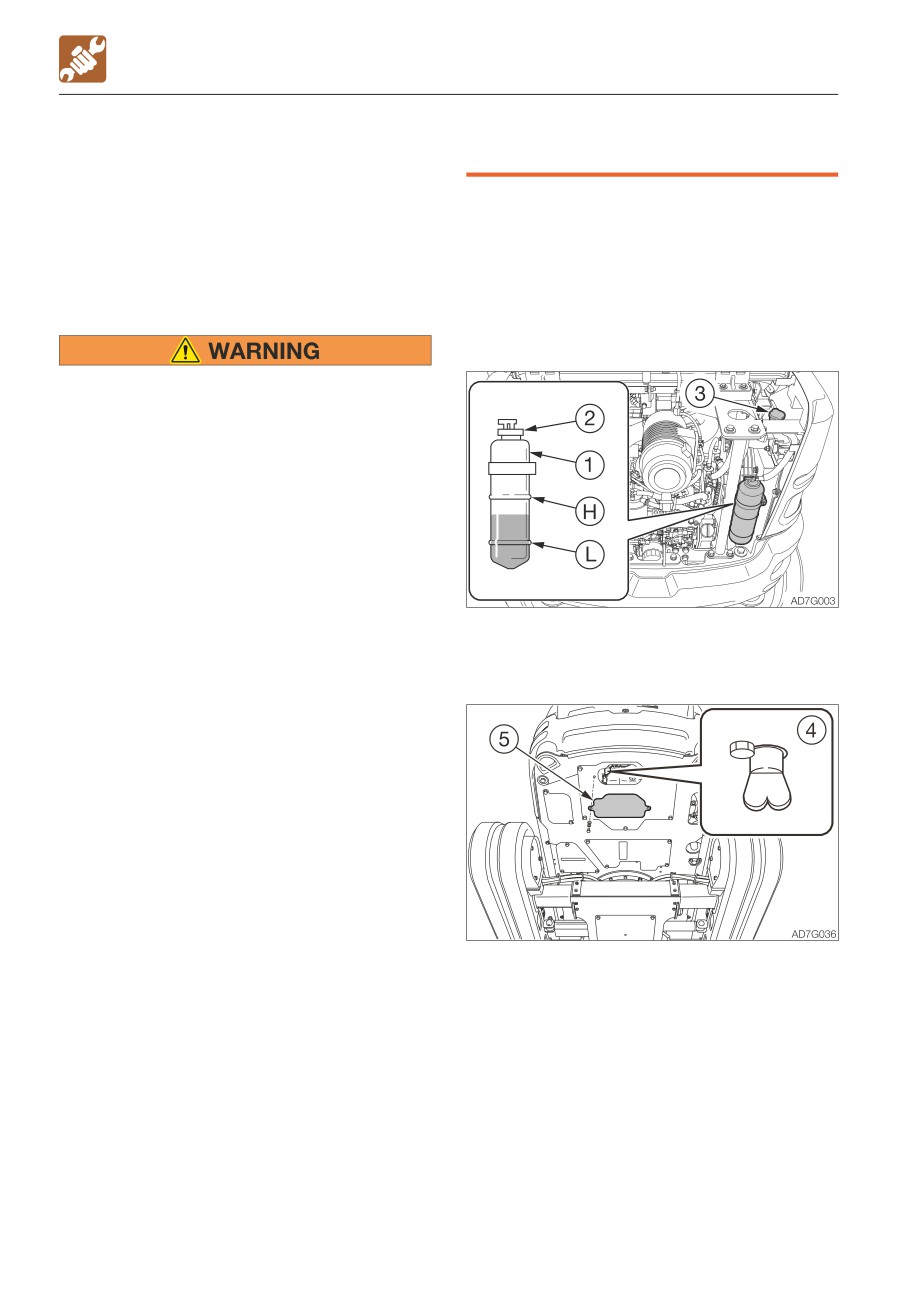
2. Gradually loosen the radiator cap (3) to
Working on the machine under these
release the internal pressure, and then
conditions could result in burns or
remove the cap.
injuries due to the hot coolant spurting
out.
• If maintenance must be performed with
the engine running, always work as a
two person team communicating each
other.
· One person must sit in the operator’s
seat so that he/she can immediately
stop the engine when necessary. He/
she must take care not to touch the
lever or pedal unless necessary.
· The one who performs maintenance
must make sure to keep his/her body
3. Loosen the bolts and open the cover (5).
or clothing away from the moving part
4. Place a pan for catching the waste coolant
of the machine.
under the drain plug (4), and then loosen
• Standing at the back of the machine
the drain plug (4) to drain the coolant.
while the engine is running is extremely
5. Tighten the drain plug (4).
dangerous, as the machine could move
6. Add tap water to the radiator through the
suddenly. Never stand at the back of the
coolant fill port up to the top of the port.
machine while the engine is running.
Take time and slowly add water, so that no
• Do not remove the radiator cap or the
air enters the radiator.
drain plug when the cooling water is
7. Close the radiator cap (3).
hot. Stop the engine and wait until the
engine and the cooling water cool.
5-48
MAINTENANCE
EVERY 2000 HOURS
8. Start the engine and run it at a speed
LAPPING THE ENGINE VALVE SEATS
slightly above low idling. Raise the water
temperature to at least 90°C (194°F), and
This operation requires experience. Ask your
then run the engine for about 10 minutes
sales or service dealer for it.
with the thermostat open.
9. Stop the engine, wait until the cooling water
temperature becomes lower, and then
remove the drain plug (4) to drain the water.
10. After draining, clean the cooling system
using a cleaning agent. When using the
cleaning agent, follow the instructions
included with the agent.
11. Repeat the steps 4 to 8 to rinse the
cooling system.
12. Tighten the drain plug (4).
13. Take time and slowly add the new
coolant (mixture of antifreeze and tap
water) to the radiator through the fill port
until it is full.
14. Close the radiator cap (3).
15. Warm up the engine. Use the meters to
check that there are no irregularities in
the cooling system at this time.
16. Increase the water temperature to at
least 90°C (194°F). Then, run the engine
for about 10 minutes with the thermostat
kept open.
17. Stop the engine, wait until the cooling
water temperature becomes lower, and
then check the level of coolant in the
radiator.
If necessary, add cooling water until the
radiator is full.
18. Close the radiator cap (3).
19. Clean the interior of the reserve tank (1),
and then add coolant to the upper limit
(H).
20. When the coolant has been replaced,
inspect the coolant level once again after
operating the machine.
Once the machine is operated, the
coolant is distributed throughout the
entire system, resulting in the lower
coolant level.
Replenish the cooling water that has
been used.
5-49
MAINTENANCE
EVERY 4000 HOURS
EVERY 4000 HOURS
REPLACING THE HYDRAULIC OIL AND
CLEANING THE SUCTION STRAINER
• Stop the engine and allow the machine
to cool down before performing
maintenance.
· The engine and the hydraulic system
and many other parts of the machine
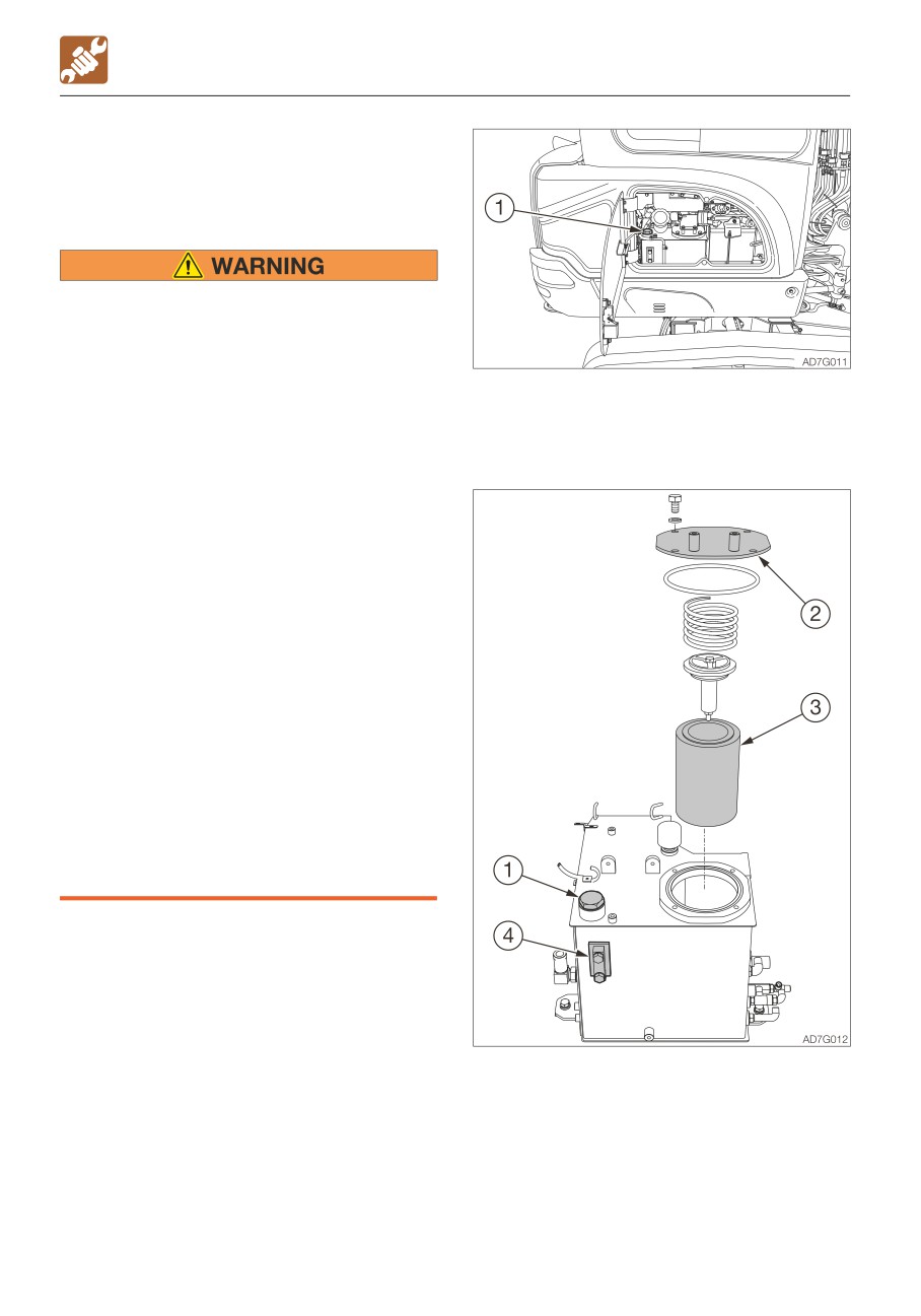
3. Open the side cover.
are hot immediately after the engine is
4. Slowly loosen the air bleeding plug (1) to
stopped. Touching these parts will
relieve the internal pressure, and then
cause burns.
remove the plug.
· The hydraulic oil is also hot and under
high pressure immediately after the
engine is stopped.
Be careful when loosening the caps or
plugs. Working on the machine under
these conditions could result in burns
or injuries due to the hot oil spurting
out.
• Oil may spurt out if caps or filters are
removed or pipes are disconnected
before releasing the pressure in the
hydraulic system.
· Gradually loosen the vent plug to
relieve tank pressure.
· When removing plugs or screws, or
when disconnecting hoses, stand to
the side and loosen them slowly to
gradually release the internal pressure
before removing.
1. Set the machine to the hydraulic oil level
inspection posture.
Refer to “Inspecting the hydraulic oil tank
level and replenishing” on page 5-21.
2. Raise the safety lock lever to the locked
position.
5. Loosen the bolts to take out the flange (2).
6. Remove the return filter (3).
5-50
MAINTENANCE
EVERY 4000 HOURS
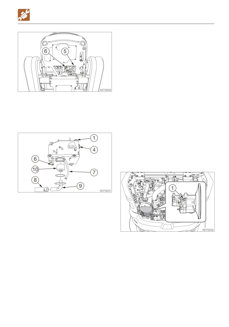
20. Add hydraulic oil from the hole of plug (1)
up to the level between the upper limit
(H) and the lower limit (L) in the sight
gauge (4).
21. Tighten the plug (1).
22. Bleed air from the hydraulic oil circuit
following “Bleeding air” below.
23. Set the machine to the hydraulic oil level
inspection posture and inspect the oil
level when the oil temperature drops.
Refer to “Inspecting the hydraulic oil tank
7. Loosen the bolts and remove the under
level and replenishing” on page 5-21.
cover (5).
24. Install the under cover (5).
8. Place a pan for catching the waste oil
under the drain plug (6).
Bleeding air
9. Loosen the drain plug (6) and drain the
hydraulic oil.
IMPORTANT: After replacing the hydraulic
oil or hydraulic devices, or after
performing maintenance of the hydraulic
devices, bleed air from the hydraulic
circuits and hydraulic devices. Failure to
do so may damage the hydraulic devices.
• Hydraulic pump
10. Loosen the hose bands and remove the
hoses (7) and (8).
11. Loosen the bolts and remove the flange
(9).
12. Remove the suction strainer (10) and
clean it.
13. Clean the inside of the hydraulic oil tank.
14. Replace the air breather (if equipped).
1. Open the engine hood.
Refer to “Replacing the air breather” on
2. Loosen the vent plug (1) on the hydraulic
page 5-45.
pump.
15. Install the suction strainer (10) to the
3. Once hydraulic oil overflows from the vent
flange (9).
plug hole (1), tighten the vent plug (1).
16. Reinstall the flange (9) and the hoses (7)
and (8) on their original positions.
17. Install a new return filter to the flange (2).
18. Reinstall the flange (2) to their original
positions.
19. Tighten the drain plug (6).
5-51
MAINTENANCE
EVERY 4000 HOURS
• Cylinders
Boom
1. Start the engine, let it run at a low-idling
speed for 10 minutes.
2. Maintain the engine at low idle, then
extend and retract each cylinder 4 or 5
times, without let them reach the stroke
end.
3. Run the engine at high speed, then extend
and retract each cylinder 4 or 5 times,
without let them reach the stroke end.
4. Set the engine back to a low idle, then
extend and contract all the cylinders 4 or 5
times to the stroke ends.
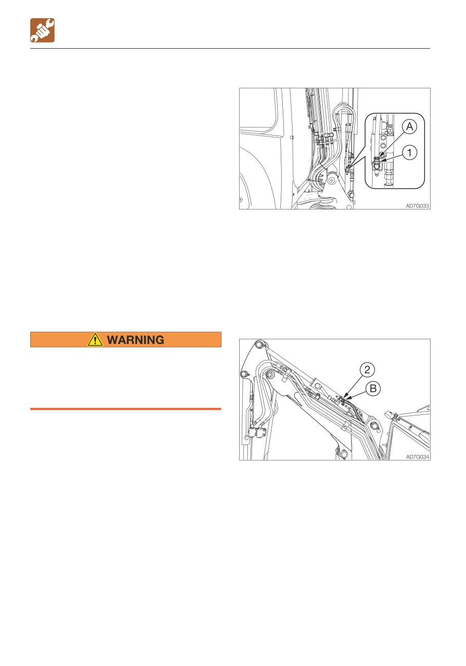
4. Hold the hose fitting (A) in place with a
• Emergency shut-off valve (If equipped)
wrench and slowly loosen the hose nut (1).
This operation is dangerous and requires
5. Slowly move the boom in the “Boom
experience. Ask your sales or service
lower” direction a little until there are no
dealer for help.
more air bubbles coming from the hose
If air is not released, the working
nut (1) joint.
equipment could become slow in reacting
6. Hold the hose fitting (A) in place with a
to the operation of the operator and show
wrench and tighten the hose nut (1).
unexpected behavior.
Arm
When removing plugs or screws, or when
disconnecting hoses, stand to the side
and loosen them slowly to gradually
release the internal pressure before
removing.
1. Place a pan under the hose (A) or (B) to
catch the waste oil.
2. Start the engine and run it at low idle.
3. Fully lower the safety lock lever to the
unlock position.
4. Hold the hose fitting (B) in place with a
wrench and slowly loosen the hose nut (2).
5. Slowly move the arm in the “Arm lower”
direction a little until there are no more air
bubbles coming from the hose nut (2)
joint.
6. Hold the hose fitting (B) in place with a
wrench and tighten the hose nut (2).
5-52
MAINTENANCE
WHEN REQUIRED
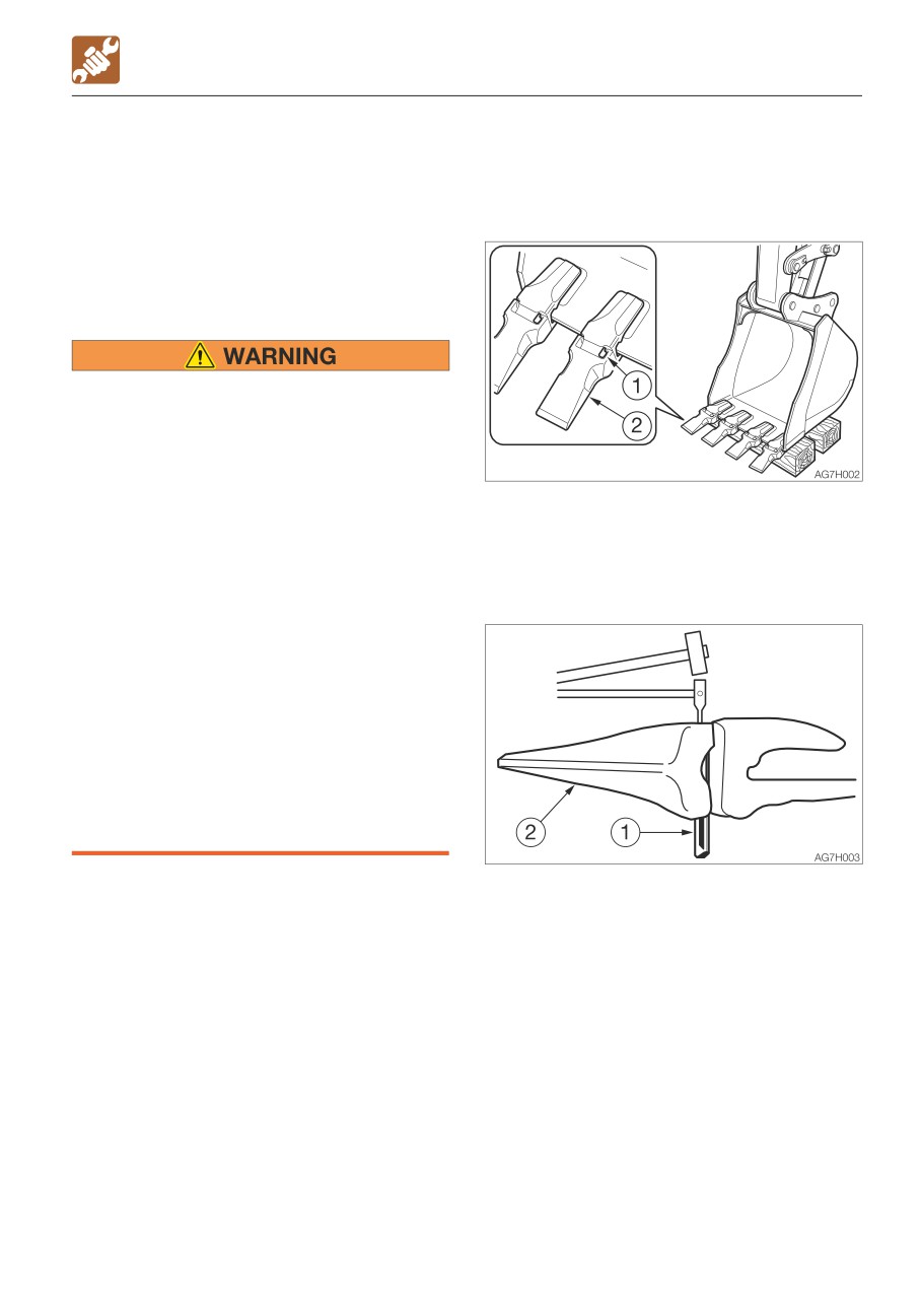
• Bucket tooth <V13SY or V17S>
WHEN REQUIRED
Removal
REPLACING THE BUCKET TEETH AND
1. Clean the bucket and park the machine in
THE SIDE CUTTERS
a flat, safe place where the ground is hard.
Replace the bucket teeth and the side
cutters when the tooth points or the side
cutters are worn. Do not wait until the
adapter or bucket is damaged.
• Before performing maintenance or
repairs under the machine, lower all
moveable working equipment to the
ground or in the lowermost position.
• To prevent unexpected movement,
firmly secure the working equipment
2. Set the bottom surface of the bucket flat
when repairing or replacing the bucket
and lower it on a block so that the locking
teeth or side cutter.
pin (1) can be knocked out.
• When using a hammer, pins may fly out
3. Remove the key, then check that the
or metal particles may be scattered.
bucket is stable.
This may lead to serious injury.
· If hard metal parts such as pins,
bucket teeth, side cutter or bearings
are hit with a hammer, wear protective
gear such as safety goggles and
gloves.
· When hitting pins or bucket teeth,
always check that there is no one in
the surrounding area.
• Do not allow unauthorized personnel in
the work area while working.
4. Place a rod against the locking pin (1) and
knock the locking pin out by hammering
against the rod.
The rod should be round and thinner than
the locking pin.
5-53
MAINTENANCE
WHEN REQUIRED
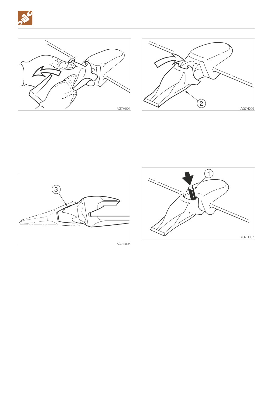
5. Remove the tooth point (2). Some tooth
2. Put the tooth point (2) in the adapter nose
points (2) are of the type that are removed
(3).
by turning (twisting) them
Push in firmly until the tooth point (2)
counterclockwise.
touches the tip of the adapter nose(3).
The same procedure can be used to
Some tooth points (2) are of the type that
remove the other tooth points.
are installed by turning (twisting) them
clockwise.
Installation
3. Insert the locking pin (1), making sure it is
1. Clean the adapter nose (3). If there is
in the right direction.
gravel or mud on the adapter nose, the
tooth point will not go in all the way and
the pin cannot be driven in.
5-54
MAINTENANCE
WHEN REQUIRED
• Side cutter
Installation
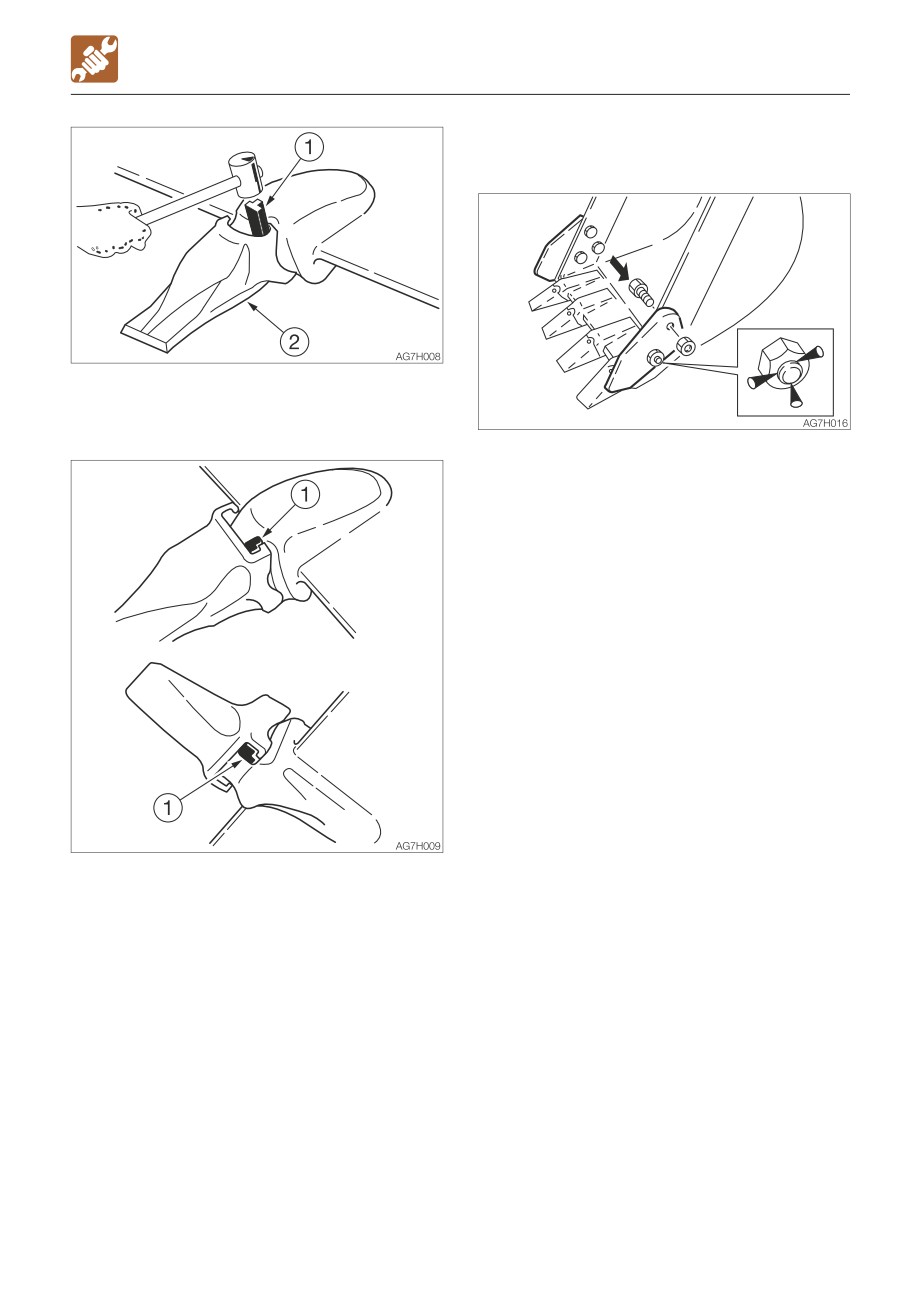
4. Drive in the locking pin (1) with a hammer
until it is flush with the tip of the tooth
point (2) ear.
1. Insert the bolts from the inner of the
bucket and tighten the side cutterwith
nuts.
Tightening torque: 241 N·m (178 ft-lb)
2. Caulk the bolts with a punch at three
spots along the periphery of the screw to
prevent the nuts from coming loose.
5. The locking pin (1) is now driven in.
The same procedure can be used to install
the other tooth points.
5-55
MAINTENANCE
WHEN REQUIRED
REPLACING THE BUCKET
Removing
• Before performing maintenance or
repairs under the machine, lower all
working equipment to the ground or in
the lowermost position.
• If maintenance must be performed with
the engine running, always work as a
two person team communicating each
other.
· One person must sit in the operator’s
seat so that he/she can immediately
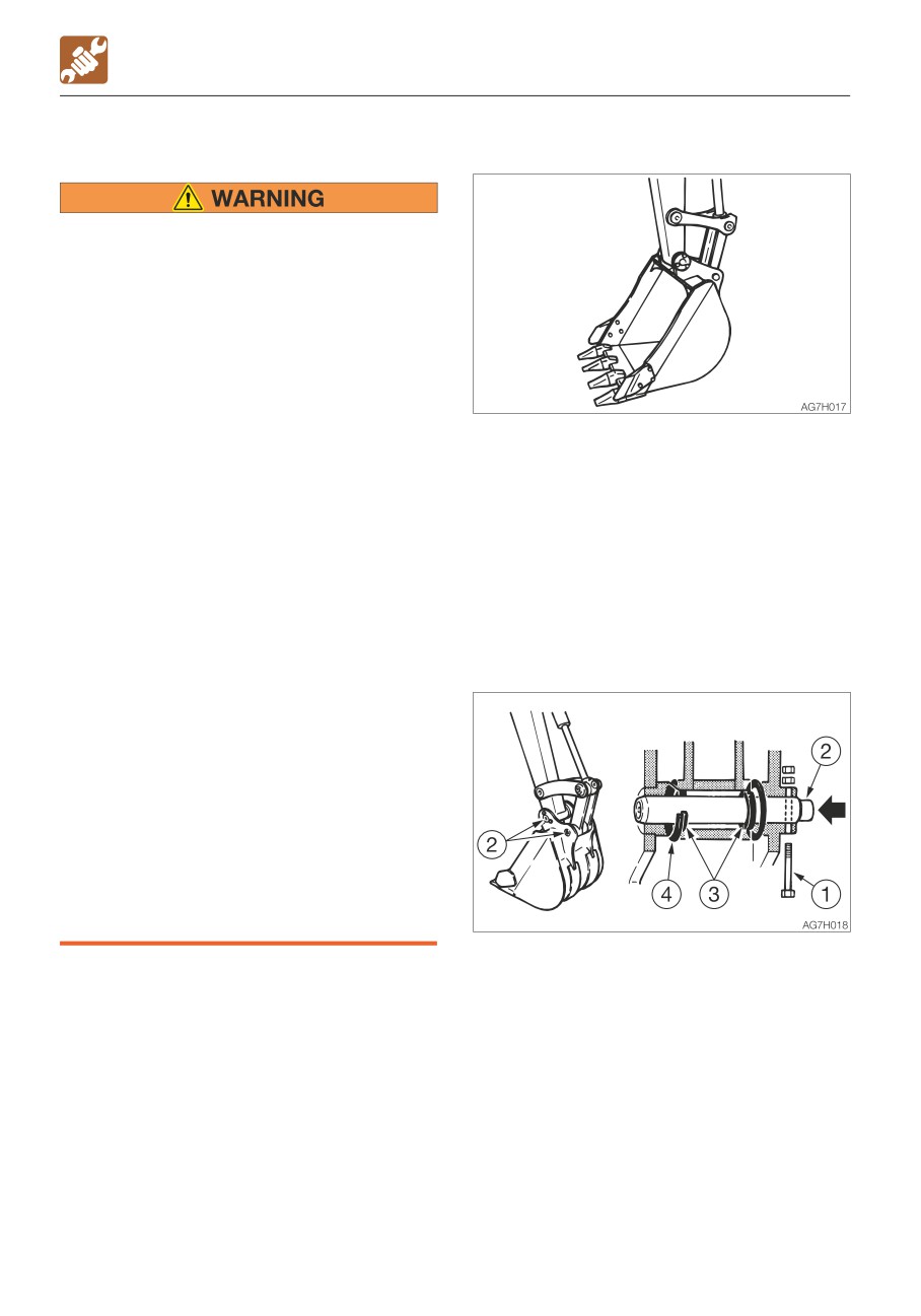
1. Lower the bucket to the ground as shown
stop the engine when necessary. He/
on the figure above in a stable position.
she must take care not to touch the
lever or pedal unless necessary.
Note: When removing pins, set the bucket
· The one who performs maintenance
so that it is barely touching the ground. If the
must make sure to keep his/her body
bucket is firmly touching the ground, the
or clothing away from the moving part
resistance will be great and it will be difficult
of the machine.
to remove the pin.
• When using a hammer, pins may fly out
or metal particles may be scattered.
2. Set the safety lock lever to the locked
This may lead to serious injury.
position and stop the engine.
· If hard metal parts such as pins,
bucket teeth, side cutter or bearings
are hit with a hammer, wear protective
gear such as safety goggles and
gloves.
· When hitting pins or bucket teeth,
always check that there is no one in
the surrounding area.
• When aligning the pin holes, always do
so by checking them visually. Do not
insert your finger in the pin hole, or you
could lose your finger.
3. Remove the bolt (1).
4. Hammer the pin (2) out of the bucket.
5. Remove the bucket.
Inspect the pin seal (3) and replace it if it is
deformed or damaged. (See next page.)
5-56
MAINTENANCE
WHEN REQUIRED
Installation
5. Adjust the gap between the bucket and
the arm.
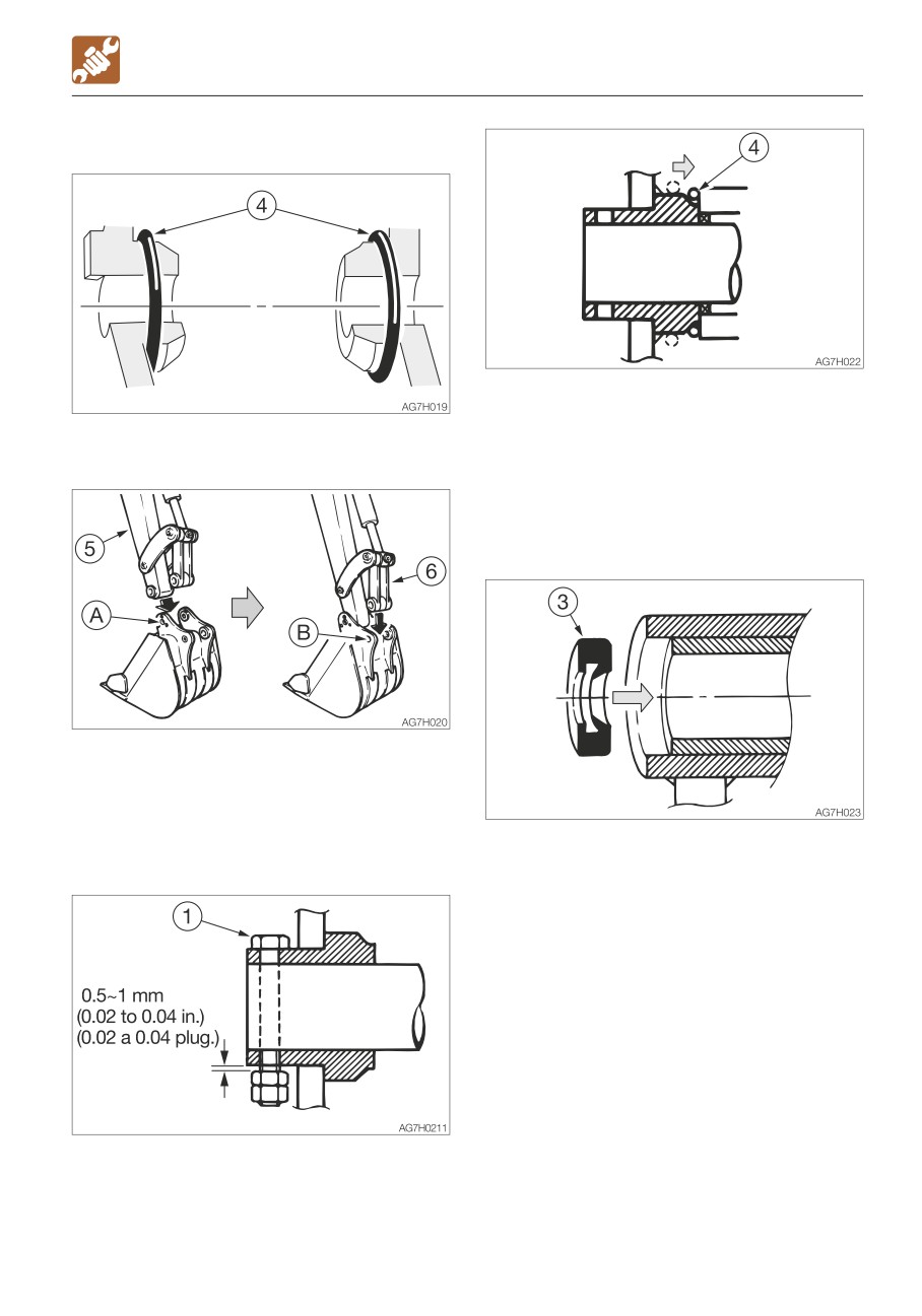
1. Set the O-ring (4) on the bucket as shown
Refer to “Adjusting the gap between the
on the figure above.
bucket and arm (If equipped)” on page
5-58.
6. Slide the O-ring (4).
Replacing the pin seal
2. Align the pin hole (A) on the bucket with
the pin hole on the arm (5), and install the
pin (2).
3. Operate the cylinder, align the pin hole (B)
on the bucket with the pin hole on the link
1. Set the pin seal (3) in the direction shown
arm (6), and install the pin (2).
on the figure above.
2. Use a mallet to slowly press the pin seal
in. Be careful not to damage the seal.
4. Align the turn prevention holes, and then
install the bolt (1) and the nut. Be sure to
leave a gap of about 0.5 to 1 mm (0.02 to
0.04 in.) between the nut and bucket
bush, or the nut will come loose.
5-57
MAINTENANCE
WHEN REQUIRED
ADJUSTING THE GAP BETWEEN THE
BUCKET AND ARM (IF EQUIPPED)
• Before performing maintenance or
repairs under the machine, lower all
working equipment to the ground or in
the lowermost position.
• To prevent unexpected movement,
securely block the working equipment
when adjusting the gap.
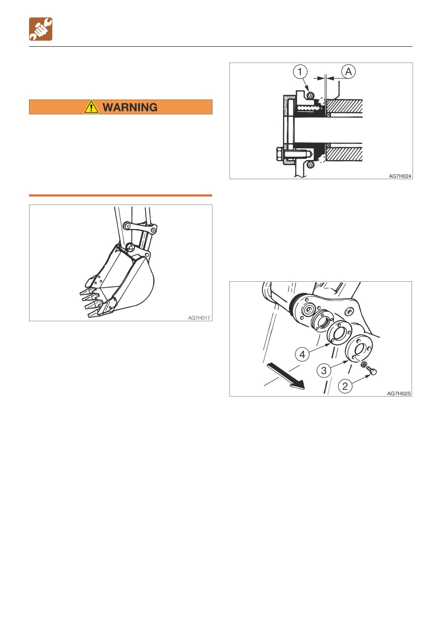
3. Move the O-ring (1) to bring the gap (A)
into view and measure the width of the
gap (A).
The gap (A) should be 0.5 mm (0.02 in.).
Swing the upperstructure slightly to the left
and lightly press the arm point to the left
side of the bucket (the side without an
adjuster).
1. Lower the bucket to the ground as shown
on the figure above in a stable position.
2. Check that the bucket dose not move,
and then set the safety lock lever to the
locked position and stop the engine.
4. Remove the three bolts (2), the end plate
(3) and flange (4).
5-58
MAINTENANCE
WHEN REQUIRED
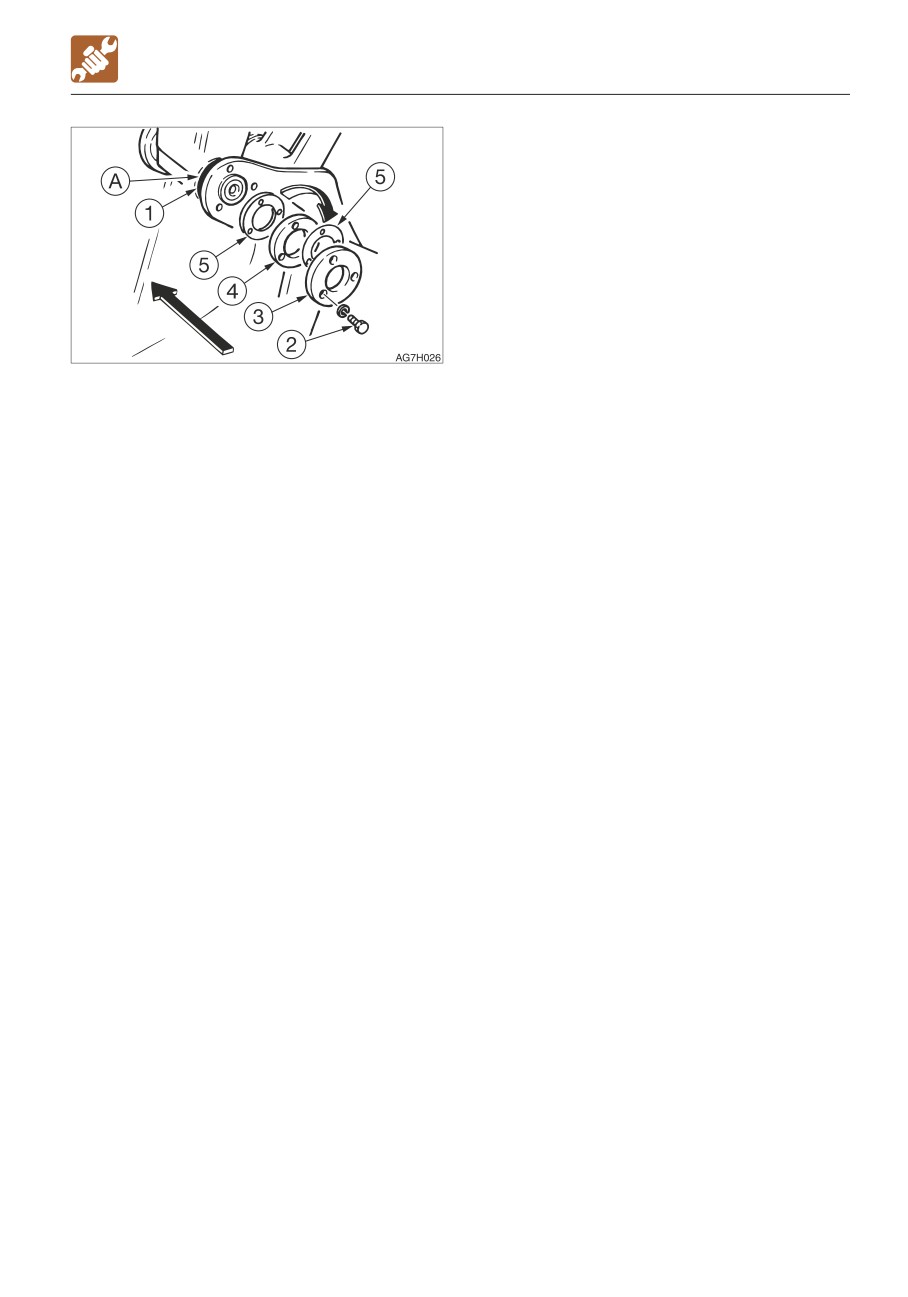
5. Pull out the adjustment shim(s) (5)
corresponding to the gap (A) from
between the flange (4) and the bucket
body.
Adjustment shim thickness : 0.5 mm (0.02
in.)
Be careful that the gap is no less than 0.5
mm (0.02 in.) after adjustment.
Note:
Example (for a gap of 2 mm or 0.08 in.):
2 mm - 0.5 mm (standard value)= 1.5 mm
(0.06 in.)
In the above example, three shims (5) should
be removed.
6. Insert the adjustment shim(s) (5) removed
in step 5 above between the end plate (3)
and the flange (4), and then fasten it in
place with the three bolts (2).
· Tightening torque for bolts (2): 83 N·m
(61.5 ft-lb.)
7. Return the O-ring (1) to the original
position.
5-59
MAINTENANCE
WHEN REQUIRED
LUBRICATING THE LEVERS AND PEDALS
Boom swing pedal
Set the machine to the parking posture,
stop the engine, remove the starter key
and store it. Failure to do so may result in
the machine moving abruptly, leading to
serious injury or death.
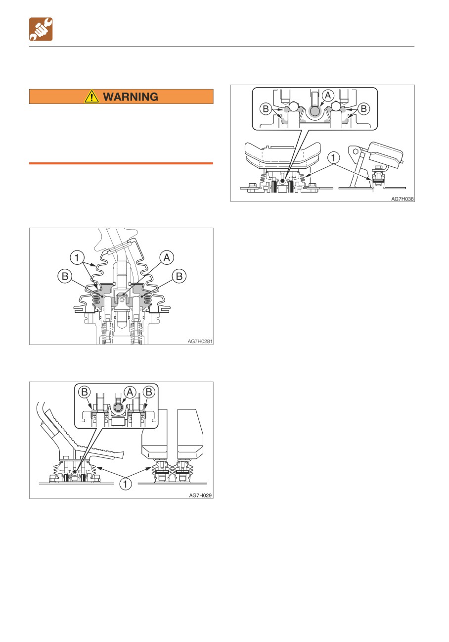
If the levers or pedals no longer move
smoothly, grease them.
Operating levers
1. Remove the lower mount section of the
boot (1) and turn it upward.
2. Wipe off the old grease.
3. Apply grease to points (A) and (B).
4. Set the boot (1) back as it was.
Travel levers/pedals
5-60
MAINTENANCE
WHEN REQUIRED
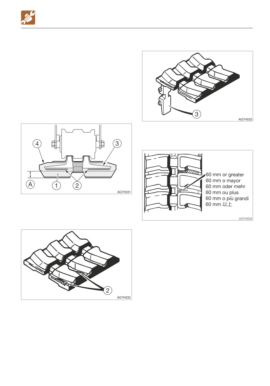
INSPECTING THE RUBBER CRAWLERS
(3) Metal core
Repair or replace the rubber crawlers if their
condition becomes as described below.
Consult your sales or service dealer for repair
or replacement.
Rubber crawler
Replace the crawler if the entire crawler is
stretched and cannot be adjusted.
(1) Lug
Replace if even one metal core is off.
(4) Rubber
Replace if the height of (A) is 5 mm (0.2 in.)
or below.
(2) Steel cord
Repair if there are cracks of 60 mm (2.4 in.)
or greater in length.
If the steel cord is visible, repair as soon as
possible, regardless of the length of the
crack.
Replace if the steel cord is exposed for two
links or more.
Replace if the half or more of the steel cords
on one side are cut.
5-61
MAINTENANCE
WHEN REQUIRED
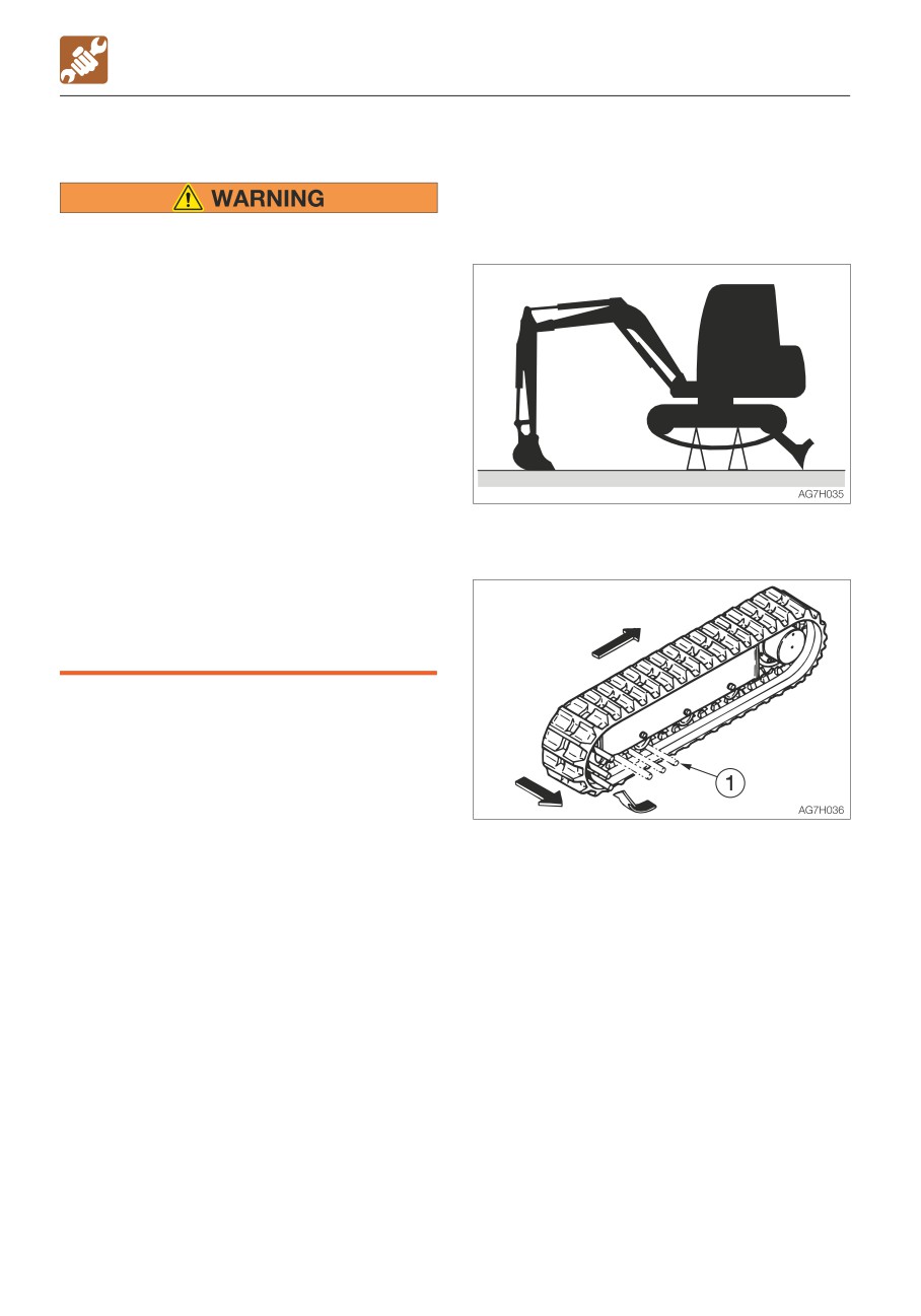
REPLACING THE RUBBER CRAWLERS
Removal
1. Fully release the tension of the rubber
crawler.
Refer to “Inspecting and adjusting the
• If you must work beneath the raised
crawler tension” on page 5-26.
machine or working equipment, always
use wood blocks, jack-stands or other
rigid and stable supports. Never get
under the machine or working
equipment if they are not sufficiently
supported.
• If maintenance must be performed with
the engine running, always work as a
two person team communicating each
other.
· One person must sit in the operator’s
seat so that he/she can immediately
stop the engine when necessary. He/
2. Use the working equipment to lift the
she must take care not to touch the
body.
lever or pedal unless necessary.
· The one who performs maintenance
must make sure to keep his/her body
or clothing away from the moving part
of the machine.
3. Set an iron pipe (1) in the rubber crawler
and turn the sprocket slowly in the reverse
direction.
4. Turn until the iron pipe (1) is directly next to
the idler and the rubber crawler lifts away
from the idler, then stop turning the
sprocket.
5. Slide the rubber crawler sideways and
remove it from the crawler frame.
Remove the other rubber crawler using
the same procedure.
5-62
MAINTENANCE
WHEN REQUIRED
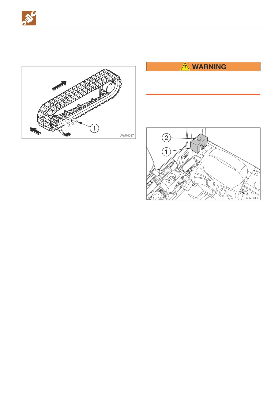
Installation
INSPECTING AND REPLENISHING THE
1. Use the working equipment to lift the
WINDSHIELD WASHER FLUID
body.
Choose ethyl alcohol as washer solution.
Do not use methyl alcohol as washer
solution. It could damage the eyes.
Use a windshield washer fluid designed
specifically for motor vehicles. Follow the
instructions included with the washer fluid.
2. Set the rubber crawler on the sprocket.
3. Set an iron pipe (1) in the rubber crawler
and turn the sprocket slowly in the reverse
direction.
4. Turn until the iron pipe (1) is directly next to
the idler and the rubber crawler lifts away
from the idler, then stop turning the
sprocket.
5. Slide the rubber crawler inward, engage it
on the idler, then pull out the iron pipe.
6. Check that the rubber crawler is securely
Inspection
engaged on the sprocket and idler.
1. Open the cab door.
7. Tighten the rubber crawler to the standard
2. Inspect the washer tank (1) and add
tension.
washer fluid if the level is low.
Refer to “Inspecting and adjusting the
crawler tension” on page 5-26.
Replenishing
8. Install the other rubber crawler using the
1. Mix the washer fluid to the prescribed
same procedure.
concentration.
2. Remove the cap (2) and add washer fluid.
Keep the dust away while replenishing the
washer fluid.
3. Install the cap (2).
5-63
MAINTENANCE
MAINTENANCE DURING EXTENDED STORAGE PERIOD
Starting the machine after storage
MAINTENANCE DURING
IMPORTANT: If the above “Storage
EXTENDED STORAGE PERIOD
procedures” have not been followed
Storage procedures
during the extended storage periods,
If the machine is to be stored for 30 days or
consult your sales or service dealer
more, store it indoors. If it must be stored
before starting the machine again.
outdoors, park the machine on a surface laid
with lumber on a flat ground, and place a
1. Wipe off the rust-inhibiting oil that was
waterproof cover over it so that it stays dry.
applied on the piston rods of the hydraulic
1. Clean the machine.
oil cylinders.
2. Inspect for oil leakage, water leakage,
2. Add oil or grease as necessary.
cracks and loose nuts and bolts.
3. Add fuel and replace the hydraulic oil and
Returning the engine to service
oil.
1. Perform the daily checks.
4. To prevent rusting and freezing, replace
2. The engine should be pre-oiled before
the engine coolant with long-life coolant
startup.
(LLC).
a. Crank the engine, leaving the fuel
Refer to “Cleaning the engine cooling
system shut off so the engine will not
system” on page 5-48.
start, for 15 seconds.
5. Use the grease gun to lubricate the grease
b. Then pause for 30 seconds.
fittings.
c. Repeat the procedure until you have
6. Fully retract the bucket and arm cylinders
cranked the engine for a total of one
and lower the bucket and dozer blade to
minute. This will circulate the oil in the
the ground.
engine’s lubrication system.
7. Apply rust-inhibiting oil to the hydraulic
3. Prime the fuel system.
cylinder rods.
4. Start the engine. Allow the engine to idle
8. Disconnect the negative cable from the
for approximately 15 minutes while you
battery and cover the battery to prevent
check for:
freezing.
· Proper oil pressure
· Fuel, engine oil or coolant leaks
During storage
· Proper operation of the indicators and/or
gauges
5. Avoid prolonged operation at minimum or
• Do not operate the machine in an
maximum engine speeds and loads for the
enclosed area without adequate
remainder of the first hour of operation.
ventilation.
• If natural ventilation is not possible,
install ventilators, fans, exhaust
extension pipes or other venting
devices.
1. To prevent rusting, operate the machine
once a month so that the oil can be
circulated throughout the system.
2. Inspect the battery and recharge it as
necessary.
Ask your sales or service dealer for
recharging.
5-64
TROUBLESHOOTING
6-1
TROUBLESHOOTING
SYMPTOMS THAT ARE NOT MALFUNCTIONS
• It becomes less easy to operate the
SYMPTOMS THAT ARE NOT
machine when an attachment weighing
more than a standard arm or bucket is
MALFUNCTIONS
installed.
The symptoms listed below are not
malfunctions.
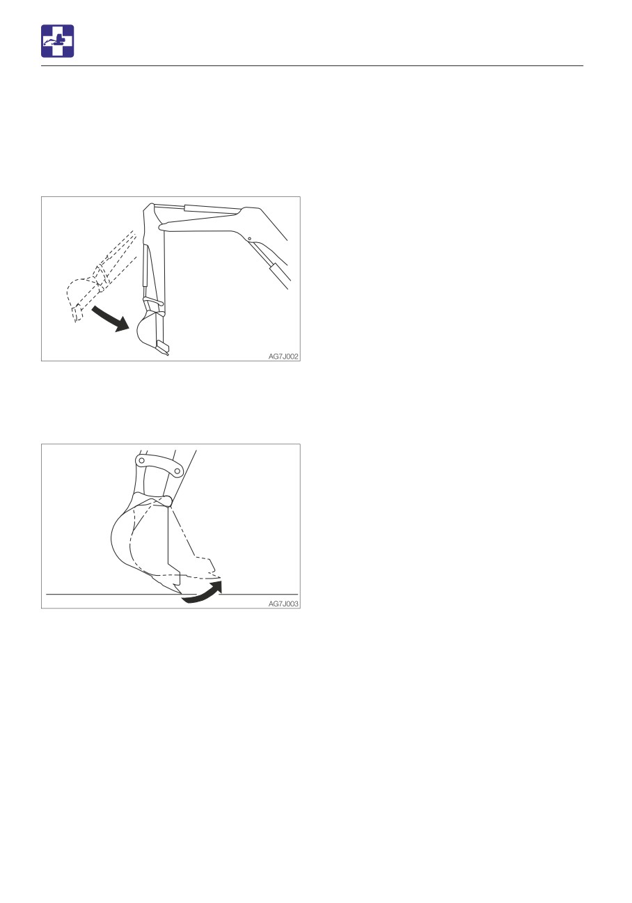
• The arm retracting speed momentarily
slows down when it reaches an almost
vertical position while the engine is running
at low speed.
• The bucket teeth moving speed
momentarily slows down when it reaches
an almost horizontal position while the
engine is running at low speed.
• The slew motor produces noise at the
beginning and end of the slewing.
• The travel motor produces noise when
stopped suddenly from its high speed
traveling.
• The control valve produces noise if
excessive force is applied to the working
equipment or when it moved to the stroke
end.
6-2
TROUBLESHOOTING
IF THE ENGINE OVERHEATS
Remedy procedure
IF THE ENGINE OVERHEATS
1. Park the machine in a safe place.
2. Check if steam is coming out of the closed
engine hood and covers.
• Do not open the engine hood and
3. If there is steam, stop the engine
covers when steam is coming from it.
immediately and contact your sales or
The steam or hot water may spurt out
service dealer for repair. If steam, is not
and cause burns.
coming out run the engine at low idle and
• Do not try to remove the radiator cap or
let the water temperature cool down.
the drain plug when the cooling water is
4. When the water temperature gauge LED
hot. Stop the engine, wait until the
drops in the green zone, stop the engine.
engine and the radiator cool, and then
5. Perform the inspections and the remedies
slowly loosen the radiator cap to release
listed below once the engine cools down.
the internal pressure.
· Fan belt slack
Adjust
• Before performing maintenance, stop
Refer to page 5-24.
the engine and allow the machine to
· Coolant level
Add
cool down.
Refer to page 5-18.
· Water leakage
Repair
The symptoms listed below indicate
· Radiator fins
Clean
overheating.
Refer to page 5-40.
· Sediment in cooling system
............................... Clean
Refer to page 5-48.
If the problem persists after the above
remedies, contact your sales or service
dealer for repair.
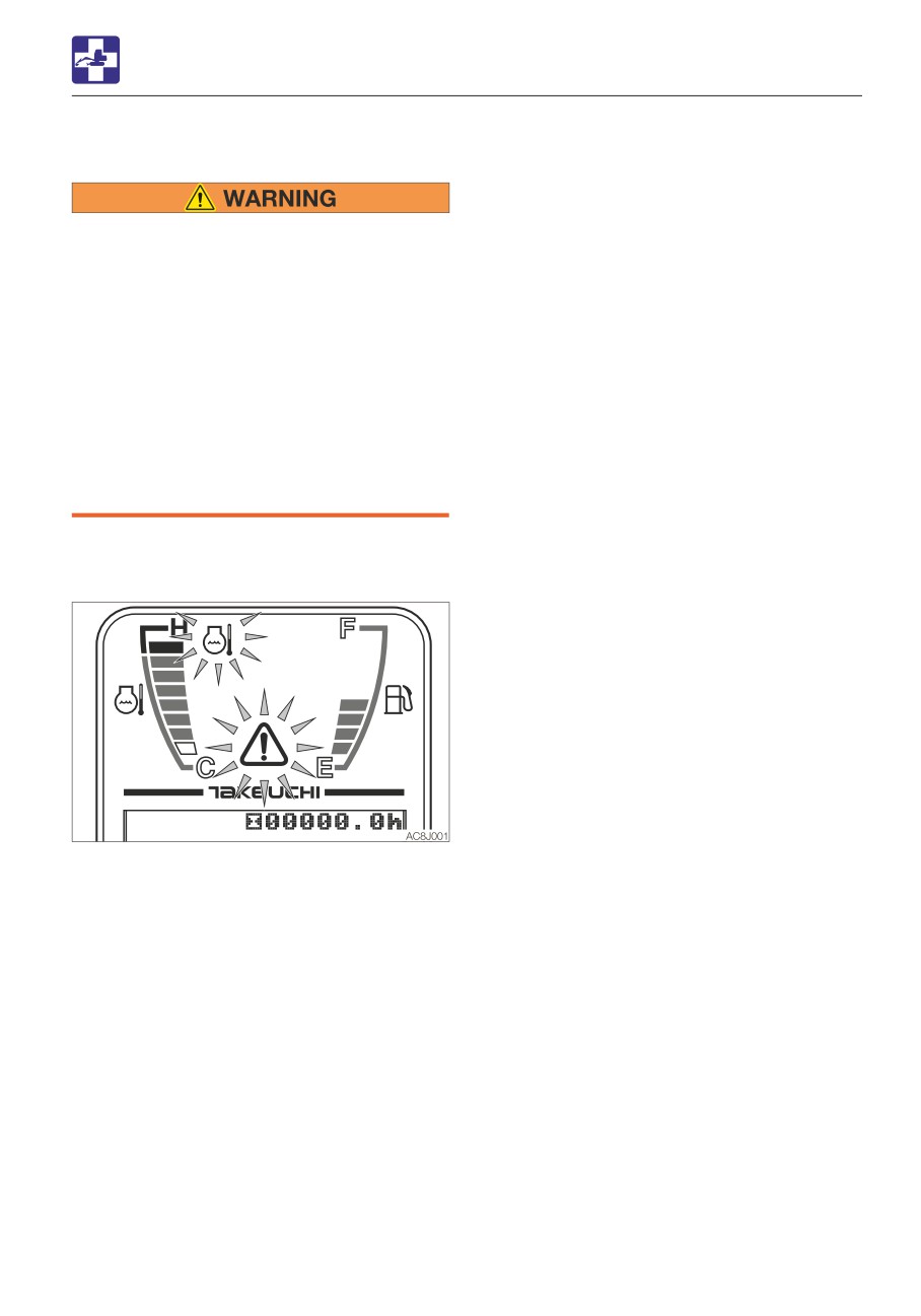
• An alarm is sounded and the engine
emergency lamp and the coolant
temperature warning lamp start flashing.
• The water temperature gauge LED is in the
red zone.
• Steam comes from the engine room.
6-3
TROUBLESHOOTING
IF THE BATTERY GOES DEAD
Connecting the jumper cables
IF THE BATTERY GOES DEAD
The symptoms below indicate that the
IMPORTANT: Set the starter keys of the
battery is dead.
booster vehicle and the dead machine to
• The starter motor does not turn or fails to
the OFF position.
start the engine.
• The horn is too weak.
Remedy procedure
Start the engine using the booster battery on
the other vehicle (booster vehicle) and the
jumper cables.
• When starting the engine using the
jumper cables, be sure to connect the
cables by following the proper steps.
Improper use of jumper cables can
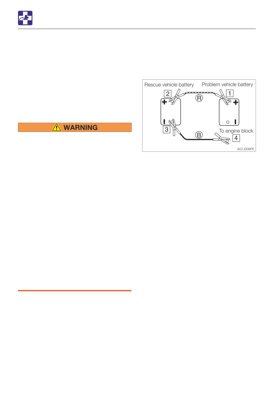
1. Connect the clip of jumper cable (R) to the
result in battery explosion or
positive (+) battery terminal of the dead
unexpected machine motion.
machine.
· Do not allow the booster vehicle and
2. Connect the other clip of jumper cable (R)
the machine with a dead battery (dead
to the positive (+) battery terminal of the
machine) to touch each other.
booster vehicle.
· Do not allow the positive (+) and the
3. Connect the clip of jumper cable (B) to the
negative (-) clips of the jumper cables
negative (-) battery terminal of the booster
to touch each other.
vehicle.
· When connecting, attach the jumper
4. Connect the other clip of jumper cable (B)
cable to the positive (+) terminals first.
to the engine block of the dead machine.
When disconnecting, remove the
Connect the clip to a place as far from the
cable from the negative (-) terminal
battery as possible.
(ground) first.
· Connect the last clip of the jumper
Starting the engine
cable to a point as far away from the
1. Check that the clips are securely
battery as possible.
connected to the terminals.
• Always wear the protective goggle when
2. Start the engine of the booster vehicle and
jump starting the engine by using the
run it at high speed.
jumper cables.
3. Start the engine of the dead machine.
IMPORTANT: Use the jumper cables and
clips of a size suited to the capacity of
battery. Do not use damaged or corroded
jumper cables and clips.
IMPORTANT: Be sure that the battery of
the booster vehicle has the same
capacity as the battery of the dead
machine.
IMPORTANT: Be sure to connect the clips
securely.
6-4
TROUBLESHOOTING
IF THE BATTERY GOES DEAD
Disconnecting the jumper cables
Once the dead machine is successfully
running, remove the jumper cables by
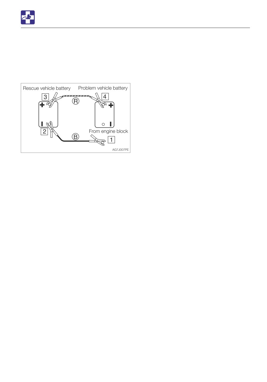
following the same steps as for connection in
the reverse order.
1. Disconnect the clip of jumper cable (B)
from the engine block of the dead
machine.
2. Disconnect the other clip of jumper cable
(B) from the negative (-) battery terminal of
the booster vehicle.
3. Disconnect the clip of jumper cable (R)
from the positive (+) battery terminal of the
booster vehicle.
4. Disconnect the clip of jumper cable (R)
from the positive (+) battery terminal of the
dead machine.
Recharging
Ask your sales or service dealer for
recharging the dead battery.
6-5
TROUBLESHOOTING
IF A FUSE BLOWS
Fuse layout and circuits protected
IF A FUSE BLOWS
If a light does not come on or the electrical
system does not work, a fuse may be blown.
Inspect the fuses.
INSPECTING AND REPLACING THE FUSE
If the fuse blows again soon after
replacement, then the electric system is
likely faulty. It may pose a fire hazard if
not properly repaired. Contact your sales
or service dealer for advice.
1. Turn the starter key to the OFF position to
stop the engine.
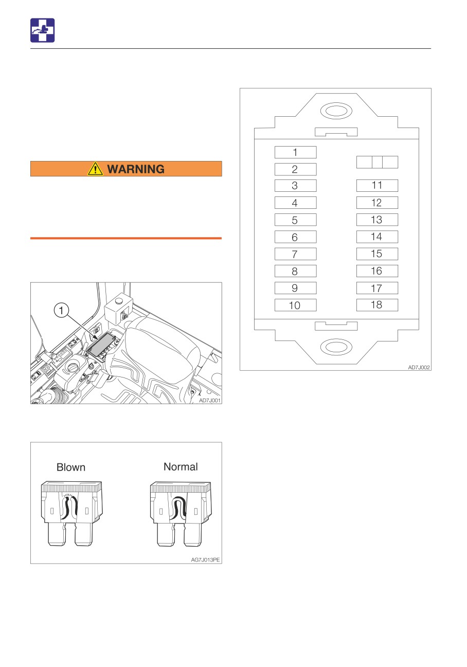
2. Open the fuse box cover (1).
3. Check for any blown fuses.
4. If a fuse is blown, replace it with a spare
fuse of the same capacity.
6-6
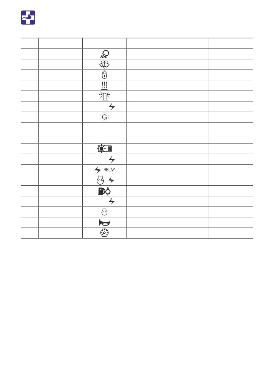
TROUBLESHOOTING
IF A FUSE BLOWS
No.
Capacity
Symbol
Protected circuit
Fuse No.
1
15A
Lights
F1
2*
15A
Wiper
F2
3
10A
Safety lock lever
F3
4*
10A
Heater
F4
5
15A
Beacon
F5
6
15A
CAB
00
Cab
F6
7
10A
Alternator relay
F7
8
15A
OPT
Option
F8
9
−
F9
10
5A
Switch lighting
F10
11
20A
CTL 00
Controller power supply
F11
12
10A
ACC relay
F12
13
30A
Engine
F13
14
5A
Feed pump
F14
15
5A
CTL 00
Controller power supply
F15
16
20A
Starter switch
F16
17
10A
Horn
F17
18
10A
Cluster
F18
*: Only for cab
6-7
TROUBLESHOOTING
IF A FUSE BLOWS
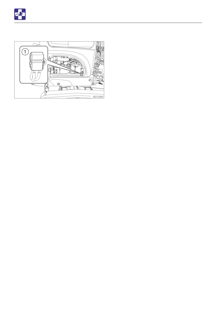
INSPECTING THE FUSIBLE LINK
If the machine is not turned on after turning
the starter switch to the ON position, the
cartridge type fusible link (1) is likely blown.
Open the maintenance cover and inspect. If
the fusible link is blown, please contact your
sales or service dealer.
Note: Fusible links are large type fuses used
in high current applications. Like a regular
fuse, they act as fuses by protecting the
electric components and wirings from
damage caused by excessive current draw.
6-8
TROUBLESHOOTING
RESTARTING AFTER ADDING FUEL
Note: Air in the fuel system causes the
RESTARTING AFTER ADDING
engine to fail to start or to have other
problems. Always bleed air when the fuel
FUEL
tank is emptied or when there is air in the
BLEEDING AIR FROM THE FUEL SYSTEM
fuel system.
IMPORTANT: NEVER use the starter
motor to crank the engine in order to
prime the fuel system. This may cause the
starter motor to overheat and damage the
coils, pinion gear and/or ring gear.
IMPORTANT: If the engine stalls due to
fuel shortage, add fuel, turn the key to the
ON position for 60 seconds, and then turn
it to the START position. Running the
starter for a long time before there is
enough fuel is going through can cause
the starter to fail.
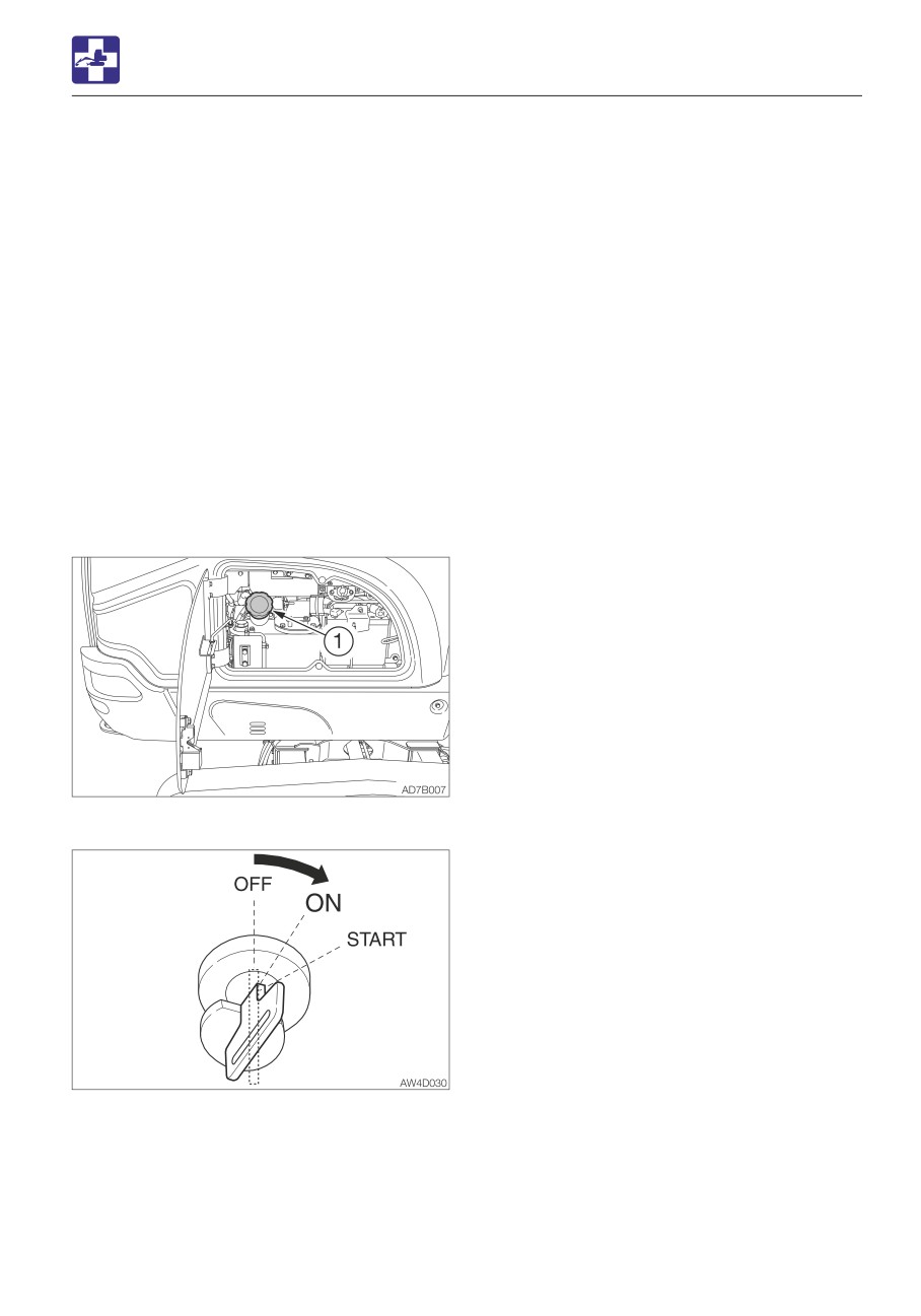
1. Add fuel.
2. Turn the starter key to the ON position and
hold it for about 60 seconds.
The automatic air bleeder bleeds air from
the fuel system.
6-9
TROUBLESHOOTING
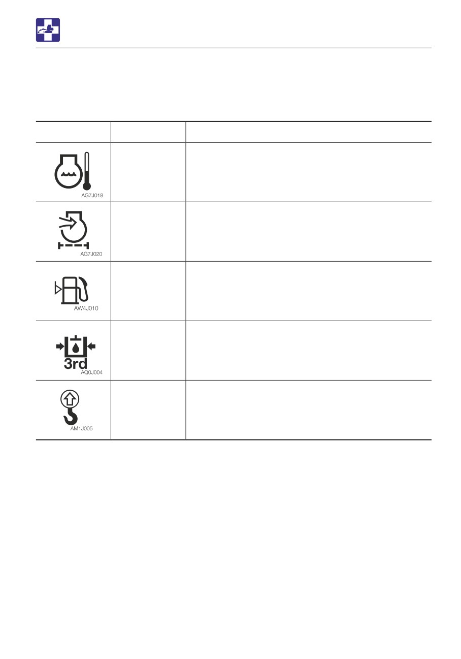
IF A WARNING LAMP FLASHES
IF A WARNING LAMP FLASHES
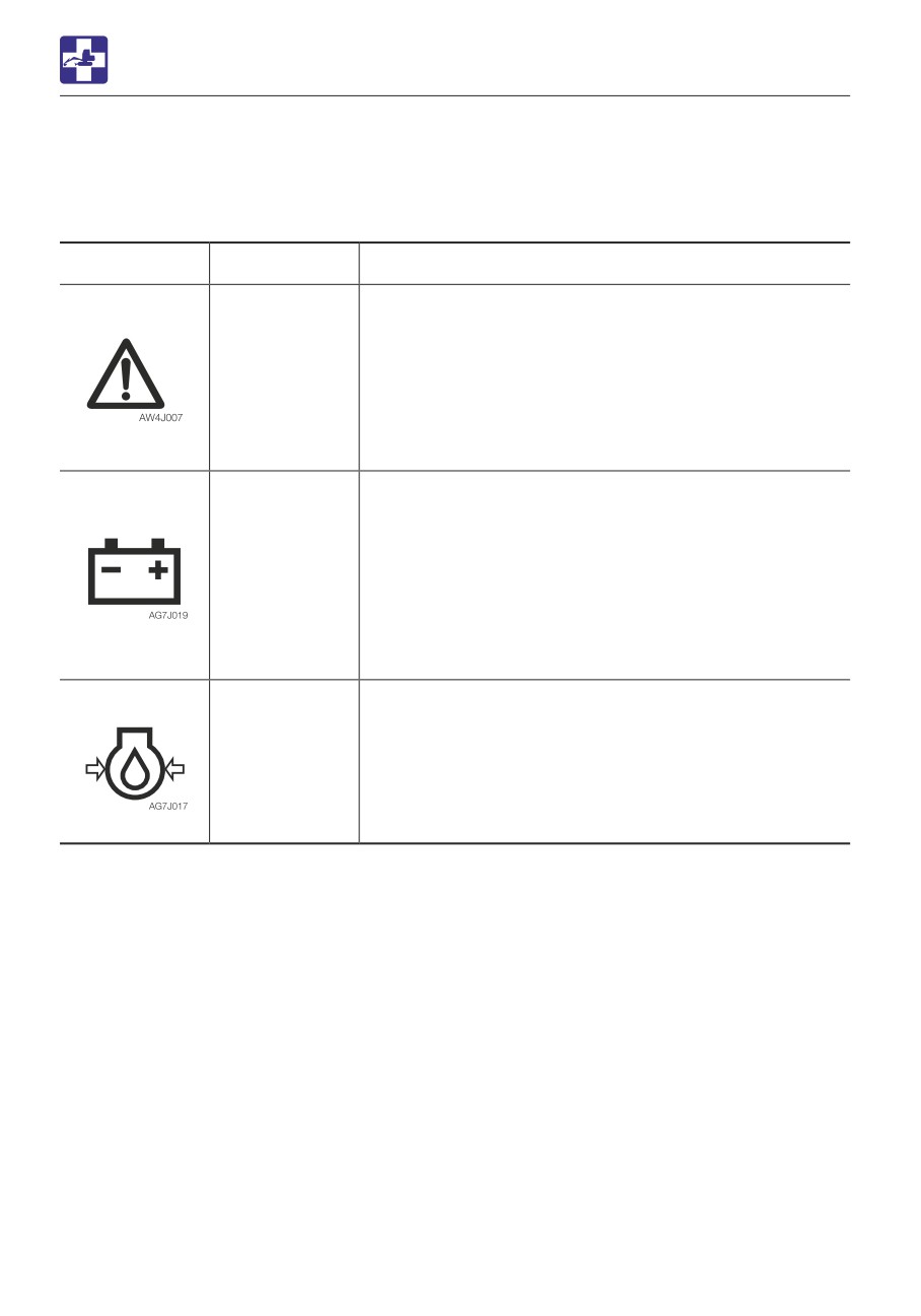
If an alarm is sounded or a warning lamp starts flashing during operation, park the machine in
a safe place and perform the remedy procedures described below.
Warning lamp
Lamp name
Causes and remedies
Vehicle and
There is a problem in the machine.
engine
Refer to the respective warning lamp below.
emergency
Get the vehicle error code number from the instrument
lamp
cluster, and then consult your sales or service dealer
referring to the “Vehicle error code list”.
Refer to “Instrument cluster” on page 2-16.
Refer to “Vehicle error code list” on pages 6-12 and
6-13.
Battery charge
There is a problem with the fan belt or charger.
warning lamp
Check the fan belt for slack or breakage and adjust as
necessary.
If the lamp continues flashing after maintenance, there is
likely a problem with the charger. Consult your sales or
service dealer for help.
Refer to “Inspecting and adjusting the fan belt” on page
5-24.
Engine oil
There is a problem in the engine lubrication system.
pressure
warning lamp
Check the engine oil level. If the lamp is flashing when
the level is normal or even after replenishment of oil or
coolant, consult your sales or service dealer.
Refer to “Inspecting and replenishing the engine oil” on
page 5-19.
6-10
TROUBLESHOOTING
IF A WARNING LAMP FLASHES
Warning lamp
Lamp name
Causes and remedies
Coolant
The coolant temperature is too high and the engine is
temperature
overheating.
warning lamp
Refer to “If the engine overheats” on page 6-3.
Air cleaner
The air cleaner is clogged. Clean it.
warning lamp
Refer to “Cleaning the air cleaner” on page 5-38.
Fuel level
The fuel level is too low. Add fuel.
warning lamp
Refer to “Inspecting the fuel level” on page 5-20.
Third auxiliary
Pressure in the third auxiliary hydraulic line is too low
hydraulic
warning lamp
Consult your sales or service dealer for help.
Lift overload
This lamp starts flashing if the overload warning device is
warning
activated. If it occurs, reduce the load to be lifted.
indicator lamp
Refer to “Lift overload warning switch (If equipped)” on
page 2-45.
6-11
TROUBLESHOOTING
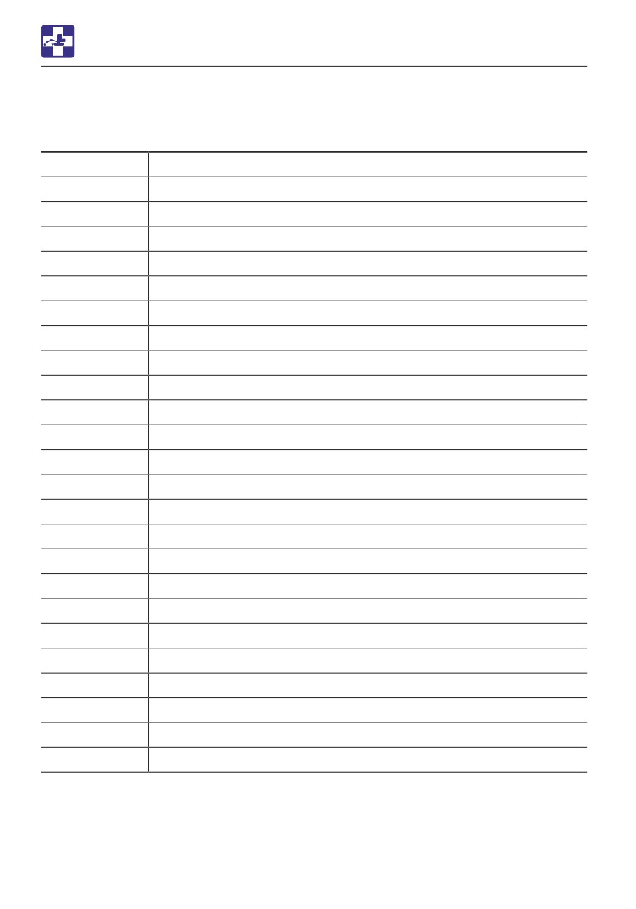
VEHICLE ERROR CODE LIST
VEHICLE ERROR CODE LIST
If an error code appears on the display, consult your sales or service dealer.
Error code
Error details
9
Impossible to sense ACC key
402
CAN 0 communication error
602
CAN communication error (cluster gauge)
612
CAN communication error (OX024)
1703
Main power supply voltage error (too high)
1704
Main power supply voltage error (too low)
1713
OX024 power supply voltage error (too high)
1714
OX024 power supply voltage error (too low)
2503
Sensor voltage error (too high) MMC
2504
Sensor voltage error (too low) MMC
3300
Alternator charge faulty
3401
Engine oil pressure error
3500
Overheat
3600
Air cleaner clogged
5303
Accelerator sensor error (too high)
5304
Accelerator sensor error (too low)
5353
Governor position sensor error (high pressure)
5354
Governor position sensor error (low pressure)
5505
Fuel gauge resistance value error (cable break)
5603
Lift alarm sensor error (too high)
5604
Lift alarm sensor error (too low)
6503
AUX1 slide switch voltage value error (too high)
6504
AUX1 slide switch voltage value error (too low)
6509
AUX1 slide switch neutral error
6-12
TROUBLESHOOTING
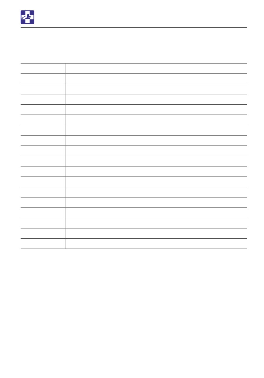
VEHICLE ERROR CODE LIST
Error code
Error details
6519
AUX1 (L) switch error
6529
AUX1 (R) switch error
6603
AUX2 slide switch voltage value error (too high)
6604
AUX2 slide switch voltage value error (too low)
6609
AUX2 slide switch neutral error
6709
AUX3 button error (Foot)
6719
AUX3 switch error (Grip)
8015
AUX1 (L) PWM output voltage error (too low)
8016
AUX1 (L) PWM output voltage error (too high)
8025
AUX1 (R) PWM output voltage error (too low)
8026
AUX1 (R) PWM output voltage error (too high)
8035
AUX2 (L) PWM output voltage error (too low)
8036
AUX2 (L) PWM output voltage error (too high)
8045
AUX2 (R) PWM output voltage error (too low)
8046
AUX2 (R) PWM output voltage error (too high)
8054
Throttle motor A (too low)
8064
Throttle motor B (too low)
PWM = Pulse width modulation
6-13

TROUBLESHOOTING
OTHER SYMPTOMS
OTHER SYMPTOMS
For symptoms not included in the table below or if the problem persists after the proper
remedies have been taken, consult your sales or service dealer.
Symptoms
Major causes
Remedies
Left and right operating levers
• Insufficient grease on the
• Grease the levers.
do not move smoothly
left and right operating
Refer to page 5-60.
levers
Blade lever and throttle lever
• Wire is stretched too lose
• Adjust or replace (ask your
do not move smoothly
sales or service dealer).
Hoe attachment, slewing or
• Safety lock lever is raised
• Lower (release) the safety
traveling operation not
(locked)
lock lever.
possible
Refer to page 2-46.
• Fuse is blown
• Replace the fuse.
Refer to page 6-6.
Digging force is insufficient
• Hydraulic oil level too low
• Add to the specified level.
Refer to page 5-21.
• Hydraulic oil is not warm
• Perform the warm-up.
enough
Refer to page 3-8.
• Air cleaner is clogged
• Clean the air cleaner.
Refer to page 5-38.
• Hydraulic oil is not of
• Replace the hydraulic oil.
suitable type
Refer to page 5-50.
Traveling is not possible or
• Stones or foreign objects
• Remove the foreign object.
not smooth
are stuck
Machine veers to the right/left
• Stones or foreign objects
• Remove the foreign object.
are stuck
• Faulty crawler tension
• Adjust the crawler to the
adjustment
prescribed tension.
Refer to page 5-26.
Travel speed cannot be
• Fuse is blown
• Replace the fuse.
changed
Refer to page 6-6.
6-14
TROUBLESHOOTING
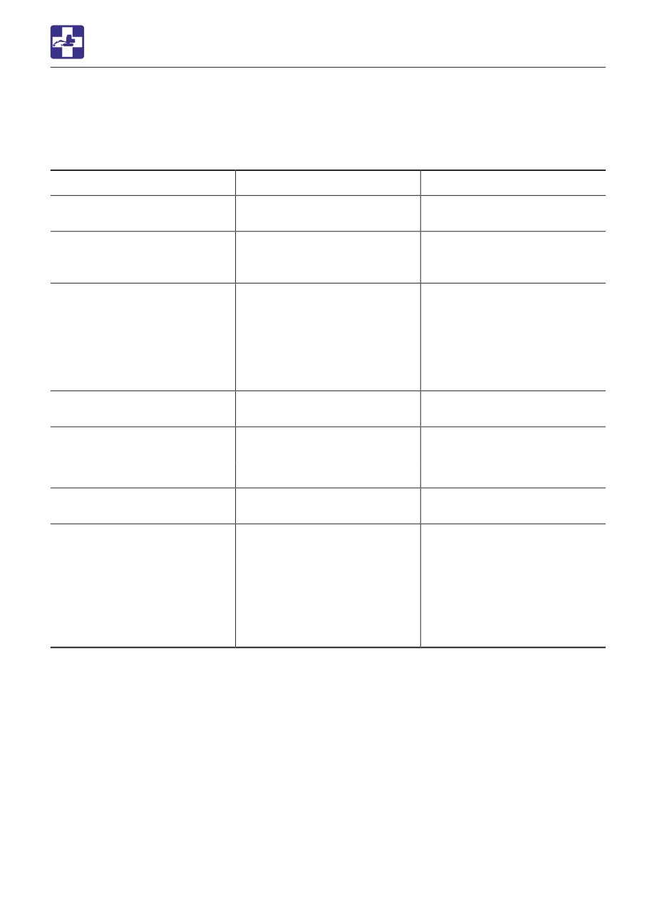
OTHER SYMPTOMS
Symptoms
Major causes
Remedies
Slewing is not possible or not
• Insufficient grease on slew
• Grease the bearing.
smooth
bearing
Refer to page 5-28.
Hydraulic oil temperature is
• Hydraulic oil level too low
• Add up to the specified
too high
level.
Refer to page 5-21.
Starter motor turns but
• Insufficient fuel
• Add fuel.
engine does not start
Refer to page 5-20.
• Air in fuel system
• Bleed air.
Refer to page 6-9.
• Water in fuel system
• Drain water.
Refer to page 5-29.
Crawlers come off
• Crawlers too loose
• Increase the tension.
Refer to page 5-26.
Engine exhaust is white or
• Excessive engine oil
• Adjust to the specified level.
bluish
Refer to page 5-19.
• Poor fuel
• Replace the fuel.
Engine exhaust is
• Air cleaner is clogged
• Clean the air cleaner.
occasionally black
Refer to page 5-38.
Irregular noise is produced
• Low quality fuel is being
• Replace the fuel.
from the engine
used
(combustion or mechanical
• Engine is overheating
• Refer to “If the engine
noise)
overheats” on page 6-3.
• Damage inside the muffler
• Replace the muffler.
For replacement, ask your
sales or service dealer.
6-15
TROUBLESHOOTING
LOWERING THE BOOM TO THE GROUND
PROCEDURE 2 (MACHINES WITHOUT
LOWERING THE BOOM TO
AN ACCUMULATOR)
This operation is dangerous and requires
THE GROUND
experience. Ask your sales or service dealer
If the hoe attachment must be lowered to the
for it.
ground while the engine is stopped, use the
following procedure.
• Stop the engine and allow the machine
PROCEDURE 1 (MACHINES WITH AN
to cool down before performing
ACCUMULATOR)
maintenance.
Perform this operation within 10 minutes
· The engine and the hydraulic system
after the engine stopping.
and many other parts of the machine
1. Sit at the operator’s seat.
are hot immediately after the engine is
2. Turn the starter switch to the ON position.
stopped. Touching these parts will
3. Lower the safety lock lever to the unlock
cause burns.
position
· The hydraulic oil is also hot and under
4. Slowly push the operating lever forward to
high pressure immediately after the
lower the boom.
engine is stopped.
Be careful when loosening the caps or
plugs. Working on the machine under
these conditions could result in burns
or injuries due to the hot oil spurting
out.
• Keep away from the working area when
the hoe attachment is lowered. You may
be hit by dirt falling out of the bucket or
the hoe attachment as it drops.
• Slowly turn the hose nut and lower the
boom at a slow pace.
• Do not loosen or remove the hoses not
located in the specified places. Oil may
spurt out if wrongly handled.
6-16

TROUBLESHOOTING
LOWERING THE BOOM TO THE GROUND
Equipped with emergency shut-off valve
Without emergency shut-off valve
1. Place a pan under the hose to catch the
1. Take out the bolt and remove the cover
waste oil.
(1).
2. Hold the hose fitting (1) with a wrench and
slowly loosen the hose nut (2) with another
wrench.
3. The oil in the boom cylinder is drained and
the hoe attachment is lowered.
4. After the hoe attachment is lowered to the
ground, check the safety and stability of
the machine.
5. Hold the hose fitting (1) with a wrench and
tighten the hose nut (2) with another
wrench.
· Tightening torque: 31.4 N·m (23.1 ft-lb.)
2. Remove the fitting (2).
3. Loosen the lock nut (3) while holding the
adjust screw (4) in place with a hexagonal
wrench so that the adjust screw (4) will not
be loosened together with the lock nut (3).
4. Turn the adjust screw (4) slowly 1/4 turn to
lower the boom.
5. Check for safety and stability of the
machine.
6. Return the adjust screw (4) to the original
position.
7. Tighten the lock nut (3) while holding the
adjust screw (4) in place with a hexagonal
wrench so that the adjust screw (4) will not
be loosened together with the lock nut (3).
8. Install the fitting (2).
9. Reinstall the side cover (1).
6-17
TROUBLESHOOTING
TOWING
Towing the machine
TOWING
Use the procedure described below to tow
heavy objects or the machine itself if it
should get stuck in the mud and not be able
When towing, serious injury or death
to get out on its own.
could result, if performed incorrectly or
the wire rope being used is inappropriate
or not properly inspected.
• It becomes dangerous if the wire rope
breaks or becomes disengaged. Use a
wire rope appropriate for the required
tractive force.
• Do not use a wire rope that is kinked,
twisted or otherwise damaged.
• Do not apply heavy loads abruptly to
the wire rope.
• Wear safety gloves when handling the
wire rope.
• Permissible force: 35.2 KN (7913 lbf)
• Make sure there is an operator on the
machine being towed as well as on the
1. Attach the wire rope to the shackle (1).
machine that is towing.
2. Fasten the shackle (1) to the towing holes
• Never tow on slopes.
(2).
• Do not let anyone come near to the wire
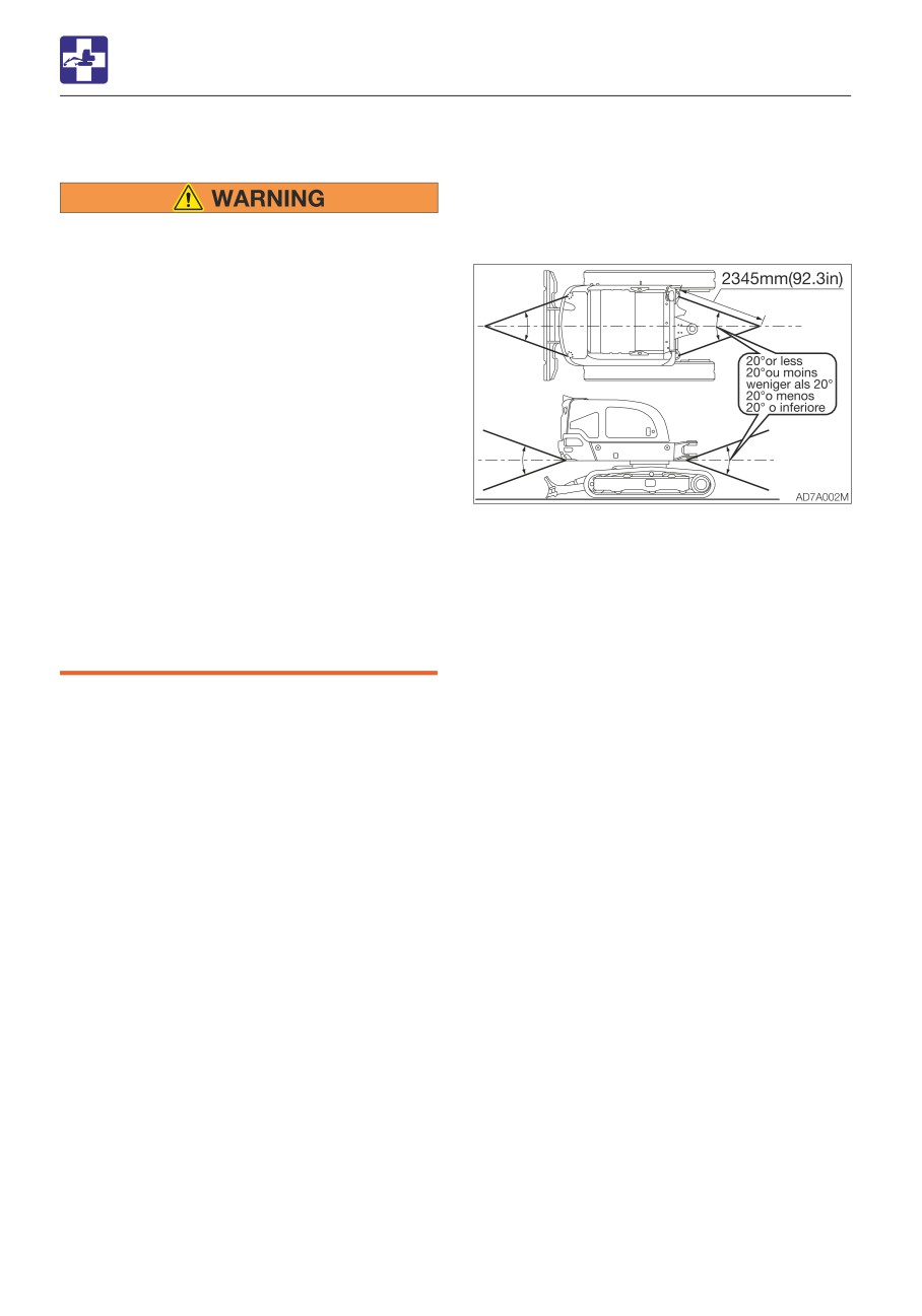
3. Make sure that the wire rope is at a cone
rope while towing.
angle of 20° or less to the travel frame.
4. Move the machine to tension the wire
IMPORTANT: Do not tow a machine if its
rope.
engine does not start or if the machine
5. Move the machine at a low speed of 2
does not run. Doing so could damage the
km/h (1.24 mph) or less to a place
machine being towed.
(convenient location for repair) a short
IMPORTANT: Be sure to follow the steps
distance from the site.
below closely when using the towing hole
to tow. Failure to heed even one of the
steps may cause damage to the towing
hole or other parts of the frame.
6-18
TROUBLESHOOTING
IF THE CAB OR CANOPY IS DAMAGED
IF THE CAB OR CANOPY IS
DAMAGED
Immediately replace the damaged cab or
canopy. Serious injury or death may occur
if the machine is operated with damaged
cab/canopy.
Do not operate the machine until the
replacement is complete. Do not try to
repair the damaged cab or canopy by
welding. Doing so could endanger the
safety of the cab/canopy.
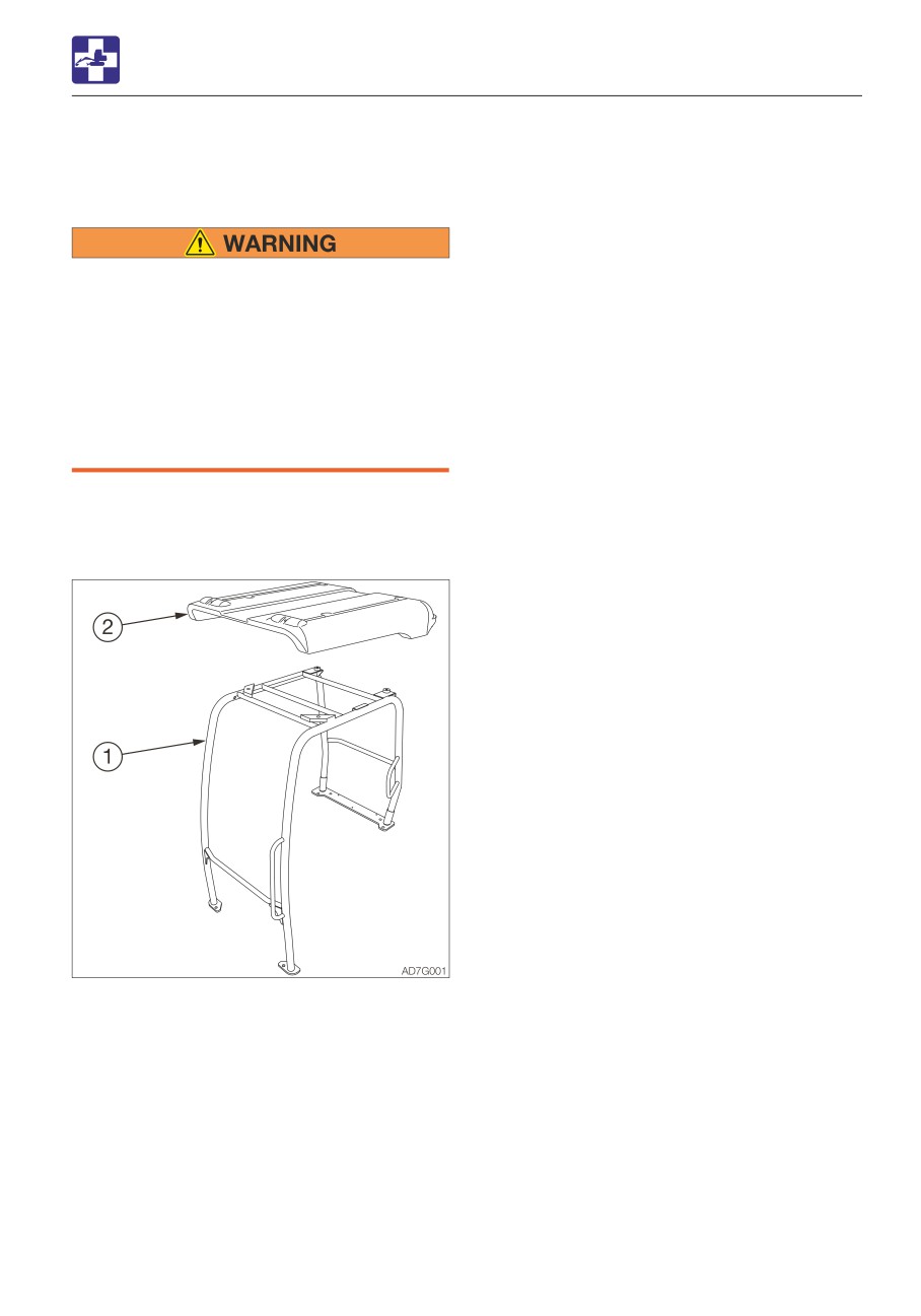
· Cab parts No. 03486-00028
· Canopy parts No.(1) 03484-00003
· Canopy parts No.(2) 03484-00027
6-19
SPECIFICATIONS
7-1
SPECIFICATIONS
BASIC SPECIFICATIONS
BASIC SPECIFICATIONS
Type
Cab
Canopy
MASS
Operating mass
kg (lb)
Rubber crawlers
2400 (5290)
2265 (4995)
PERFORMANCE
Heaped
0.064
(2.26)
Bucket capacity
m3 (cu. ft.)
(Standard bucket)
Struck
0.047
(1.66)
Slew speed
min-1 (rpm)
9.7
(9.7)
1st
2.5
(1.55)
Travel speed
km/h (mph)
Rubber crawlers
2nd
4.2
(2.61)
Gradeability
(degrees)
30
Ground pressure
kPa (psi)
Rubber crawlers
30.4
(4.41)
28.7
(4.16)
Sound power level
LWA 93
Noise level dB (A)
Emission sound pressure level at the
LpA 79
operator’s position (ISO 6396,2008:)
ENGINE
Manufacturer and model
Yanmar 3TNV82A
Net (ISO 14396)
kW/min-1 (hp/rpm)
16.5/2200 (22.1/2200)
Rated output
Net (ISO 9249/
kW/min-1 (hp/rpm)
15.8/2200 (21.2/2200)
SAEJ1349)
Displacement
ml (cu.in.)
1330 (81.2)
Amount of CO2 emission*
g/kWh
774
Starter
V-kW
12-1.7
Alternator
V-kW
12-0.48
Battery (IEC 60095-1)
V-A·h
12-58
CCA
A
490
*: The amount of CO2 emission refers to the value obtained by testing the parent engine
representing the engine type (engine family member) being used; it shall not guarantee the
performance of the machine.
7-2