Takeuchi Mini Excavator TB215R (No.215000003~). Operator's Manual - page 14
 

  Index      Manuals     Takeuchi Mini Excavator TB215R (No.215000003~). Operator's Manual


Search            copyright infringement  


Content      ..     12      13      14      15     ..


Takeuchi Mini Excavator TB215R (No.215000003~). Operator's Manual - page 14


DISASSEMBLY AND ASSEMBLY

SLEW MOTOR

9

4

SLEW MOTOR

4N0AX00

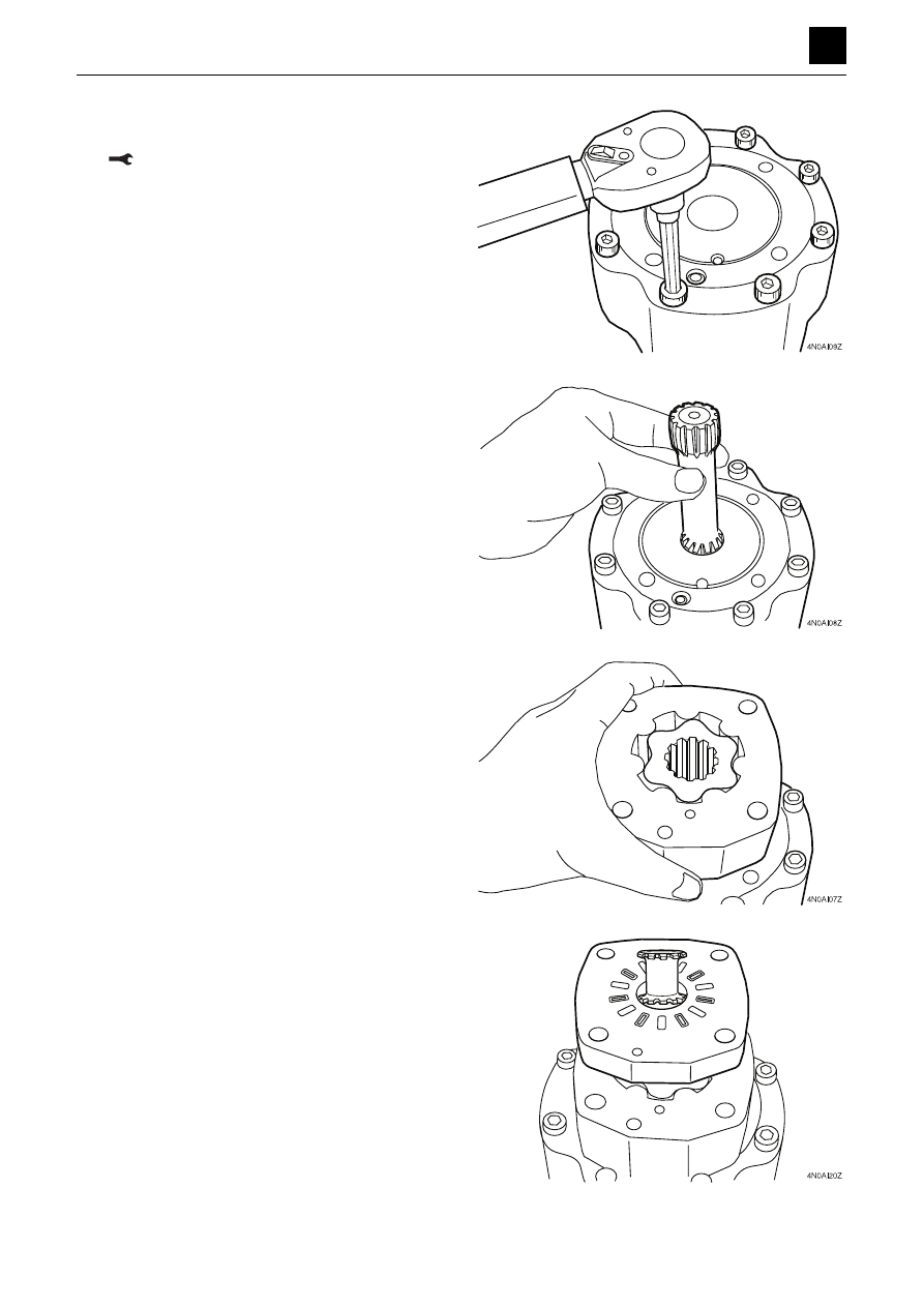
9. Tighten the socket bolts.

• Apply Loctite #242 to the socket bolt.


Bolt: 34.3 N·m (29.3 ft.-lb)

10. Insert the drive gear. 

11. Fit the O-rings (large and small) to the flange mount-

ing, and attach them to the gerolor.

• When installing, be sure to align the flange mount-

ing with the gerolor drain hole.

12. Insert the valve drive into the gerolor.

13. Fit the O-rings (large and small) to the valve plate,

and insert them into the gerolor.

• When inserting, be sure to align the valve plate

with the gerolor drain hole.

DISASSEMBLY AND ASSEMBLY

SLEW MOTOR

10

4

SLEW MOTOR

4N0AX00

14. Attach the valve.

Important: The valve timing determines the rotation direc-
tion of the motor. Carefully attach the valve by referring to
the figure below.

15. Insert the plug, spring, and ball into the valve hous-

ing.
 

Plug: 58.8 N·m (43.4 ft.-lb)

16. Insert the spring and pin into the valve housing.

DISASSEMBLY AND ASSEMBLY

SLEW MOTOR

11

4

SLEW MOTOR

4N0AX00

17. Fit the inner face seal (11) and the outer face seal

(12) to the balancing plate (5).

18. Align the notch on the balancing plate (5) with the

pin, and attach the plate to the valve housing (13).

19. Attach the O-rings (large and small) to the housing.

20. Attach the valve housing to the valve while prevent-

ing the balancing plate from becoming disconnect-
ed by pushing against it with a thin bar, such as a
screwdriver, inserted from the port.

• When attaching, be sure to align the drain hole on

the valve housing with the drain hole on the valve
plate.

21. Align the bolt holes, and tighten the bolts.

• Apply Loctite #242 to the bolt threads.

Bolt: 53 N·m (39.1 ft.-lb)

DISASSEMBLY AND ASSEMBLY

SLEW MOTOR

12

4

SLEW MOTOR

4N0AX00

22. Insert the O-ring into the housing.

23. Attach the brake valve to the hydraulic motor, and

tighten with socket bolts.

Socket bolt: 54 N·m (39.3 ft.-lb)

DISASSEMBLY AND ASSEMBLY

SLEW MOTOR

13

4

SLEW MOTOR

4N0AX00

Inspection and adjustments

Checking the parts

Brake valve

Hydraulic motor

Part

Criteria

Action

Body

• If there is severe damage to sliding parts or excessive surface rough-

ness

• Replace

• If there is damage, etc. that allows oil leakages to occur

• Replace

Relief valve as-
sembly

• If there are abnormal drops in the set pressure

• Replace

• If there is vibration due to the set pressure being unstable

• Replace

• If there is increased leakage due to faulty seating

• Replace

Spring

• If there is a high degree of breakage or deformation

• Replace

Steel ball

• If there is damage, etc. that allows oil leakages to occur

• Replace

Part

Criteria

Action

Shaft

• If there is pitting, abrasion, etc. occurring on the surfaces of the gear

teeth

• Replace

• If there is flaking or pitting occurring on rolling surfaces

• Replace

Ball bearing

• If there are abnormalities occurring in rotation (abnormal noise gen-

erated, rotation not smooth, etc.)

• Replace

• If there is flaking, abrasion, etc. occurring on rolling surfaces

• Replace

Valve drive

• If there is pitting, abrasion, etc. occurring on the surfaces of the gear

teeth

• Replace

Drive gear

• If there is excessive wear on the spline

• Replace

Inner face seal

• If there is damage, etc. that allows oil leakages to occur

• Replace

Outer face seal

Steel ball

• If there is damage, etc. that allows oil leakages to occur

• Replace

Gerolor

• If there is pitting, abrasion, etc. occurring on the surface of the gear

teeth

• Replace

• If there are abnormalities occurring in rotation (abnormal noise gen-

erated, rotation not smooth, etc.)

• Replace

DISASSEMBLY AND ASSEMBLY

SWIVEL JOINT

1

4

SWIVEL JOINT

4O0AX00

SWIVEL JOINT 

CONSTRUCTION

  1. Slipper Seal
  2. O-ring
  3. O-ring
  4. O-ring
  5. O-ring
  6. Backup Ring
  7. Dust Seal
  8. Cover

  9. Cover
10. Spring
11. O-ring
12. O-ring
13. Backup Ring
14. Washer
15. Hub
16. Shaft

17. Flange
18. Thrust Ring
19. Snap Ring
20. Selector Assembly
21. Body
22. Spool

DISASSEMBLY AND ASSEMBLY

SWIVEL JOINT

2

4

SWIVEL JOINT

4O0AX00

DISASSEMBLY AND ASSEMBLY

General Cautions

Carry out disassembly and assembly operations in

a clean place and provide clean containers to place

the disassembled parts in.

Before  disassembly,  clean  around  the  ports  and

remove  the  paint  from  each  joint  using  a  wire

brush.

Clean all disassembled parts in cleaning solvent.

Use a lint free cloth, or air dry the parts.

Make match marks on each part so that they will be

assembled in the same positions when assembled.

Replace  all  seals  with  new  ones  each  time  the

hydraulic units is disassembled.

Check each part to make sure there is no abnormal

wear or seizing and use sandpaper, etc. to remove

any burrs, sharp edges, etc.

Do not turn adjusting screws if not required.

Apply hydraulic oil to sliding surfaces and apply a

thin coating of grease to seals when assembling

them.

The following describes the disassembly procedure.

For assembly, follow the disassembly procedure in

the reverse order.

Disassembly

Selector

1. Remove the cap screw, and take off the selector

and O-ring from the shaft of the swivel joint.

Cap Screw: 6.9 N·m(5.1 ft-lb.)

2. Loosen the cap screw and remove the cover (1).

Then remove the spring (2) and washer (3) from

the spool (4).

3. Remove the spool (4) from the body.

4. Loosen the cap screw and remove the cover (5),

backup ring (6) and O-ring (7).

When assembling, confirm that the spool moves

smoothly.

Cap Screw: 6.9 N·m(5.1 ft-lb.)

5. Remove the O-ring (8) from the body assembly.

C4D705

1

2

3

8

8

4

7

6

5

DISASSEMBLY AND ASSEMBLY

SWIVEL JOINT

3

4

SWIVEL JOINT

4O0AX00

Swivel Joint

1. Take out the bolts and remove the spring washers,

then remove the flange (1) from the hub.

Bolt: 27.5 N·m

During assembly, place a pipe on the stopper
pin of the shaft and check if the shaft rotates.

2. Remove the O-ring (2), snap ring (3) and thrust

ring (4).

During assembly, make sure the snap ring fist
securely in the groove.

3. Remove the shaft (5) from the hub.

Place a knock pin (6) against the shaft end and
tap with a hammer. Select a knock pin (6) made
of copper or plastic, etc..

During assembly, apply a thin coat of hydrau-
lic oil to the outer circumference of the shaft.

4. Remove the dust seal from the shaft.

Cap Screw: 6.9 N·m(5.1 ft-lb.)

DISASSEMBLY AND ASSEMBLY

SWIVEL JOINT

4

4

SWIVEL JOINT

4O0AX00

5. Remove the seals from the inside diameter of the

hub.

Check the positions of the seals in the struc-
tural drawing.

Use an O-ring tooth or eyeleteer with a sharp
point on the end, etc.

Do not deform or bend the slipper seal strongly
in any one place.

During assembly, O-rings should not be twisted
when they are fitted in place.

DISASSEMBLY AND ASSEMBLY

SWIVEL JOINT

6

4

SWIVEL JOINT

4O0AX00

Inspection after assembly

After assembly, perform an oil leak test on each circuit
using the apparatus shown in the figure.

1. Connect the pipe (3) from the hydraulic pump (2) to

the shaft (1) side port.

2. Connect the pressure gauge (5) to the hub (4) side.

•  Increase the pressure gradually to 20.6 MPa (2900PSI)while

adjusting the relief valve 

(6).


Perform

 the leak test

for one minute.

Open the neighboring ports on both sides and vi-
sually check for leaks from the ports.

• Perform a color check to detect external leaks.

4O0AF08Z 

1

3

4

5

6

2

TROUBLESHOOTING

ABOUT THE TROUBLESHOOTING SECTION

1

5

ABOUT THE TROUBLESHOOTING SECTION

5A0BQ00

ABOUT THE TROUBLESHOOTING SECTION

This “Troubleshooting” section describes the fault diagnosis and corrective actions mainly for hydraulic systems. The
cause of the problem can be investigated by following the steps in the chart shown at the beginning of each item.

Notes on troubleshooting and servicing

1. Do not disassemble the faulty part without first investigating a, b, and c below.

a. Ask the user the following questions.

• The situation when the fault occurred.
• Any abnormalities or changes before the fault occurred.
• Any faulty parts other than the part in question.
• Any identical failure in the past

b. Drive the machine yourself and confirm the faulty condition.

• Determine if it is really faulty by referring to the performance criteria. Note that such determination may differ

depending on the person.

Important
By operating the user’s machine, you could make a bad situation worse. Therefore, before driving the machine,
always ask the user’s permission to do so.

c. Determine the cause of trouble based on the information obtained from the user and by driving the machine your-

self. Also remember that once the machine has been disassembled, it is almost impossible to reproduce the con-
ditions of the trouble, and so there will be no second chance to find out the true cause. Therefore be sure to find
the true cause of the trouble before attempting disassembly.

2. When multiple causes are suspected, start with the simplest one.

3. Think why the trouble occurred and try to correct the root cause of the problem.

1

5

Overall machine

TroubleshooTing

5b0AX00

overAll mAchine

Overall machine

No operation is possible.

1

check  the  hydraulic  oil 
level

insufficient

Add hydraulic oil.

sufficient

2

check 

the 

hydraulic 

pump

Faulty

• Repair  or  replace  the  hy

-

draulic pump.

• Replace the coupling.

  1.  check the hydraulic oil level.

    check the hydraulic oil tank level.

 “4.  Disassembly  and  assembly,  hydraulic  oil 

tank”

    When adding, use the same brand of oil currently being 

used.

 “2. service data, Fuel and lubricant table”

  2.  check the hydraulic pump.

 •  Check the discharge pressure of the pumps P1 and 

P2 (piston pumps).

 “2. Service data, Performance criteria”
 “5. Troubleshooting, Piston pump”

 •  Check the pumps P3 and P4 (gear pumps).

 “2. Service data, Performance criteria”
 “5. Troubleshooting, Piston pump”

2DAA01Z

P1

P2

P3

P4

2

5

Overall machine

TroubleshooTing

5b0AX00

overAll mAchine

All systems working, but insufficient force.

1

check  the  hydraulic  oil 
level

insufficient

2

Add hydraulic oil.

sufficient

3

Abnormal  noise  from  the 
piston pump

Yes

suction line faulty

Replace the seal tape, O-ring 

and hose.

no

Frothing in the tank

Action  appropriate  to  the 

cause of the frothing.

4

check  the  main  relief 
valve

Faulty

repair or replace the main re-
lief valve.

normal

5

Piston pump is faulty

repair  or  replace  the  faulty 
piston pump.

  1.  check the hydraulic oil level.

 “4.  Disassembly  and  assembly,  hydraulic  oil 

tank”

  2.  add hydraulic oil.

 “no operation is possible, 1. check the hydraulic 

oil level.”

  3.  abnormal noise from the piston pump.

    The  noise  is  likely  to  be  caused  by  cavitation  in  the 

pump, due to a faulty suction line. check the follow-

ing.
a. The line for sucking the hydraulic oil

 •  Apply grease or oil on the suspected faulty sec

-

tions and check for a change (check if air is being 
sucked).

b. Clogging in the suction filter
c. Pressurize the hydraulic tank.

 “4.  Disassembly  and  assembly,  hydraulic 

tank”

3

5

Overall machine

TroubleshooTing

5b0AX00

overAll mAchine

  4.  check the main relief valve.

    measure the relief pressure of the main relief valve.

 •  If  the  measured  value  is  within  specifications,  the 

valve is normal.

 “2. Service data, Performance criteria”

   if the pressure of the main relief valve is low, adjust 

it to the set pressure by gradually tightening the set

-

screw.

 •  If the pressure does not increase after tightening the 

setscrew by 1/4 turn, the relief valve is faulty.

  5.  Piston pump is faulty.

    if the inside of the pump is excessively worn or dam-

aged, it is likely that metal pieces are in the hydraulic 
oil. If this is the case, do the following.
 •  Replace the elements of the line filter and the spin 

filter.

 •  Replace the hydraulic oil or perform flushing.  
 •  When replacing the hydraulic oil, clean the tank and 

the suction strainer.

 “4. Disassembly and assembly, Piston pump”

4

5

Overall machine

TroubleshooTing

5b0AX00

overAll mAchine

Boom, bucket, slew and arm fail to move or are too slow.

1

Check  the  gear  pump 
(P4)

Faulty

• Repair  or  replace  the  gear 

pump

• Replace the coupling

normal

2

check the fuse

Faulty

replace the fuse

normal

3

check the limit switch

Faulty

Adjust  or  replace  the  limit 
switch

normal

4

check the lever lock sole-
noid valve

Faulty

repair  or  replace  the  lever 
lock solenoid valve

normal

5

check  the  pilot  relief 
valve

Faulty

repair or replace the pilot re-
lief valve

normal

6

check the pilot valve

Faulty

repair  or  replace  the  pilot 
valve

  1.  check the gear pump (P4)

    Check the gear pump (P4) (1) which supplies hydraulic 

pressure to the pilot valve.

 •  The inspection procedure is the same as for the pis

-

ton.

 “2. Service data, Performance criteria”
 “5. Troubleshooting, Piston pump”

    Also, check the line filter for clogging, and clean it as 

necessary.

%$,=


Content      ..     12      13      14      15     ..