Takeuchi Mini Excavator TB215R (No.215000003~). Operator's Manual - page 12
 

  Index      Manuals     Takeuchi Mini Excavator TB215R (No.215000003~). Operator's Manual


Search            copyright infringement  


Content      ..     10      11      12      13     ..


Takeuchi Mini Excavator TB215R (No.215000003~). Operator's Manual - page 12


8

4

Cylinders

Disassembly anD assembly

4l0aX00

CylinDers

26

4LAA21Z

4LAA22Z

4LAA23Z

27

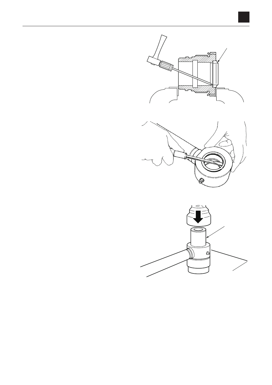
  4.  Remove the dust seal (26).

 •  Tap  alternately  on  several  points  around  the  inner 

circumference of the metal ring, gradually pushing 
the seal out of the groove.

Clevis

  1.  remove the dust seals from the tube and the piston 

rod clevis.

  2.  remove the bushing.

 •  Pull out the bushing by using a press and the sup

-

porting metal (27)

9

4

Cylinders

Disassembly anD assembly

4l0aX00

CylinDers

4LAA24Z

B

28

29

4LAA25Z

Assembly

Clevis

  1.  Using the installation jig B, press fit the bushings (28) 

into the piston rod and tube.

  2.  install  the  dust  seal  by  using  the  supporting  metal 

(29).

Rod cover

  1.  install the rod packing.

a. Install the backup ring (16). (Bucket cylinder, Swing 

cylinder)

b. Install the rod packing (15).

<Only for swing cylinder>

  2.  install the cushion ring.

a. Install the cushion ring (12).
b. Install the spacer (14).
c. Install the stopper (13).

10

4

Cylinders

Disassembly anD assembly

4l0aX00

CylinDers

  3.  Install the dust seal (26).

 •  For a dust seal with a metal ring around its perim

-

eter, use a supporting metal (30) for installation. 

  4.  Install  the  backup  ring  (22)  and  the  O-rings  (20)  and 

(21).
 •  Make sure that the cut portion of the backup ring 

does not get out of place.

Piston

  1.  install the piston packing on the piston.

a. Install the O-ring (34).

 •  If the O-ring is twisted after fitted, correct it.

b. Cover  the  piston  with  the  sliding  jig  C,  and  then, 

using the fitting jig D, quickly insert the slipper ring 
(35).

26

30

4LAA26Z

/$&=

4LAA29Z

34

35

4LAA30Z

C

D

11

4

Cylinders

Disassembly anD assembly

4l0aX00

CylinDers

c. Since the slipper ring (35) is extended when it is in

-

stalled, correct it using the corrective jig E.

  2.  Install the wear ring (10).

 •  Spread the wear ring (10) just enough so that it can 

be installed on the piston in axial direction.

Piston rod assembly

  1.  install the rod cover assembly on the piston rod.

<Only for swing cylinder>

  2.  install the cushion bearing on the piston rod.

 •  The cushion bearing must be installed in the correct 

direction.  Place  the  worked  surface  portion  facing 
the correct side as shown in the figure.

E

34

35

4LAA31Z

4LAA16Z

10

11

4LAA13Z

12

4

Cylinders

Disassembly anD assembly

4l0aX00

CylinDers

3.  install the piston on the piston rod.

<Only for boom cylinder (a to d)>

a. Place  the  cushion  seal  (7)  in  the  groove  with  the 

seal’s slitted portion facing the thread side. 

b. Install the cushion bearing (6) with its worked sur

-

face portion facing the correct side as shown in the 
figure.

c. Install the stopper (5) in the groove.
d. Push  the  cushion  bearing  (6)  fully  to  the  stopper 

side, and then install the snap ring.

e. Install the piston (3) and tighten it.
f.  Insert the ball (2), tighten the set screw (1) and caulk 

at two points with a punch.

 Piston, setscrew

Cylinder assembly

  1.  secure the tube in a level position, and insert the piston 

rod assembly into the tube.

 •  When  inserting,  align  the  center  of  the  piston  rod 

with  the  center  of  the  tube.  insert  the  assembly 
straight so as not to damage the seal.

  2.  Tighten the rod cover.

 rod cover

/$)=

$

Cylinders

Piston

(N·m)

set screw

(N·m)

boom

479 (353 ft-lb.)

6.8 (5.0 ft-lb.)

arm

479 (353 ft-lb.)

6.8 (5.0 ft-lb.)

bucket

245 (180 ft-lb.)

6.8 (5.0 ft-lb.)

blade

365 (269 ft-lb.)

6.8 (5.0 ft-lb.)

swing

479 (353 ft-lb.)

6.8 (5.0 ft-lb.)

4LAA35Z

4LAA36Z

Cylinders

rod cover

(N·m)

boom

304 (224 ft-lb.)

arm

304 (224 ft-lb.)

bucket

255 (188 ft-lb.)

blade

304 (224 ft-lb.)

swing

304 (224 ft-lb.)

13

4

Cylinders

Disassembly anD assembly

4l0aX00

CylinDers

  3.  bend down the lock rib on the tube and fit it into the 

notch of the rod cover to lock it.

14

4

Cylinders

Disassembly anD assembly

4l0aX00

CylinDers

inspection and adjustment

Inspection after disassembly

Clean each part thoroughly with cleaning oil, then carry out 
the following checks. When a cylinder has been disassem-
bled, replace all the seals with new ones.

  1.  Piston rod

 •  Replace the rod if there are cracks.
 •  If the threads are damaged, repair them or replace 

the rod.

 •  If  the  plating  layer  of  the  plated  portion  is  broken, 

rusted or scratched, replace the rod.

 •  If the rod is bent more than the limit of 1 mm (0.04 

in.) in 1 m (3.3 ft.), replace it. (For the measurement 

method, refer to the figure on the right.)

 •  If the inner diameter of the clevis bushing is worn, 

replace the bushing.

    Measuring the bend

a. support the portion of the rod with the same diam-

eter at both ends on V-blocks.

b. set  a  dial  gauge  at  the  center  between  the  two 

blocks.

c. Rotate the rod and take a reading of the maximum 

and minimum run-out indicated by the dial gauge. if 
the bending of the rod is within the above limit, yet is 
bent a lot in a small distance so that it will not move 

smoothly,  replace  the  rod  if  it  makes  a  squeaking 

sound in the operation test after reassembly or if it 
catches during movement.

  2.  Tube

 •  If there are cracks in the welded portion, replace the 

tube.

 •  Replace the tube if the inside surface is scratched or 

if it leaks hydraulic oil.

 •  If the inner diameter of the clevis bushing is worn, 

replace the bushing.

  3.  rod cover

 •  If the bushing inner diameter is worn and the clear

-

ance  with  the  piston  rod  is  greater  than  0.25  mm 

(0.0098 in.), replace the bushing.

 •  If the inside surface of the bushing is scratched, and 

the scratches are deeper than the depth of the coat-
ing layer, replace the bushing.

4LAA37Z

1/2

15

4

Cylinders

Disassembly anD assembly

4l0aX00

CylinDers

inspection after assembly

No load operation test

  1.  Place the cylinder in a horizontal position with no load.
  2.  apply gentle pressure alternately to the ports at both 

ends, operating the piston rod 5 or 6 times.

  3.  make sure there is no abnormality in the operating con-

dition.

Leak test

External leak

  1.  apply test pressure for 3 minutes each to the retraction 

side and the extension side.

  2.  Make sure there are no abnormalities such as external 

leakage or permanent deformation, etc. in the rod seal, 
the rod cover mount, or in any welded portion.

Internal leak

  1.  Disconnect the extension side hose.

  2.  apply  test  pressure  to  the  retraction  side  for  3  min-

utes.

  3.  measure  the  amount  of  oil  that  has  leaked  from  the 

extension side.
 •  The amount of leakage should be 1 mL (0.034 fl.oz) 

/3 min or less.

Bleeding air from the hydraulic cylinder

bleed  the  air  out  of  the  cylinder  when  the  cylinder  is  re-
moved or when the hydraulic piping, etc. is disconnected.

  1.  Start the engine and let it idle for approximately 5 min

-

utes.

  2.  With the engine running at slow speed, extend and re

-

tract the cylinder 4 or 5 times.

 •  Move the piston rod to a position 100 mm (3.94 in.) 

before  the  end  of  the  stroke,  being  careful  not  to 
relieve air.

  3.  With the engine at top speed, repeat the operation in 

(2), then with the engine running at slow speed, move 

the piston rod to the stroke end to relieve air.

4LAA38Z

4LAA39Z

DISASSEMBLY AND ASSEMBLY

TRAVEL MOTOR

1

4

TRAVEL MOTOR

4M0AX00

TRAVEL MOTOR

Construction

Hydraulic motor

1. Valve body

12. Spring

23. Friction disc

2. Flange holder

13. Retainer

24. Center disc

3. Shaft

14. Bearing

25. Oil seal

4. Cylinder block

15. Bearing

26. Spring pin

5. Valve plate

16. Break piston

27. Ball

6. Piston

17. Spring

28. Pin

7. Shoe

18. Snap ring

29. 2nd-speed piston

8. Shoe holder

19. O-ring

30. Backup ring

9. Guide

20. O-ring

31. Backup ring

10. Swash plate

21. O-ring

32. Plug

11. Pin

22. O-ring

DISASSEMBLY AND ASSEMBLY

TRAVEL MOTOR

2

4

TRAVEL MOTOR

4M0AX00

Reduction gears

1. Housing

11. Needle

21. Spring pin

2. Cover

12. Needle

22. O-ring

3. Carrier 2

13. Floating seal

23. O-ring

4. Planet gear B1

14. O-ring

24. Plug

5. Planet gear B2

15. Bearing

25. Thrust washer

6. Sun gear S1

16. Thrust washer

26. Plug

7. Pin

17. Snap ring

27. O-ring

8. Thrust washer

18. Snap ring

28. Ring

9. Seal ring

19. Snap ring

29. Ring

10. Snap ring

20. Snap ring

DISASSEMBLY AND ASSEMBLY

TRAVEL MOTOR

3

4

TRAVEL MOTOR

4M0AX00

Valves

1. Spool

7. Shuttle spool

13. Plug

2. Check valve

8. Spring

14. O-ring

3. Spring guide

9. Spring

15. O-ring

4. Spool

10. Plug

16. O-ring

5. Spool

11. Plug

17. O-ring

6. Spool

12. Plug

18. O-ring

DISASSEMBLY AND ASSEMBLY

TRAVEL MOTOR

4

4

TRAVEL MOTOR

4M0AX00

Assembly

The assembly procedures are given below. For disas-
sembly, follow the same procedures as for assembly but
in the reverse order by referring to the construction dia-
gram.

Counter balance valve and hydraulic motor

1. Secure the valve body in a vise, and insert the spool

into the valve body.

• Insert an aluminum plate or the like between the

motor and the vise to prevent the outer surface of
the valve body from becoming damaged.

• Do not further disassemble the spool assembly.

2. Attach the rings (1) and springs (2) to both ends of

the spool.

3. Attach the O-rings to the plugs, and tighten the plugs

on both ends of the body.

Plug: 127 to 167 N·m (93.7 to 123.2 ft.-lb)

DISASSEMBLY AND ASSEMBLY

TRAVEL MOTOR

5

4

TRAVEL MOTOR

4M0AX00

4. Insert the 2-speed spool (4) and spring (5) into the

valve body. 

5. Attach the O-rings to the plugs, and tighten the plugs

on each end of the body.

Plug: 46 to 51 N·m (33.9 to 37.6 ft.-lb)

6. Insert the shuttle and the needles (on both sides).

7. Attach the O-rings to the plugs, and tighten the plugs

on both ends of the body.

Plug: 59 N·m (43.5 ft.-lb)

DISASSEMBLY AND ASSEMBLY

TRAVEL MOTOR

6

4

TRAVEL MOTOR

4M0AX00

8. Attach the O-rings (large and small) to the valve

body.

9. Press-fit the oil seal into the flange holder.

• Do not disassemble the oil seal unless necessary.

Add grease between the lips of the oil seal.

10. Insert the pin. 

11. Insert the 2nd-speed piston.

DISASSEMBLY AND ASSEMBLY

TRAVEL MOTOR

7

4

TRAVEL MOTOR

4M0AX00

12. Insert the shaft into the flange holder.

• The bearing is press-fitted and thus cannot be

disassembled.

• Be careful not to damage the oil seal with the

shaft.

13. Place the balls and the swash plate in the flange

holder.

• Apply hydraulic oil to the sliding surfaces of the

swash plate.

14. Mount the retainer (6), spring (8), and retainer (7) on

the cylinder block, and secure the parts in place with
the snap ring (9).

15. Insert the 3 pins (10) into the cylinder block.

DISASSEMBLY AND ASSEMBLY

TRAVEL MOTOR

8

4

TRAVEL MOTOR

4M0AX00

16. Insert the piston (12) and guide (13) into the shoe

holder (11) to form the shoe holder assembly.

17. Place the shoe holder assembly into the cylinder

block to form the cylinder block assembly.

18. Insert the cylinder block assembly into the flange

holder.

• Insert the cylinder block assembly in such a man-

ner that the shoe will touch the swash plate.

19. Install the friction disc (14) in the groove on the cylin-

der block. 


Content      ..     10      11      12      13     ..