Takeuchi Mini Excavator TB215R (No.215000003~). Operator's Manual - page 10
 

  Index      Manuals     Takeuchi Mini Excavator TB215R (No.215000003~). Operator's Manual


Search            copyright infringement  


Content      ..     8      9      10      11     ..


Takeuchi Mini Excavator TB215R (No.215000003~). Operator's Manual - page 10


11

4

Control valve

Disassembly anD assembly

Control valve

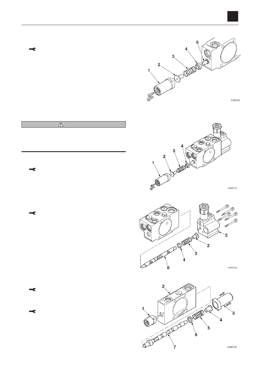
Pilot operated section

1.  remove  the  cap  screws  and  cover  (1),  and  then  re-

move the o-ring from the cover (1).

 Cap screw: 7.3 n·m (5.4 ft-lb.)

2.  remove  the  spring  holder  (2),  spring  (3)  and  spring 

holder (4).

3.  remove the spool (5) from the housing.

 • Make sure to insert the spool in the correct direc

-

tion.

Boom section

 WARning

If the anti-drift valve is disassembled with the control 
valve  still  installed,  parts  may  be  ejected  due  to  the 
internal pressure. remove it after relieving the internal 
pressure by gradually loosening the cap screw.

1.  remove  the  cap  screws  and  cover  (1),  and  then  re-

move the o-ring from the cover.

 Cap screw: 7.3 n·m  (5.4 ft-lb.)

2.  remove  the  spring  holder  (2),  spring  (3)  and  spring

holder (4).

3.  take out the cap screws and housing (5), and then re-

move the o-ring from the housing.

 • Do not further disassemble the anti-drift valve.

 Cap screw: 9.3 n·m  (6.9 ft-lb.)

4.  remove  the  spring  holder  (2),  spring  (3)  and  spring

holder (4).

5.  remove the spool assembly (6) from the housing.

 • Make sure to insert the spool in the correct direc

-

tion.

Switch valve

1.  remove  the  cap  screws  and  cover  (1),  and  then  re-

move the o-ring from the cover (1).

 Cap screw: 7.3 n·m  (5.4 ft-lb.)

2.  remove  the  cap  screws  and  cover  (3),  and  then  re-

move the o-ring from the cover (3).

 Cap screw: 7.3 n·m  (5.4 ft-lb.)

3.  remove  the  spring  holder  (4),  spring  (5)  and  spring

holder (6).

4.  remove the spool (7) from the housing.

 • Be sure to insert the spool in the correct direction.

12

4

Control valve

Disassembly anD assembly

4J0aX00

Control valve

Main relief valve

1.  remove the plug (1) from the housing (2).

 Plug: 49 to 54 n·m (36.1 to 39.8 ft-lb.)

2.  remove the o-ring (3) from the plug (1).

3.  remove the sleeve (4) from the plug (1), and then re-

move the spring (5) and the main poppet (6) from the 
sleeve (4).

4.  remove the o-ring (7) and the backup ring (8) from the 

seat (9).

5.  remove the lock nut (10), the washer (11) and the set-

screw (12) from the plug (1), and then remove the o-
ring (13) from the setscrew (12).

 • When assembling, first install the setscrew (12), and

then  temporarily  fasten  the  lock  nut  (10)  to  adjust
the pressure before final tightening.

 lock nut: 27 to 32 n·m (19.9 to 23.6 ft-lb.)

6.  remove the spring (14) and the needle valve (15). 

13

4

Control valve

Disassembly anD assembly

4J0aX00

Control valve

Inspection and adjustment

Checking the parts

Parts

Judgment criteria

treatment

Housing, valve body

• Scratches, rust or corrosion on the parts sliding against the 

spool

• Scratches, rust or corrosion on the seal pocket part that 

the spool enters

• Scratches, rust or corrosion on the seal part on the port 

that is in contact with the o-ring

• Scratches,  rust  or  corrosion  on  the  seal  part  of  the  relief 

valve, etc.

• Other damage considered to impair normal functions

replace

replace

replace

replace

replace

spool

• Scratches on the sliding surface of outer circumference, on 

which the fingernails get caught

• Scratches  on  parts  that  slide  against  the  seals  at  both 

ends

• Spool does not move smoothly

replace

replace
repair or replace

load check valve

• Imperfect sealing due to damage to the valve or spring.
• Operates  smoothly  when  inserted  and  operated  in  the 

housing

repair or replace
normal

around the springs

• Rust,  corrosion,  deformation,  breakage  or  other  notable 

damage to the spring, holder or cover

replace

around the spool seal

• Oil leakage to the outside
• Rust, corrosion or deformation of the seal holder

repair or replace
repair or replace

main  relief  valve,  port  re-
lief  valve,  anti-cavitation 
valve

• External rust, damage
• Damage to valve seat contact surface
• Damage to poppet contact surface
• Abnormality in the spring
• O-rings, backup rings, seals

replace
replace
replace
replace
replace as a rule

adjusting the main relief valve pressure

 “2. service data, Performance criteria”

DISASSEMBLY AND ASSEMBLY

PILOT VALVE

1

4

PILOT VALVE

4K2AQ00

PILOT VALVE

Construction

1. Casing

7. Seal

13. Spring

2. Plate

8. O-ring

14. Spring

3. Spool

9. Spring seat

15. Spring

4. Plug

10. Spring seat

16. Joint

5. Push rod

11. Washer 2

17. Cam

6. Push rod

12. Spring

18. Adjusting nut

DISASSEMBLY AND ASSEMBLY

PILOT VALVE

2

4

PILOT VALVE

4K2AQ00

Special tools

Unit: mm

Installation jig A

Quantity: 1
Material A: S45C
Material B: SCM415N (case hardened)

Installation jig B

Quantity: 2
Material B: SCM415N (case hardened)

Disassembly and Assembly

The numbers in parentheses () listed after the names of
parts in this document match the numbers used in the
construction diagrams and parts lists.

General Precautions

• Perform disassembly and assembly work in a clean

place. Provide clean containers to hold parts during
disassembly.

• Clean around the ports before disassembly. Remove

paint around connectors with a wire brush.

• Clean the disassembled parts with wash oil.
• Put alignment marks on all parts to reassemble them in

the same positions.

• After each disassembly, replace all seals and apply a

thin layer of grease to them.

• Check each part for abnormal wear or seizing. Re-

move any burrs with sandpaper.

4KAC02Z 

ø29 

ø26.5 

23.5 

ø19 

50 

54 

13 

46 

25 

17 

69 

ø23 

ø27 

ø31 

+0.2 

16 

+0.2 

+0.013 

+0.028 

+0.015 

4KAC03Z 

0.5x15°

11.6 

C0.5 

C0.5 

R4.5 

±0.1 

6.5 

9.5 

12.5 

±0.1 

15.5 

R5.8 

R13 

±0.1 

DISASSEMBLY AND ASSEMBLY

PILOT VALVE

3

4

PILOT VALVE

4K2AQ00

Disassembly

1. Remove the adjusting nut (18) and remove the cam

(17) from the joint.

• Fasten the valve to the vice using copper or lead

sheet.

2. Remove the joint (16), and then remove the plate (2).

• Use the installation jigs A and B.

3. Take out the plugs (4) and remove the push rods (5)

(6) from the plugs (4).

• If it is hard to remove, use a flathead screwdriver.
• Be aware that the plugs may fly out due to the

spring force.


WARNING

The spring may fly out during disassembly. Refer to the
construction diagram and take precautions.

4K2AQ02Z

2

A

DISASSEMBLY AND ASSEMBLY

PILOT VALVE

4

4

PILOT VALVE

4K2AQ00

4. Remove the O-ring (8) and the seal (7) from the plug.

5. Remove the pressure reducing valves and springs

(12) (13) from the casing.

• Put alignment marks on the pressure reducing

valves and casing holes, to ensure the same po-
sition during reassembly.

6. Disassemble the pressure reducing valve.

a. Push in the spring seats (9) (10) to compress the

springs (14) (15). Move the spool (3) from the
small hole side to the large hole side of the spring
seat (9) (10).

• Do not push down the spring seat more than 6

mm.

7. Remove the spring seats (9) (10), springs (14) (15),

and washer 2 (11) from the spool (3).

DISASSEMBLY AND ASSEMBLY

PILOT VALVE

5

4

PILOT VALVE

4K2AQ00

Assembly

1. Assemble the pressure reducing valve.

a. Install washer 2 (11), the springs (14) (15), and

the spring seats (9) (10) onto the spool (3).

b. Push in the spring seats (9) (10) to compress the

springs (14) (15). Move the spool (3) from the
large hole side to the small hole side of the spring
seats (9) (10).

• Do not push down the spring seat more than 6

mm.

2. Install the springs (12) (13) and the pressure reduc-

ing valves.

• Install them in the locations where they were be-

fore disassembly.

3. Install the O-ring (8) and the seal (7) onto each plug

(4).

DISASSEMBLY AND ASSEMBLY

PILOT VALVE

6

4

PILOT VALVE

4K2AQ00

4. Install the push rod (5) or (6) into the plug (5).

• Apply hydraulic oil to the push rod.

5. Attach the plugs and plate (2) and install the (16)

joint.

• Use the installation jigs A and B to install the joint.

Joint: 47.1± 2.9 N·m

6. Install the cam (17) and the adjusting nut (18).

• Tighten the adjusting nut (18) to uniformly contact

all four push rods.

• When tightening the adjusting nut, do not move

the cam.

Adjusting nut: 68.6 ± 4.9 N·m

Grease the contact surfaces on the rotating part
of the joint, the disc, and the push rod.

5,6

7

4

4K2AQ11Z

4K2AQ02Z

2

A

DISASSEMBLY AND ASSEMBLY

PILOT VALVE

7

4

PILOT VALVE

4K2AQ00

Inspection and adjustment

Checking the parts

Part

Criteria

Action

O-ring

• Replace

Seal

• Replace

Spool

• Wear on the sliding surfaces is 10 μm or more than the non-sliding

surfaces.

• Scratches on the sliding surfaces.
• Spool does not move smoothly. 

• Replace

• Replace
• Replace

Push rod

• Tip is worn 1 mm or more
• Scratches on the sliding surfaces

• Replace
• Replace

Plug

• Imperfect sealing due to damage

• Repair or replace

Controls

• Looseness in the pin, shaft or joint of the controls results in 2 mm

play, or more.

• Wear of the pin, shaft or joint of the controls results in 2 mm play, or

more. 

• Tighten to the specified

torque

• Replace

Casing, port 
plate

• Scratches, rust, or corrosion at the parts in sliding contact with the

spool.

• Scratches, rust, or corrosion of the part of the seal in contact with the

O-ring

• Replace

• Repair or replace

DISASSEMBLY AND ASSEMBLY

PROPORTIONAL CONTROL SOLENOID VALVE

1

4

PROPORTIONAL CONTROL SOLENOID VALVE

4K4AQ00

PROPORTIONAL CONTROL SOLENOID VALVE

Construction

1. Proportional control solenoid

2. Bolt

DISASSEMBLY AND ASSEMBLY

PROPORTIONAL CONTROL SOLENOID VALVE

2

4

PROPORTIONAL CONTROL SOLENOID VALVE

4K4AQ00

Disassembly and Assembly

The numbers in parentheses () listed after the names of
parts in this document match the numbers used in the
construction diagrams and parts lists.

General Precautions

• Perform disassembly and assembly work in a clean

place. Provide clean containers to hold parts during
disassembly.

• Clean around the ports before disassembly. Remove

paint around connectors with a wire brush.

• Clean the disassembled parts with wash oil.
• Put alignment marks on all parts to reassemble them in

the same positions.

• After each disassembly, replace all seals and apply a

thin layer of grease to them.

• Check each part for abnormal wear or seizing. Re-

move any burrs with sandpaper.

• Do not move adjusting screws, unless absolutely nec-

essary.

Disassembly

1. Remove the bolts (2) and remove the proportional

control solenoid (1).

Bolt: 6.9 ± 1 N·m

Assembly

For assembly, reverse the disassembly procedure.

Inspection and adjustment

Checking the parts

Part

Criteria

Action

Coil assembly

• The solenoid is burned-out, short-circuited, or a wire is broken.
• Wiring short-circuit or a wire is broken

• Replace
• Replace

Body

• Scratches, rust, or corrosion at the parts in sliding contact with the

spool.

• Scratches, rust, or corrosion of the part of the seal in contact with the

O-ring.

• Other damage considered to impair the normal functions

• Replace

• Replace

• Replace

Spool

• Scratches on the outer circumference that easily catch a fingernail
• Movement is not smooth

• Replace
• Repair or replace

Spring

• Rust, corrosion, deformation, breakage, or other notable damage

• Replace

O-ring

• Replace

DISASSEMBLY AND ASSEMBLY

SOLENOID VALVE (3RD AUXILIARY LINE PIPING)

1

4

SOLENOID VALVE (3RD AUXILIARY LINE PIPING)

4K6AV01

SOLENOID VALVE (3RD AUXILIARY LINE PIPING)

Construction

1. Plug

5. Spring

2. Solenoid coil

6. Spool

3. O-ring

7. Body

4. O-ring

8. Cap screw

DISASSEMBLY AND ASSEMBLY

SOLENOID VALVE (3RD AUXILIARY LINE PIPING)

2

4

SOLENOID VALVE (3RD AUXILIARY LINE PIPING)

4K6AV01

Disassembly and Assembly

The numbers in parentheses () listed after the names of
parts in this document match the numbers used in the
construction diagrams and parts lists.

General Precautions

• Perform disassembly and assembly work in a clean

place. Provide clean containers to hold parts during
disassembly.

• Clean around the ports before disassembly. Remove

paint around connectors with a wire brush.

• Clean the disassembled parts with wash oil.
• Put alignment marks on all parts to reassemble them in

the same positions.

• After each disassembly, replace all seals and apply a

thin layer of grease to them.

• Check each part for abnormal wear or seizing. Re-

move any burrs with sandpaper.

• Do not move adjusting screws, unless absolutely nec-

essary.

Disassembly

1. Remove the cap screws (8) and remove the solenoid

coil (2).

• Put alignment marks on the solenoids and body,

to ensure the same position during reassembly.

• Take care not to let the push rods fall out.

Cap screw: 4.9 N·m (3.6 ft.-lb)

2. Remove the O-ring (4) from the solenoid coil (2).

3. Take out the plug (1) and remove the O-ring (3) from

the plug (1).

Plug: 23.5 N·m (17.3 ft.-lb)

4. Remove the spring (5) and the spool (6) from the

body (7).

• Record the spool and body hole positions to use

the same positions during re-assembly.

Assembly

For assembly, refer to the construction diagram and re-
verse the disassembly procedure.

DISASSEMBLY AND ASSEMBLY

SOLENOID VALVE (3RD AUXILIARY LINE PIPING)

3

4

SOLENOID VALVE (3RD AUXILIARY LINE PIPING)

4K6AV01

Inspection and adjustment

Checking the parts

Part

Criteria

Action

O-ring

• Replace

Seal

• Replace

Spool

• Wear on the sliding surfaces is 10 μm or more than the non-sliding

surfaces.

• Scratches on the sliding surfaces
• Spool does not move smoothly. 

• Replace

• Replace
• Replace

Push rod

• Tip is worn 1 mm or more
• Scratches on the sliding surfaces

• Replace
• Replace

Plug

• Imperfect sealing due to damage

• Repair or replace

Controls

• Looseness in the pin, shaft or joint of the controls results in 2 mm

play, or more.

• Wear of the pin, shaft or joint of the controls results in 2 mm play, or

more. 

• Tighten to the specified

torque

• Replace

Casing, port 
plate

• Scratches, rust, or corrosion at the parts in sliding contact with the

spool.

• Scratches, rust, or corrosion of the part of the seal in contact with the

O-ring

• Replace

• Repair or replace

1

4

SOLENOID VALVE (LEVER LOCK)

DISASSEMBLY AND ASSEMBLY

4K6AX002

SOLENOID VALVE (LEVER LOCK)

  1. Plunger
  2. Spring
  3. Plug
  4. Spring
  5. Spool
  7.  Adjust screw
  8. Cover
  9. Plug
10. Plunger
11. Spring
12. Solenoid
13. Body

15. Plug
16. Plug
17.  Cap screw
18.  Cap screw
19. Washer
20. Nut
22. O-ring
23. O-ring
24. O-ring
25. O-ring
26. O-ring

SOLENOID VALVE (LEVER LOCK)

Construction


Content      ..     8      9      10      11     ..