Takeuchi Mini Excavator TB215R (No.215000003~). Operator's Manual - page 8
 

  Index      Manuals     Takeuchi Mini Excavator TB215R (No.215000003~). Operator's Manual


Search            copyright infringement  


Content      ..     6      7      8      9     ..


Takeuchi Mini Excavator TB215R (No.215000003~). Operator's Manual - page 8


DISASSEMBLY AND ASSEMBLY

OPERATING DEVICE

6

4

OPERATING DEVICE

4F0AX00

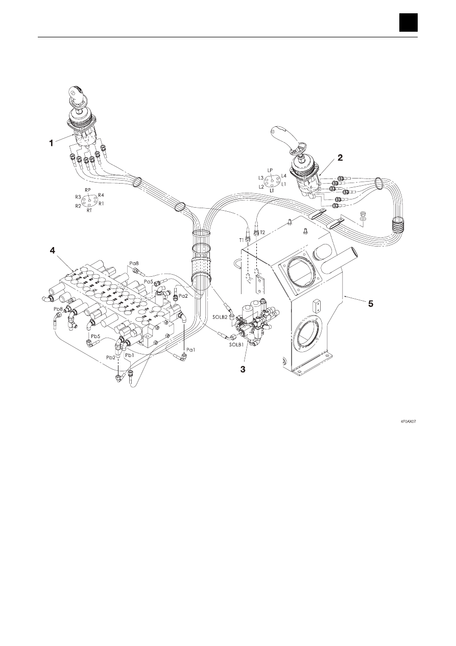
Hydraulic piping

DISASSEMBLY AND ASSEMBLY

OPERATING DEVICE

7

4

OPERATING DEVICE

4F0AX00

Table of Connections

1

R1 

 Pa1

4

1. Pilot valve (Right)

1

R2 

 Pb2

4

2. Pilot valve (Left)

1

R3 

 Pb1

4

3. Solenoid valve (Lever lock)

1

R4 

 Pa2

4

4. Control valve

1

RP 

 SOL B1

3

5. Hydraulic tank

1

RT 

 T1

5

2

L1 

 Pb8

4

2

L2 

 Pa5

4

2

L3 

 Pa8

4

2

L4 

 Pb5

4

2

LP 

 SOL B2

3

2

LT 

 T2

5

4

Pi2 

 Pb2

4

DISASSEMBLY AND ASSEMBLY

ATTACHMENTS

1

4

ATTACHMENTS

4G0AX001

ATTACHMENTS

Hoe attachment

Construction

DISASSEMBLY AND ASSEMBLY

ATTACHMENTS

2

4

ATTACHMENTS

4G0AX001

1

2nd auxiliary line piping

2

Do not overtighten the castle nut.
After tightening down the castle nut by hand, firmly tighten it down further until the tightening hole positions line up
properly and then secure the castle nut in place with a cotter pin.

3

After applying NEVER-SEEZ NS (Regular grade) or an equivalent anti-seizing lubricant, put the parts together.
• During assembly, grease the pins using lithium grease EP-2 supplied from the grease nipples.

1. Arm

9. Bucket cylinder

18. Pin

2. Link arm

10. Stop valve

19. Pin

3. Guide link R

11. Adapter

20. Pin

4. Guide link L

12. Shim (Selected usage)

21. Pin

5. Pin

13. Shim (Selected usage)

22. Pin

6. Pin

14. Boom

23. Shim (Selected usage)

7. Pin

15. Wire harness

24. Shim (Selected usage)

8. Pin

16. Working lamp

25. Shim (Selected usage)

8-1. Pin

17. Boom cylinder

26. Arm cylinder

DISASSEMBLY AND ASSEMBLY

ATTACHMENTS

3

4

ATTACHMENTS

4G0AX001

3

After applying NEVER-SEEZ NS (Regular grade) or an equivalent anti-seizing
lubricant, put the parts together.

4

Position with the grooved side facing upward.

27. Boom bracket

28. Pin

29. Pin

30. Pin

31. Pin

32. Swing cylinder

33. Washer (Selected usage)

DISASSEMBLY AND ASSEMBLY

ATTACHMENTS

4

4

ATTACHMENTS

4G0AX001

34. Blade

35. Blade cylinder

36. Pin

37. Plate R

38. Plate L

DISASSEMBLY AND ASSEMBLY

ATTACHMENTS

5

4

ATTACHMENTS

4G0AX001

Removing the hoe attachment

Important:

When tightening the lock bolt with a double nut, allow a
clearance of 0.5 mm to 1.0 mm (0.0197 in. to 0.0394
in.) between the nut and the lock collar.

Adjust the clearance for the pin connector to a width of
between 0.2 mm to 0.5 mm (0.0079 in. to 0.0197 in.)
using a shim.

Be sure to bleed the air from the cylinder before starting
operation for the first time after reassembling hydraulic
devices such as the hydraulic cylinder or hydraulic pip-
ing.

Grease the pins using lithium grease EP-2 supplied
from the grease nipples.

The numbers in parentheses, (), listed after the names of
parts throughout this document are used to refer to the
same parts as the numbers listed in the construction di-
agram and parts lists.

Removing the bucket

1. Orient the back of the bucket downward, and lower

the bucket all the way down to the ground.

2. Take out the bolts, and remove the pins.

3. Remove the bucket.

Installing the bucket

To install, follow the same procedures as for removal but
in the reverse order.
• Before starting to attach the bucket, place the O-ring

in the temporary placement position “A” in the outer
circumference of the bucket bushing, and move it to
the specified position “B” once attachment is complet-
ed.


WARNING

Be sure to release any residual pressure in the piping
before disconnecting the hydraulic hose.

Do not attempt to insert any fingers into the hole when
adjusting the pin hole position.

DISASSEMBLY AND ASSEMBLY

ATTACHMENTS

6

4

ATTACHMENTS

4G0AX001

Removing the link

Completely retract the bucket cylinder, and lower the tip
of the arm to the ground.

1. Take out the pin (5), and remove the link arm (2).

a. Guide links R (3) and L (4)

.......................Exercise caution as they may drop

b. Cylinder (9).....Place on a skid
c. Link arm (2) ....Suspend temporarily

2. Take out the pins (6) and (7), and remove the guide

links R (3) and L (4).

Installing the link

To install, follow the same procedures as for removal but
in the reverse order.

Removing the arm

1. Disconnect the hydraulic hoses from the bucket cyl-

inder (9).
Next, disconnect the hydraulic hoses from the auxil-
iary line ports.

2. Suspend the bucket cylinder (9) temporarily and

then pull out the pin and remove the bucket cylinder.

Bucket cylinder: 9 kg (20 lb)

3. Place a skid under the arm cylinder (26), and remove

the pin.

4. Take out the cotter pin, and remove the castle nut.

5. Suspend the arm (1) temporarily and then pull out the

pin and remove the arm.

Arm: 31 kg (68 lb)

Installing the arm

To install, follow the same procedures as for removal but
in the reverse order.

Important:
When securing the arm with the fixing pin A and castle nut
B, make sure not to tighten the castle nut B too much.
After tightening down the castle nut B by hand, firmly
tighten it down further until the tightening hole positions
for the fixing pin A and cotter pin for the castle nut B line
up properly.

DISASSEMBLY AND ASSEMBLY

ATTACHMENTS

7

4

ATTACHMENTS

4G0AX001

Removing the boom

Lower the tip of the boom all the way to the ground.

1. Disconnect the hydraulic hoses from the arm cylin-

der (26).

2. Suspend the arm cylinder (26) temporarily and then

pull out the pin and remove the arm cylinder.

Arm cylinder: 17 kg (37 lb)

3. Remove the boom cylinders.

a. Disconnect the hydraulic piping from the boom

cylinders (17). 

b. Suspend each boom cylinder (17) temporarily.
c. Push in the pin (22), and disconnect the head side

of the cylinder and lower the cylinder to the
ground.

d. Suspend the boom cylinder (17) temporarily, dis-

connect the rod side from the rod pin (21), and
raise the cylinder.

Boom cylinder: 20 kg (44 lb)

4. Disconnect the electrical wiring (15) to the boom light

from the wiring on the machine body side.

5. Disconnect the hydraulic hoses connected from the

machine body side from the pipes.

6. Hoist up the boom (14) temporarily and then pull out

the pin and remove the boom.

Boom: 57 kg (125 lb)

Installing the boom

To install, follow the same procedures as for removal but
in the reverse order.
During assembly, apply NEVER-SEEZ NS lubricant (an
anti-seizing lubricant) to the mounting pin holes for at-
taching the boom and then insert the pins into the appro-
priate holes.

DISASSEMBLY AND ASSEMBLY

ATTACHMENTS

8

4

ATTACHMENTS

4G0AX001

Removing the boom bracket

1. Take out the pin (31), and disconnect the swing cyl-

inder (32) from the boom bracket.

2. Suspend the boom bracket (27) temporarily and then

pull out the pins and remove the boom bracket.

• Be careful not to damage the hoses when working

with them.

Boom bracket: 30 kg (65 lb)

Installing the boom bracket

To install, follow the same procedures as for removal but
in the reverse order.
• During assembly, apply NEVER-SEEZ NS lubricant (an

anti-seizing lubricant) to the fixing pin holes on the
boom bracket and then insert the pins into the appro-
priate holes.

• Attach the washer (33) with the side with the grease

groove facing upward (toward the boom bracket side).

Removing the blade

Lower the blade all the way down to the ground.

1. Disconnect the hydraulic hoses from the blade cylin-

der (35).

2. Suspend the blade cylinder (35) temporarily and

then pull out the pins and remove the blade cylinder.

Blade cylinder: 11 kg (23 lb)

3. Suspend the blade (34) temporarily and then take

out the pins and remove the blade (34).

Blade: 50 kg (111 lb)

Installing the blade

To install, follow the same procedures as for removal but
in the reverse order.

DISASSEMBLY AND ASSEMBLY

HYDRAULIC TANK

1

4

HYDRAULIC TANK

4H0AX00

HYDRAULIC TANK

ThreeBond #1324

1. Hydraulic tank

6. Oil plug 

11. O-ring

2. Lid

7. Suction filter

12. Sight gauge

3. Pipe

8. Return filter

13. Drain plug

4. Bushing

9. O-ring

5. Plug

10. O-ring

DISASSEMBLY AND ASSEMBLY

HYDRAULIC TANK

2

4

HYDRAULIC TANK

4H0AX00

Removing the hydraulic tank

The numbers in parentheses ( ), listed after the names of
parts throughout this document are used to refer to the
same parts as the numbers listed in the construction di-
agram and parts lists.

1. Remove the covers from the perimeter around the

hydraulic tank. 

“Removing the covers”

2. Drain the hydraulic oil from the hydraulic tank (1).

a. Slowly loosen the oil plug (6) to release the inter-

nal pressure in the hydraulic tank.

b. Drain out the oil from the drain plug (13).

• Tank level capacity: 16.1 L (4.3 US gal.)

3. Disconnect the low-pressure hoses from the hydrau-

lic tank.

4. Disconnect the high-pressure hoses from the hy-

draulic tank.

• Attach an identification tag on each hoses to avoid

mixing them up during reassembly.

5. Take out the bolts holding the hydraulic tank in place,

and suspend the hydraulic tank and remove it.

Bolt: ThreeBond #1324
Bolt: 47 N·m (34.7 ft.-lb)
Hydraulic tank: 20 kg (43 lb)

Installing the hydraulic tank

For installation of the hydraulic tank, follow the same pro-
cedures as for removal but in the reverse order.

DISASSEMBLY AND ASSEMBLY

HYDRAULIC TANK

3

4

HYDRAULIC TANK

4H0AX00

Inspecting and refilling the oil in the hydraulic tank

Inspection

The oil level changes with the oil temperature. Inspect
the oil while maintaining the machine at the attitude for in-
specting the oil level.

Machine attitude for inspecting the hydraulic oil level

1. Start the engine, and run it at low speed.

2. Fully retract the arm cylinder and the bucket cylinder,

and then lower the bucket to the ground.

3. Stop the engine.

4. Inspect the oil level using the sight gauge (12).

When the oil temperature is about 20°C (68°F): The
level should be halfway between the upper limit (H)
and the lower limit (L). If it is below the lower limit (L),
replenish.
When the oil temperature is about 50 to 80°C (122 to
176°F): The level should be near the upper limit (H).

Refilling the oil
Important: Do not refill to above the (H) mark. Doing so
may cause damage to the hydraulic circuit or cause oil to
spurt out. If the oil level is accidentally filled to above the
(H) mark, stop the engine and allow the hydraulic oil to
cool down before draining off the excess oil from the drain
plug (13).
Important: Failure to pressurize the hydraulic tank may
cause the pump to suck in air, which will adversely affect
the hydraulic units.

1. Slowly loosen the oil plug (6) to release the internal

pressure in the hydraulic tank.

2. Add the specified volume of hydraulic oil through the

oil filler port.

Tank pressure

Fully extend each cylinder as far as it will go, and insert
the oil plug with the cylinders extended to close off the
port. (The dozer blade should be lowered down to the
ground.)
• After finishing adding oil, make sure to increase the

pressure in the tank.


WARNING

Oil may spurt out if caps or filters are removed or pipes
are disconnected before the pressure in the hydraulic
system is released.

Slowly loosen the oil plug (6) to release the internal
pressure in the hydraulic tank.

DISASSEMBLY AND ASSEMBLY

HYDRAULIC TANK

4

4

HYDRAULIC TANK

4H0AX00

Bleeding off the air
Important: After replacing the hydraulic oil, bleed the air
from the hydraulic circuits and hydraulic devices. Failure
to do so may damage the hydraulic devices.

1. Start the engine, and let it idle.

2. Slowly allow each cylinder to start running to release

the air in the piping.

• Continue bleeding off the air from the piping until

the cylinders begin running as directed.

3. Release the air in each cylinder.

With the engine running at slow speed, extend and
retract the cylinder 4 or 5 times.

• Move the piston rod to a position 100 mm (3.9 in.)

before the end of the stroke, being careful not to
allow any air to be released.

4. With the engine running at top speed, complete the

operation outlined in “a”, and then, with the engine
running at low speed, move the piston rod to the
stroke end to bleed off the air in the cylinder.

DISASSEMBLY AND ASSEMBLY

HYDRAULIC PUMP

1

4

HYDRAULIC PUMP

4I0AY001

HYDRAULIC PUMP

Construction

1. Body S

13. Packing

25. Oil seal

37. Seal washer

2. Body H

14. Spring C

26. Belleville spring

38. Gear pump

3. Shaft

15. Spring T1

27. Snap ring

39. Coupling

4. Cylinder block

16. Spring holder

28. Snap ring

40. Collar

5. Valve plate

17. Spring guide

29. O-ring

41. Bolt

6. Piston

18. Pin

30. O-ring

42. O-ring

7. Shoe

19. Piston

31. Cap screw

43. Washer

8. Shoe holder

20. Retainer

32. Plug

44. O-ring

9. Guide

21. Stopper pin A

33. Plug

45. O-ring

10. Swash plate

22. Pin

34. Spring pin

11. Pin

23. Ball bearing

35. Set screw

12. Pin

24. Needle bearing

36. Nut

DISASSEMBLY AND ASSEMBLY

HYDRAULIC PUMP

2

4

HYDRAULIC PUMP

4I0AY001

Disassembly and assembly

General precautions

The numbers in parentheses, ( ), listed after the names of
parts throughout this document are used to refer to the
same parts as the numbers listed in the construction di-
agram and parts lists.
• Perform disassembly and assembly work in a clean

place. Provide clean containers to hold parts during
disassembly.

• Before disassembly, clean around the ports and re-

move coating or thread-locking compound on the
joints with a wire brush.

• Clean disassembled parts with dedicated cleaning oil.
• Apply hydraulic oil on the sliding surfaces and thin lay-

er of grease on the seals before assembly.

• Replace seals with new ones after each disassembly.
• Check each part for abnormal wear or seizing. Re-

move any burrs with sandpaper.

Disassembly

1. Take out the bolt, and remove the gear pump (38).

2. Remove the collar (40) and coupling (39).

3. Disassemble the body S (1) and the body H (2).

a. Take out the cap screws.
b. Separate the assembly into the body S and body

H.
• Lightly tap the slot where the spring of body H

is inserted with a plastic hammer.


Content      ..     6      7      8      9     ..