Takeuchi Mini Excavator TB215R (No.215000003~). Operator's Manual - page 7
 

  Index      Manuals     Takeuchi Mini Excavator TB215R (No.215000003~). Operator's Manual


Search            copyright infringement  


Content      ..     5      6      7      8     ..


Takeuchi Mini Excavator TB215R (No.215000003~). Operator's Manual - page 7


DISASSEMBLY AND ASSEMBLY

SLEW EQUIPMENT

3

4

SLEW EQUIPMENT

4D0AX00

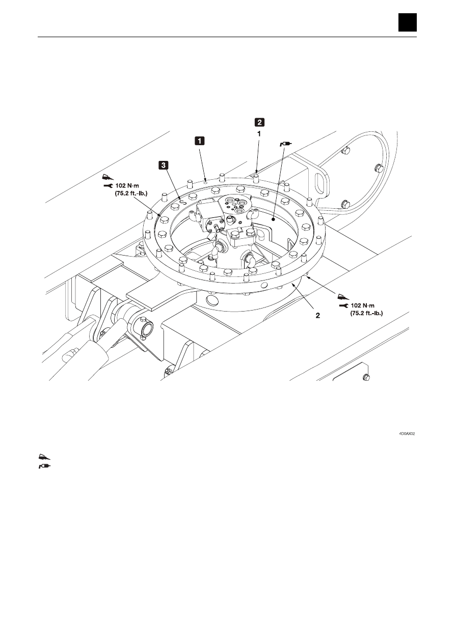
Slew bearing

Construction

ThreeBond #1324
Grease the tooth surfaces and grease bus with lithium grease EP-2.

1

Supply port hole

2

Use a reamer bolt at this position only

3

“S” die stamp 

1. Reamer bolt

2. Slew bearing

DISASSEMBLY AND ASSEMBLY

SLEW EQUIPMENT

4

4

SLEW EQUIPMENT

4D0AX00

Removing the slew bearing

1. Remove the hoe attachment.

“Removing the hoe attachment”

2. Remove the upper frame.

3. Remove the fixing bolts for the inner race.

Bolt: ThreeBond #1324
Bolt: 102 N·m (75.2 ft.-lb)

4. Raise the slew bearing (2), and remove it.

Slew bearing: 18 kg (40 lb)

Installing the slew bearing

To install, follow the same procedures as for removal but
in the reverse order.
• Refer to the construction diagram for the positions of

the reamer bolts and the grease supply port.

• Grease the tooth surfaces and grease bus with lithium

grease EP-2.

DISASSEMBLY AND ASSEMBLY

SLEW EQUIPMENT

5

4

SLEW EQUIPMENT

4D0AX00

Swivel joint

Construction

ThreeBond #1324

1. Swivel joint

2. Stopper

DISASSEMBLY AND ASSEMBLY

SLEW EQUIPMENT

6

4

SLEW EQUIPMENT

4D0AX00

Removing the swivel joint

1. Remove the upper frame.

“Removing the upper frame”

2. Disconnect the hydraulic hoses from the swivel joint

(1).

3. Take out the bolt holding the stopper in place, and

remove the stopper (2).

Bolt: ThreeBond #1324
Bolt: 102 N·m (75.2 ft.-lb)

4. Take out the bolts holding the swivel joint (1) in place,

and remove the swivel joint (1).

Bolt: ThreeBond #1324
Bolt: 26 N·m (19.2 ft.-lb)

5. Raise the swivel joint (1), and remove it.

Swivel joint: 12 kg (27 lb)

Installing the swivel joint

For installation, follow the same procedures as for remov-
al but in the reverse order.
• When installing the swivel joint, secure it in place tem-

porarily using bolts, and position the center using a
dial gauge.

• Adjust the position so that the center offset is 1 mm

(0.0394 in.) or less.

DISASSEMBLY AND ASSEMBLY

UPPER FRAME

1

4

UPPER FRAME

4E0AX00

UPPER FRAME

Upper frame

Construction

Apply molybdenum disulfide grease.
ThreeBond #1324

1. Upper frame

5. Cover

2. Counterweight

6. Cover

3. Bushing

7. Cover

4. Shim (Selected usage)

DISASSEMBLY AND ASSEMBLY

UPPER FRAME

2

4

UPPER FRAME

4E0AX00

1

To the slew motor

2

To the slew bearing

3

To the swing cylinder

4

Use the spiral tube to keep the hoses and machine body from coming
into contact with each other.

8. Grease fitting

12. Hose

9. Adapter

13. Hose

10. Elbow

14. Spiral tube

11. Hose

15. Adapter

DISASSEMBLY AND ASSEMBLY

UPPER FRAME

3

4

UPPER FRAME

4E0AX00

Removing the upper frame

1. Remove the hoe attachment.

“Removing the hoe attachment”

2. Take out the canopy.

“Removing the canopy”

3. Remove the covers.

“Removing the covers” 

4. Disconnect the hydraulic hoses from the swivel joint.

“Removing the swivel joint”

5. Take out the bolts holding the swivel joint stopper in

place, and remove the stopper.

“Removing the swivel joint”
Bolt: 102 N·m (75.2 ft.-lb) 
ThreeBond #1324

6. Disconnect the adapter (15) from the slew bearing.

7. Remove all of the fixing bolts for the outer race of the

slew bearing except for two at the front of the ma-
chine and two at the rear.

• When installing the slew bearing, be sure to align

it with the positions of the grease supply port and
the reamer bolt.

“Removing the slew bearing”
Bolt: ThreeBond #1324
Bolt: 102 N·m (75.2 ft.-lb)

8. Lift up the upper frame (1) temporarily, and remove

the remaining bolts while maintaining the upper
frame (1) in balance.

9. Lift up the upper frame, and remove it.

Installing the upper frame

To install, follow the same procedures as for removal but
in the reverse order.

DISASSEMBLY AND ASSEMBLY

UPPER FRAME

4

4

UPPER FRAME

4E0AX00

Covers

Construction

1. Engine hood

8. Bracket

2. Side cover L

9. Pin

3. Side cover R

10. Rod

4. Side frame L

11. Plate

5. Side frame R

12. Plate

6. Cover

13. Plate

7. Hinge

14. Spacer

DISASSEMBLY AND ASSEMBLY

UPPER FRAME

5

4

UPPER FRAME

4E0AX00

Removing the covers

1. Remove the engine hood (1).

a. Open the engine hood, and raise it up temporari-

ly.

b. Take out the mounting bolts in the hinge, and re-

move the pins.

Engine hood: 11 kg (26.5 lb.)

2. Take out the mounting bolts holding the side covers

L and R in place, and remove the side covers.

3. Take out the mounting bolts holding the side frames

L and R in place, and remove the side frames.

Installing the covers

To install, follow the same procedures as for removal but
in the reverse order.

DISASSEMBLY AND ASSEMBLY

UPPER FRAME

6

4

UPPER FRAME

4E0AX00

CANOPY

Construction

1. Canopy

2. Roof

DISASSEMBLY AND ASSEMBLY

UPPER FRAME

7

4

UPPER FRAME

4E0AX00

Removing the canopy

1. Remove the battery ground cable from the battery

terminal.

2. Disconnect the electrical wiring from the canopy.

3. Take out the mounting bolts.

Bolt: 135 N·m (99.6 ft-lb) 

4. Suspend the canopy and then remove it.

Canopy: 48 kg (105 lb)

DISASSEMBLY AND ASSEMBLY

OPERATING DEVICE

1

4

OPERATING DEVICE

4F0AX00

OPERATING DEVICE

Control levers

Construction

DISASSEMBLY AND ASSEMBLY

OPERATING DEVICE

2

4

OPERATING DEVICE

4F0AX00

ThreeBond #1324
Apply grease to the inside surfaces of the DU bushing during assembly.

1

Adjust the pedal so that it is not de-
pressed at a position away from the
center.

2

After putting together the machine
lever assembly, check the opera-
tion of the travel lock section and
sliding plate.

3

Adjust the lever so that it is oriented
at a right angle when set to neutral.

1. Bracket

17. Bracket

33. Lever

2. Mini pillow bearing unit

18. Lock cylinder

34. Bracket

3. Lever

19. Plate

35. Elbow

4. Lever

20. Plate

36. Elbow

5. Lever

21. Plate

37. Yoke

6. Travel lever R

22. Bracket

38. Bracket

7. Travel lever L

23. Pedal

39. Plate

8. Shaft

24. Pedal

40. Bracket

9. Mini pillow bearing unit

25. Rod end

41. Bracket

10. Shaft

26. Rod end

42. Lever

11. Lever

27. Set screw

43. Control cable

12. Lever

28. Yoke R

44. Lever

13. Lever

29. Lever

45. Rod

14. Lever

30. Yoke L

46. Bracket

15. Lever

31. Rod

16. Lever

32. Bracket

DISASSEMBLY AND ASSEMBLY

OPERATING DEVICE

3

4

OPERATING DEVICE

4F0AX00

Dozer blade lever

Construction

Apply grease to the inside surfaces of the DU bushing during assembly.

1

Lever control force: 28 N (6.31 lbf)

1. Control cable

2. Yoke

3. Lever

DISASSEMBLY AND ASSEMBLY

OPERATING DEVICE

4

4

OPERATING DEVICE

4F0AX00

Lever stand

Construction

Pilot valve (Left)

1

Adjusting the limit switch: When the limit switch is in the ON posi-
tion, the tip of the switch should be visible from the boot.
Apply rubber grease #9106 (for natural rubber).

Apply grease to the inside of the bushing during assembly.

1. Control box L

6. Lever

2. Bracket

7. Shaft

3. Plate

8. Pilot valve (Left)

4. Bracket

9. Gas spring

5. Plate

10. Limit switch

DISASSEMBLY AND ASSEMBLY

OPERATING DEVICE

5

4

OPERATING DEVICE

4F0AX00

Pilot valve (Right)

1. Control box R

2. Bracket

3. Plate

4. Pilot valve (Right)


Content      ..     5      6      7      8     ..