Takeuchi Mini Excavator TB215R (No.215000003~). Operator's Manual - page 5
 

  Index      Manuals     Takeuchi Mini Excavator TB215R (No.215000003~). Operator's Manual


Search            copyright infringement  


Content      ..     3      4      5      6     ..


Takeuchi Mini Excavator TB215R (No.215000003~). Operator's Manual - page 5


FUNCTION

SELECTOR VALVE

3

3

SELECTOR VALVE

3K8AQ00

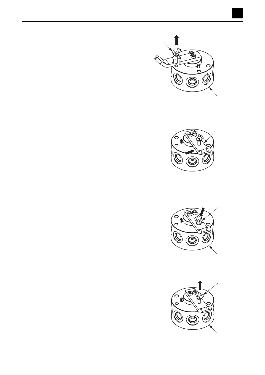
Switching from Position A (ISO) to Position G (JCB) 

1. Loosen the wing bolt (1) enough for its end to

emerge from the hole in the body (2).

2. Turn the lever (3) counterclockwise 90°.

3. Tighten the wing bolt (1) by hand.

• The end of the wing bolt (1) should go into the

anti-rotation hole in the body (2).

Switching from Position G (JCB) to Position A (ISO) 

1. Loosen the wing bolt (1) enough for its end to

emerge from the hole in the body (2). 

3K8AQ03Z

1

2

3K8AQ04Z

3

3K8AQ05Z

1

2

3K8AQ06Z

1

2

FUNCTION

SELECTOR VALVE

4

3

SELECTOR VALVE

3K8AQ00

2. Turn the lever (3) clockwise 90°.

3. Tighten the wing bolt (1) by hand. 

• The end of the wing bolt (1) should go into the

anti-rotation hole in the body (2).

3K8AQ07Z

3

3K8AQ08Z

1

2

FUNCTION

CYLINDERS

1

3

CYLINDERS

3L0AQ00

CYLINDERS

The pressure oil flowing alternately in through the outlet
and inlet on both sides (head and rod sides) of the piston
acts on the piston and its force causes the piston to move
back and forth.
For those cylinders with a cushion mechanism, the shock
resulting from the piston colliding with the cover at the
stroke end is dampened by the mechanism.

Cushion mechanism

When the piston (1) approaches the stroke end and ap-
pears likely to bump into the cover (2), the cushion bear-
ing (3) that is moving ahead of the piston enters the cush-
ion seal (4). Since this shuts off the return channel for the
hydraulic oil on the back of the piston, the oil is expelled
only from the throttle hole or the groove provided in the
cushion bearing (3). This causes the piston (1) backpres-
sure to increase, slowing the piston speed.

FUNCTION

TRAVEL MOTOR

1

3

TRAVEL MOTOR

3M0AX00

TRAVEL MOTOR

Hydraulic motor

The cylinder block (1) is formed of the pistons (2), and its
end surface comes in contact with the valve plate (3) that
contains the two half-moon-shaped ports B and C. The
cylinder block (1) rotates freely and is connected to the
drive shaft (4) via the splines. Meanwhile, the swash
plate (5) is secured to the housing.
When the high-pressure oil is directed to the port B, the
pistons (2) push against the swash plate (5) with a force
F per piston.
F = P × A,  where P: Pressure, A: Cross-sectional area of
piston
The pushing force F applied against the swash plate (5)
by the pistons (2) has two components: a force F1 com-
ponent that pushes against the swash plate and a force
F2 component that rotates the cylinder block (1). The to-
tal sum of the components in the direction of rotation of
the piston on the high-pressure side generates a rota-
tional force in the cylinder block (1), resulting in the
torque being transmitted to the shaft (4) via the splines,
causing it to turn. Conversely, if high-pressure oil is in-
stead introduced into the port C, rotation will occur in the
reverse direction of that described above.

Counterbalance valve

When the high-pressure oil is directed into the port P1,
the oil pushes the check valve (6) upward and then flows
into both the motor port M1 and the chamber B in the pilot
section. The pressure oil flows into the motor from the
motor port M1. By contrast, the return oil from the motor
does not flow into the port P2 because the passage be-
tween the motor port M2 and the port P2 is blocked by
the check valve (6), which causes the pressure in the
port P1 and chamber B to rise. When the pressure in the
chamber B rises to exceed that of the set value for the
spring (7), the spool (8) is moved to the left to connect the
motor port M2 with the port P2. This causes the motor to
start running.

If the motor speed becomes too fast and the volume of
oil flowing out of the motor port M2 becomes greater than
that flowing into the motor port M1, the pressure in the
port P1 and chamber B will drop. When the pressure in
the chamber B drops to a value lower than the set pres-
sure value of the spring (7), the spool (8) attempts to
move back to the right. As a result, the flow of the return
oil is narrowed down at the section D to generate a back
pressure in the motor port M2 and slow down the motor
speed. If the motor speed decreases, the pressure in the
port P1 and the chamber B again rises, causing the
spool (8) to move to the left. The back pressure generat-
ed in the motor port M2 is then eliminated. As thus de-
scribed, the motor is controlled to run at a speed propor-
tional to the volume of the oil flowing into it.

FUNCTION

TRAVEL MOTOR

2

3

TRAVEL MOTOR

3M0AX00

When the high-pressure oil that is directed to the port P1
is shut off, the pressure in the port P1 becomes equal to
that in the port P2 and the spool (8) attempts to return to
the neutral position using the force of the spring. This
pushes the oil in the chamber B out to the port P1 side.
At this time, the oil flow is narrowed down at the orifice
(9), resulting in the spool (8) being slowly returned to the
neutral position. In this way, the motor can thus be shut
down without being affected by shocks as they are ab-
sorbed.

2-speed mechanism

2-speed control valve

The pressure in the chamber C is low when the high-
pressure oil is directed to the motor port M1 and the trav-
el 2-speed solenoid valve (1) is at the 1st speed side po-
sition because the chamber C is connected to the tank
passage via the 2-speed solenoid valve (1). This causes
the spool (2) to be pushed to the left by the spring (4) and
the piston chamber (3) that controls the swash plate to
become connected to the tank port (T). There is no force
pushing the swash plate (5) upward at this time.

When the 2-speed travel solenoid valve (1) is switched to
the 2nd-speed position, the pressure oil from the 2-
speed travel solenoid valve (1) flows into the chamber C,
which causes the spool (2) to move to the right. Once the
spool (2) is moved to the right, the motor port M1 is con-
nected to the port A and the motor port M2 to the port B.
This causes the pressure oil from the motor port M1 to
move the shuttle spool (12) to the right and to flow into the
piston chamber (3) of the piston that controls the swash
plate. The control piston (11) then operates to push the
swash plate (5) upward.
Since there is no pressure oil supplied while the engine
is stopped, the spool (2) is then returned to the 1st-speed
position by the spring (4).

FUNCTION

TRAVEL MOTOR

3

3

TRAVEL MOTOR

3M0AX00

Swash plate

As shown in the figure, the swash plate (5) has three
planes, A, B and C, and is mounted to the flange holder
(6) such that its angle of inclination with respect to the
flange holder (6) can be changed using the two steel
balls (7).
The swash plate control piston chamber (3) is connected
to the tank port when the 2-speed control valve is
switched to the 1st-speed side. In addition, the swash
plate (5) is stabilized at surface “A” by the forces of the
piston assembly (8) and the springs (9) and (10), result-
ing in the swash plate being oriented at an angle, á,
which enables the motor to run in 1st-speed (low speed).

The swash plate control piston chamber (3) is connected
to the motor drive pressure port when the 2-speed con-
trol valve is switched to the 2nd-speed side. In addition,
the swash plate (5) is stabilized at surface “B” due to the
equilibrium between the force of the springs (9), (10) and
the force of the 2-speed control piston (11), resulting in
the swash plate being oriented at an angle, , which en-
ables the motor to run in 2nd speed (high speed).
When the engine is stopped, the pilot pressure of the 2-
speed control valve is cut off, which causes the swash
plate (5) to be stabilized at surface A at an angle of incli-
nation, á, resulting in the control valve being moved to
the 1st-speed side by the force of the springs (9) and
(10). Because of this, the motor is always set to the 1st-
speed setting when the engine is started.

Automatic 2-speed switching

When the size of the load applied to the travel motor dur-
ing travel operation in 2nd (high) speed increases, the
hydraulic pressure passing through the passage (1) from
the counterbalance and working on the valve (2) increas-
es. This causes the valve (2) to move to the left. Once the
valve (2) is moved to the left, the pressure oil that has
been flowing through the shuttle valve (12) and the valve
(2) to work on the piston (11) then flows into the tank pas-
sage. The piston (11) returns to its prior position, and the
motor is switched to 1st (low) speed.

FUNCTION

TRAVEL MOTOR

4

3

TRAVEL MOTOR

3M0AX00

Parking brake

The friction disc (2) and the disc (1) are connected via
the spline. The friction disc (2) and the disc (1) are
pressed against the flange holder (6) by the springs (4)
via the brake piston (5). The friction force between these
discs generates a braking torque that works to prevent
the cylinder block (3) from rotating.

When the pressure oil is introduced into the motor, the oil
flows from the parking brake release port (7) into the
brake piston chamber (8). The oil pressure overpowers
the spring force and moves the brake piston (5) to the
right. This generates a clearance between the friction
disc (2) and the disc (1) that works to release the parking
brake function.
Once the motor stops, no pressure oil flows into the park-
ing brake release port (7), and the parking brake force is
operated by the spring (4).

Reduction gears

The reduction gears consist of simple two-stage plane-
tary gear assemblies connected in series. Each plane-
tary gear assembly consists of a sun (input) gear, an in-
ternal ring gear with teeth that point inward, and planet
gears mounted on a carrier. The sun gear “floats” within
the planet gears so as to attain a uniform load distribution
over multiple gear mesh points.
The motor drives the 1st-stage sun gear (1), which in turn
drives the 1st-stage planet gears (2). Since these planet
gears (2) are engaged with the ring gear (3), their rota-
tion is transmitted to the 1st-stage carrier (4).
The 1st-stage carrier (4) is coupled directly to the 2nd-
stage sun gear (5), which drives the 2nd-stage planet
gears (6).
The 2nd-stage carrier (7) is a part of the motor housing
and thus non-rotating, which means that the main torque
is output to the ring gear (3). The output flange rotates in
the direction opposite that of the input rotation.

FUNCTION

SLEW MOTOR

1

3

SLEW MOTOR

3N0AX00

SLEW MOTOR

Hydraulic motor 1

The high-pressure oil that flows from the main port (1) passes through the valve (2) and valve plate (3) and into the
geroler (4). The geroler (4) is formed of a stator (5), which is installed in the housing and has seven rollers on its inner
side, and a roller (6). The inner rotor has six external teeth. These teeth divide the geroler into seven internal chambers.
The rotor (6) is designed to orbit around the inside of the stator (5).
Meanwhile, the valve (2) has twelve oil holes, six of which are provided for high-pressure oil to flow into and another
six for the return oil to flow into. The valve plate (3) also has seven oil holes, which are connected to the seven chambers
in the gerolor (4). The circuit to the gerolor (4) is then opened when the seven oil holes in the valve plate (3) are con-
nected to some of the twelve oil holes in the valve.
As thus described, the planetary motion of the rotor (6) in the gerolor (4) is initiated by the hydraulic pressure. Of the
planetary motion present in the system, only the rotating motion of the rotor itself is extracted from the drive shaft (7)
and transmitted to the shaft (8).
The rotating motion of the rotor (6) is transmitted to the valve through the valve drive shaft (9).
In this way, the oil holes in the valve (2) connected to the oil holes in the valve plate (3) are shifted in turns whenever
the valve (2) rotates. This allows the high-pressure oil that entered the gerolor (4) to flow into the different chambers in
turns. As a result, the motor is able to continuously rotate.

FUNCTION

SLEW MOTOR

2

3

SLEW MOTOR

3N0AX00

Hydraulic motor 2

Figure 1 shows that the rotor (6) rotates in the direction of the arrow while making contact with the inside of the stator
(5) when the high-pressure oil is directed into the chambers B, C and D. This in turn causes the valve (2) to rotate,
which causes the chambers into which the high-pressure oil is directed to be successively shifted in the direction op-
posite the direction of the arrow. Figure 2 shows that the rotor (6) has turned 1/14 of a revolution, resulting in the cham-
bers into which the high-pressure is to be directed to be shifted to the chambers A, G and F. At this time, the center
point Y of the rotor (6) is shifted to the point Y’ around the point X. This point Y’ is further shifted to Y” as shown in Figure
3. In other words, the center of the rotor (6) rotates 6/7 of a revolution around the point X, changing its position from Y
to Y’ and then to Y”. Figure 4 shows that the center of the rotor is returned to point Y from point Y’’ to complete one cycle
of the shifting of the chambers into which the high-pressure oil is to be directed.
At this time, the “•” mark on the rotor (6) rotates 1/6 of a revolution in the direction opposite that of the motion of point Y.
As a result, the output shaft is made to rotate one complete rotation by the high-pressure oil, which is directed into 42
chambers, which is 7 chambers × 6 cycles = 42 chambers.

FUNCTION

SLEW MOTOR

3

3

SLEW MOTOR

3N0AX00

Brake valve

This valve is equipped with a shockless function.
When the high-pressure oil enters the port Av, it flows
through the orifice (1) and into the damper chamber (2)
where it attempts to move the plunger (3) to the right. At
this time, the spring (4) remains in its set position.
When the pressure in the pressure oil increases to where
it overpowers the spring force of the spring (4), the
plunger (3) is moved to the right. This causes the pres-
sure in the pressure oil to be released into the Bv port
through a relief operation.
At the same time, the pressure oil flows through the ori-
fice (6) and enters the piston chamber (B), where it works
in the direction of spring compression to compress the
spring (4). At this time, the spring force increases in pro-
portion to the distance traveled by the piston (5), which
causes the relief pressure to increase.
The spring (4) is compressed the most when the piston
(5) is moved left to the stroke end. At this time, the pres-
sure becomes the set relief pressure.

Parking brake

The friction discs (1) are each connected to the pinion
gear (2) via the spline, and the center discs (3) are also
each connected to the bearing housing (4) via the spline.
The friction discs (1) and the center discs (3) are each
pressed against the bearing housing (4) by the springs
(5) via the brake piston (6). The friction force between
these discs generates a braking torque that prevents the
pinion gear (3) from rotating.
When the oil is directed from the parking brake release
port to the piston chamber (A), the oil pressure overpow-
ers the spring force and acts to move the brake piston
(6). This creates a clearance between the friction discs
(1) and the center discs (3), which works to release the
parking brake function.

FUNCTION

SWIVEL JOINT

1

3

SWIVEL JOINT

3O0AX00

SWIVEL JOINT

The swivel joint is located at the slew center of the ma-
chine and has the role of continuing to connect the oil cir-
cuit regardless of the slew angle of the upper frame. 
A number of ports (3) equal to the number of fluid circuits
is provided on a hub (1) and shaft (2) that are mutually
rotatable. Grooves used as oil channels are processed
into the inner periphery of the hub (1) and the outer pe-
riphery of the shaft (2). A seal (4) is applied to the top and
bottom of the peripheral grooves. The oil flowing from the
port (3) continues to flow through the oil pressure chan-
nel (5) between the hub (1) and shaft (2) to enable con-
tinued connection of the circuit located between the slew
assemblies without being blocked due to rotation.

Selector

The swivel joint is equipped with a selector valve that can
be used to switch between separate circuits. The selec-
tor valves switches between the blade cylinder and the
spanner cylinder.

When the spool (2) of the selector (1) is set to the left, port
P of the selector (1) is connected to port E of the swivel
joint (3). This allows the oil from the control valve to flow
into the dozer blade cylinder.

When the spool (2) of the selector (1) is moved to the
right, port P of the selector (1) is connected to port G of
the swivel joint (3). This allows the oil from the control
valve to flow into the spanner cylinder.

C4D703

P

1

2

3

E

G

C4D704

P

2

E

G

DISASSEMBLY AND ASSEMBLY

4

DISASSEMBLY AND ASSEMBLY

SERVICE STANDARDS

1

4

SERVICE STANDARDS

4A0AX00

SERVICE STANDARDS

Track roller

Shoe slider

Sprocket

Idler

Code

Criteria, mm (in.)

Standard dimension

Allowable value

A

75 (3.0)

69 (2.7)

B

25 (1.0)

Code

Criteria, mm (in.)

Standard dimension

Allowable value

A

9 (0.4)

4.5 (0.2)

Code

Criteria, mm (in.)

Standard dimension

Allowable value

A

251.6 (9.9)

241.6 (9.5)

B

24 (0.9)

Code

Criteria, mm (in.)

Standard dimension

Allowable value

A

232 (9.1)

226 (8.9)

B

30 (1.2)

4A0AF03Z 

B

A

DISASSEMBLY AND ASSEMBLY

SERVICE STANDARDS

2

4

SERVICE STANDARDS

4A0AX00

Clearance for pin and bushing

DISASSEMBLY AND ASSEMBLY

SERVICE STANDARDS

3

4

SERVICE STANDARDS

4A0AX00

Replacing the pin and bushing

Replace the pin or the bushing if there is looseness of 1 mm (0.04 in.) or more.

Unit: mm (in.)

Code

Item

Standard dimension

1

Bucket and arm

30 (1.18)

2

Bucket and link

30 (1.18)

3

Arm and link

30 (1.18)

4

Bucket cylinder and link

30 (1.18)

5

Bucket cylinder and arm

30 (1.18)

6

Arm and boom

35 (1.38)

7

Arm cylinder and arm

35 (1.38)

8

Arm cylinder and boom

35 (1.38)

9

Boom and swing bracket

35 (1.38)

10

Boom cylinder and boom

35 (1.38)

11

Boom cylinder and swing bracket

35 (1.38)

12

Swing bracket and turntable

50 (1.97)

13

Swing bracket and turntable

50 (1.97)

14

Swing cylinder and swing bracket

30 (1.18)

15

Swing cylinder and turntable

30 (1.18)

16

Blade cylinder and blade

30 (1.18)

17

Blade cylinder and lower frame

30 (1.18)

18

Blade and lower frame

30 (1.18)

19

Spanner cylinder and frame R

30 (1.18)

20

Spanner cylinder and frame L

30 (1.18)

DISASSEMBLY AND ASSEMBLY

DRIVE SYSTEM

1

4

DRIVE SYSTEM

4B0AX00

DRIVE SYSTEM

Engine

25.4 N·m (18.8 ft.-lb) or below

1

Use a shim to adjust the clearance between the en-
gine hood and stopper.

• Clearance “a”: 5 mm (0.2 in.)
• Clearance “b”: 6 mm (0.24 in.)

1. Radiator assembly

8. Drain valve

2. Fan guard

9. Tank

3. Air cleaner assembly

10. Cushion rubber

4. Hose

11. Earth ground cable

5. Hose

12. Cushion rubber

6. Stopper

13. Shim

7. Indicator

14. Shim


Content      ..     3      4      5      6     ..