Takeuchi Mini Excavator TB215R (No.215000003~). Operator's Manual - page 4
 

  Index      Manuals     Takeuchi Mini Excavator TB215R (No.215000003~). Operator's Manual


Search            copyright infringement  


Content      ..     2      3      4      5     ..


Takeuchi Mini Excavator TB215R (No.215000003~). Operator's Manual - page 4


FUNCTION

GEAR PUMP

1

3

GEAR PUMP

3I1AV00

GEAR PUMP

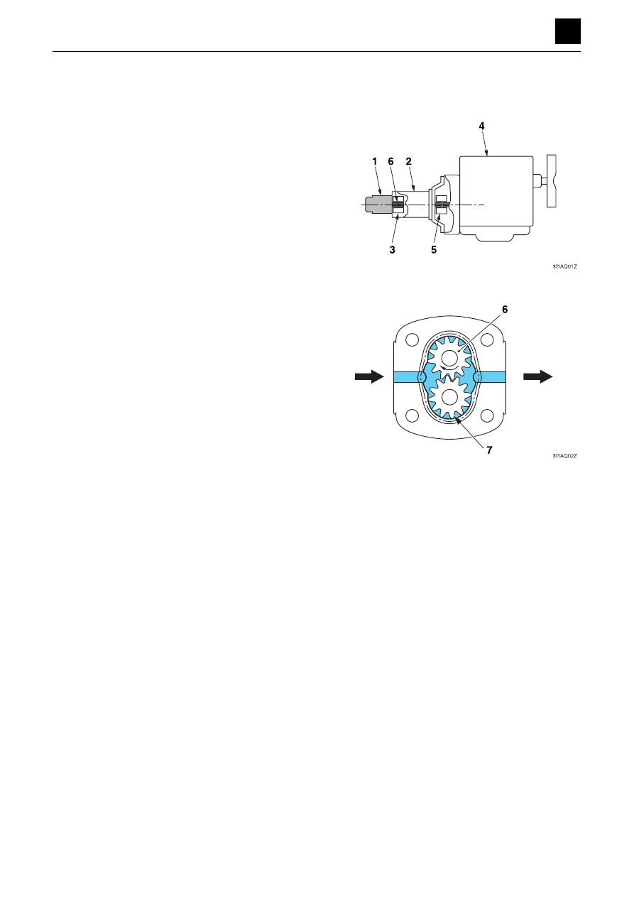
The gear pump (1) is a constant-volume pump with dou-
ble-gear pumps (P3, P4) that discharges a constant vol-
ume of discharge material over a constant speed. 
The pump P3 is used for the 2nd and 3rd auxiliary line
piping, blade, and slew motor, and the pump P4 is used
to discharge the pilot pressure oil.
The gear pump (1) is connected by the hydraulic pump
(piston) (2) and coupling (3), and the hydraulic pump (2)
is connected by the engine (4) and coupling (5), with the
drive gear (6) of the gear pump (1) being rotated with the
rotation of the engine. 

The gear pump is located inside one of the gear cases
and is interlocked with the drive gear (6) and driven gear
(7). When the drive gear (6) is rotated, the space be-
tween the case and the gears is filled with that oil flowing
from the inlet to the outlet.

FUNCTION

CONTROL VALVE

1

3

CONTROL VALVE

3J0AX00

CONTROL VALVE

When the spools are in the neutral position:

When the control valve spools are not moved, the oil
flows through the center bypass passage (1) and the
tank passage T to return to the tank, as shown by the ar-
row.

When the spool is being operated:

The description given here uses an example in which the
spool (2) is moved to the right.
When the spool (2) is moved to the right, the center by-
pass passage (1) is closed and the oil that has flowed
into the valve from the pump passes through the parallel
passage (4), the load check valve (5), and port A into the
actuator.
Meanwhile, oil returning from port B returns to the tank
through the tank passage T.

Load check valve

This valve prevents oil from flowing backward while the
spool switching operation is being performed due to the
load pressure C coming from the actuator port.

FUNCTION

CONTROL VALVE

2

3

CONTROL VALVE

3J0AX00

Main relief valves

A main relief valve is mounted between the pump circuit
and tank circuit of each inlet housing and works to main-
tain the circuit pressure at the set value.

The relief valve remains turned off:

As long as the pressure in the circuit is lower than the set
pressure, the relief valve will maintain the pressure equi-
librium and remain shut off. The hydraulic pressure from
the pump passes from the chamber C into the orifice of
the main poppet (2) and then on until it reaches the
chamber D and needle valve (1). Meanwhile, the forces
F and F1 act on the sides of the main poppet (2), as indi-
cated by the arrows.
F = P × A
F1 = P × A1  (P: Pressure, A and A1: Cross-sectional ar-
eas)
The cross-sectional area A1 is larger than the cross-sec-
tional area A, which causes the main poppet (2) to be
pushed to the left seat surface by the force of F1 - F.

The relief valve is activated:

If the pressure in the circuit becomes higher than the set
pressure of the spring (3), the needle valve (1) will be
pushed to the right by hydraulic pressure, which will
cause the oil to flow into the tank passage T. When this
happens, a pressure differential is generated between
the two ends of the orifice of the main poppet (2), which
causes the main poppet to be pushed to the right by the
hydraulic pressure. As a result, the pressure oil in the cir-
cuit flows into the tank passage as shown by the arrows.
This operation works to maintain the pressure in the cir-
cuit at the set value.

FUNCTION

CONTROL VALVE

3

3

CONTROL VALVE

3J0AX00

Port relief valve

The port relief valve is located between the actuator and
the tank circuit T. It protects the actuator from pressure
shocks caused by the sudden blocking of the actuator
port or by overloading, or absorbs abnormal pressure
generated by an external force.

The relief valve is subjected to the relief operation:

As long as the pressure in the circuit is lower than the set
pressure, the relief valve will maintain the pressure equi-
librium and remain shut off. The hydraulic pressure from
the pump passes from the chamber B through the orifice
of the piston (4) and on until it reaches the chamber C
and the needle valve (5).
Meanwhile, the forces F and F1 act on the sides of the
main poppet (6) as indicated by the arrows.
F = P × A
F1 = P × A1  (P: Pressure, A and A1: Cross-sectional ar-
eas)
The cross-sectional area A1 is larger than the cross-sec-
tional area A, which causes the main poppet (2) to be
pushed to the left seat surface by the force of F1 - F.

If the pressure in the circuit becomes higher than the
force of the spring (7), the needle valve (5) is pushed to
the right by hydraulic pressure, connecting the high-
pressure area with the tank passage T. The oil then flows
around the circumference of the needle valve (5) and
passes through the slits, flowing into the tank passage T.

When the needle valve (5) is pushed to the right, which
connects the high-pressure area with the tank passage
T, the pressure behind the piston (4) drops; consequent-
ly, the piston (4) is pushed to the right and up against the
needle valve (5). As a result, the flow of oil from chamber
B to chamber C is cut-off, and the pressure in chamber
C drops.

FUNCTION

CONTROL VALVE

4

3

CONTROL VALVE

3J0AX00

The pressure in chamber C drops below that in chamber
B, causing the pressure to become unequal. This causes
the main poppet (6) to open up, which allows the pres-
sure oil to flow to the tank passage T.

When the valve is engaged in valve suction opera-
tion:

If the cylinder is operated at a speed too fast for the oil
supply to keep up, and thus the pressure of the chamber
B becomes almost negative, oil is supplied from the tank
to prevent cavitation.
When the pressure in chamber B is lower than the pres-
sure in the tank passage T, the difference in cross-sec-
tional areas between A and A1 causes the main poppet
(6) to open. This, in turn, causes oil to enter from the tank
passage T to fill in the empty space in the chamber B.

FUNCTION

CONTROL VALVE

5

3

CONTROL VALVE

3J0AX00

Anti-cavitation valve

This valve is inserted between the cylinder port and the
tank passage. It works to supply oil from the tank to pre-
vent cavitation when the cylinder is operated at a speed
that is too fast for the oil supply to keep up, which would
cause the pressure of the cylinder port to become almost
negative.

Under normal conditions, a pressure is applied to the cyl-
inder port (P), which causes the poppet (1) to remain
closed. A negative pressure arises in the cylinder port
(P). When the pressure drops below that in the tank pas-
sage (T), the poppet (1) is pushed open, allowing oil to
flow from the tank passage (T) and into the cylinder port
(P).

Anti-drift valve

This valve is installed in the head side of the cylinder cir-
cuit of the boom section. It is designed to prevent oil from
leaking into the cylinder head circuit when the spools are
in the neutral position and to decrease the natural drop
of the boom.

FUNCTION

CONTROL VALVE

6

3

CONTROL VALVE

3J0AX00

Switch valve

This valve switches among the circuits of the bucket,
arm, boom, swing, and auxiliary line hydraulics when any
of them is activated during travel operation. The oil sup-
plied by the pump P3 is directed to a section other than
the travel section, which enables straight travel together
with other operations under combined control.

When the switch valve is activated:

When travel operation and other operations are per-
formed at the same time, the pilot pressure is directed to
the port P1, which causes the spool (1) to be pushed up.
This allows the oil that entered the port P to flow through
the parallel passage (2) as well as the spool head and
the second parallel passages A and B. The second par-
allel passage A is connected to the boom and bucket
sections while the second parallel passage B is connect-
ed to the arm and swing sections, allowing combined op-
eration involving travel and other operation.

When the switch valve is not activated:

The spool (1) does not get switched because the pilot
passage is open to the tank passage and thus the pres-
sure in the port Pi is equal to the pressure in the tank. As
a result, the oil that entered the port P flows into the cen-
ter bypass passage (3). In addition, part of the oil flows
through the connected parallel passage (2) and the doz-
er blade and slew sections.

FUNCTION

CONTROL VALVE

7

3

CONTROL VALVE

3J0AX00

Arm In regeneration

The speed at which the arm cylinder is extended (Arm In
operation speed) can be increased by directing part of
the oil returned from the arm cylinder to the supply side
again to increase the supply flow.

When the Arm In operation is performed, the pilot pres-
sure is directed to the port PiA, which causes the spool
(1) to be pushed up. This results in the oil from the pump
being supplied to the head side of the arm cylinder
through the port A.
Meanwhile, the return oil from the rod side of the arm cyl-
inder flows from the port B through the spool head and
the tank passage to be returned to the tank. At the same
time, it pushes the regenerative poppet (2) downward,
allowing it to be joined with the flow from the pump. This
combined flow is then supplied back to the head side of
the arm cylinder again via the port A.

FUNCTION

PILOT VALVE (CONTROL LEVER)

1

3

PILOT VALVE (CONTROL LEVER)

3K2AQ00

PILOT VALVE (CONTROL LEVER)

The pilot valve is a remote-controlled valve with a reducing
valve system used to operate the spool in the control valve.
The pilot valve comes with right and left control levers.
The pilot valve casing (1) contains a vertical shaft hole
that incorporates a reducing valve (2). When the lever (3)
is tilted, the push rod (4) and spring seat (5) are pushed
down, which changes the pressure of the secondary
pressure spring (6).
The casing (1) contains the oil inlet port P (primary pres-
sure) and the tank port T. The secondary pressure which
corresponds to changes in operating angle produced
using the lever (3) can be provided through the output
ports A and B located below the vertical shaft hole. The
secondary pressure functions as the pilot pressure to ac-
tivate the spool of the control valve.

When the lever (3) is in the neutral position:

The force of the spring (6) that determines the output
pressure (secondary pressure) of the pilot valve is not
conveyed to the spool (7). This causes the spool (7) to be
pushed up by the return spring (8) and spring sheet (5),
and the output ports A and B are connected to the tank
port T, which makes the pressures in the ports A and B
be equal to the pressure in the tank port T.

When the lever (3) is tilted:

When the lever (3) is tilted and the push rod (4) is
pushed, the spring sheet (5) and spool (7) move down-
ward, and the input port P is connected to the output port
A. The oil from the pilot pump then flows into the output
port A to generate a pressure.

3K2AQ01Z

3

2

P

A

B

2

1

4

5

6

T

3K2AQ02Z

3

A

B

7

P

5
6
8

T

3K2AQ03Z

3

A

B

7

P

4

5

FUNCTION

PILOT VALVE (CONTROL LEVER)

2

3

PILOT VALVE (CONTROL LEVER)

3K2AQ00

When the lever (3) is kept at a certain position:

When the pressure in the output port A increases to a lev-
el equivalent to the force of the spring (6) set by the incli-
nation of the lever (3), the hydraulic pressure is balanced
with the spring force. When the pressure in the output
port A becomes higher than the set spring force, the out-
put port A is disconnected from the input port P and then
becomes connected to the tank port T. When the pres-
sure in the output port A drops below than the set spring
force, the output port A becomes connected to the input
port P and it is then disconnected from the tank port T.
The secondary pressure is thus always kept constant.

3K2AQ04Z

3

A

B

6

P

FUNCTION

PROPORTIONAL CONTROL SOLENOID VALVE 

(2ND AUXILIARY LINE PIPING)

1

3

PROPORTIONAL CONTROL SOLENOID VALVE

(2ND AUXILIARY LINE PIPING)

3K4AX00

PROPORTIONAL CONTROL SOLENOID VALVE

(2ND AUXILIARY LINE PIPING)

The proportional lever (2) and proportional amplifier (3)
of the pilot valve (1) control the driving current that flows
to the proportional control solenoid valve (4), which con-
trols the pilot pressure of the control valve (5) (auxiliary
section) whereby the flow rate of the auxiliary line piping
changes.
The proportional control solenoid valve controls the sec-
ondary pressure using the built-in proportional pressure-
educing valve. The secondary pressure generated cor-
responds to the changes in current because of the force
used to generate the secondary pressure being applied
to the solenoid in accordance with the amount of current
flowing through the coil.
When current flows through the solenoid, a thrust force
proportional to the current is generated and moves the
spool (6) so that the oil supplied from the port P is intro-
duced into the port A on the secondary pressure side,
which increases the pressure Pa of the port A.
The pressure Pa acts on the differential area S between
the cross section A1 and cross section B1 of the spool
(6), and the spool (6) is pushed to the solenoid side by
the oil pressure, Pa × s. The spool (6) stops at the posi-
tion where the sum of the oil pressure, Pa × s, and the
force, Fk, exerted by the springs (7) is balanced with the
thrust force, Fs, generated by the solenoid. The weight,
Fks, of the spring (8) used for fine adjustment of the sec-
ondary pressure acts in the direction (left) of assistance
of the thrust force from the solenoid.

When  the  thrust  force  is  greater  than  a  set  value,  the
spool (6) is moved to the left, which connects the port P
(supply side) and the port A (secondary side) together
through the notch (9).

When the thrust force is lower than a set value, the spool
(6) is moved to the right, which connects the port A (sec-
ondary side) and the port T (tank side) together through
the notch (10).
The opening areas of the notch (9) on the supply side
and the notch (10) on the discharge side are thus con-
trolled by the movement of the spool (6), and a second-
ary (pilot) pressure can be provided that corresponds to
the thrust force generated by the solenoid. 

3K4AQ01Z

2

3

1

4

5

6

7

8

S=A1-B1

S

Paxs

Paxs

Fk

Fs

Fks

B1 A1

A

P

T

Fs

Fks

Fk

3K4AQ02Z

A

T

P

6

9

3K4AQ03Z

3K4AQ04Z

A

T

P

6

10

FUNCTION

SOLENOID 

VALVE

(3RD AUXILIARY LINE PIPING)

1

3

SOLENOID VALVE(3RD AUXILIARY LINE PIPING)

3K6AV00

SOLENOID VALVE(3RD AUXILIARY LINE PIPING)

This  valve  switches  circuit  connections  by  moving  the
spool using magnets and supplies the pilot pressure to
the 3rd auxiliary section.

Solenoid valve

When the solenoid is not energized:

The oil in the port P (pump side) is blocked by the spool
(1).
The oil flows through the port A (on the pilot circuit side
of the 3rd auxiliary section) and port T
(on the tank side), which means that the pressure of the
downstream  pilot  circuit  is  the  same  as  the  tank  pres-
sure.

When the solenoid is energized:

A magnetic field is generated around the coil that causes
the push rod to be pulled downward and the spool (1) to
be pushed down. This causes the oil in the port P to flow
to the port A, and the pressure is transmitted to the lower
pilot circuit.

FUNCTION

SOLENOID VALVE (LEVER LOCK)

1

3

SOLENOID VALVE (LEVER LOCK)

3K6AX00

SOLENOID VALVE (LEVER LOCK)

This valve switches circuit connections by moving the
spool using magnets and supplies the pilot pressure to
the pilot valve and 2nd-speed travel switch.
The pilot pressure is kept constant with the relief valve.

Solenoid switching and relief function

For simplification purposes, only port A will be used in
the descriptions below as port A and port B in the valve
operate in the same way.

When the solenoid is not energized:

The pressure oil from port P is blocked from entering the
circuit to port A by the spool (5) and plunger (10).
The oil flows through the port A (on the pilot circuit side
of the pilot valve or 2nd-speed travel switch) and port T
(on the tank side), which means that the pressure of the
downstream pilot circuit is the same as the tank pres-
sure.
In addition, the pressure in port C is the same as that in
port P under normal conditions as port C is connected to
port P.

When the pressure of port P increases and exceeds the
set value for the spring (11), the plunger (10) is pushed
upward, and the oil from port P flows into port T from the
“a” section.
When the pressure of the port P drops and falls below a
set value for the spring (11), the plunger (10) is moved
down by the spring (11), which blocks the circuit to the
port P and port T.
This enables the pressure inside the circuit to be main-
tained at a constant level.

When the solenoid is energized:

A magnetic field is generated around the coil that causes
the push rod to be pulled downward and the spool (5) to
be pushed down. This causes the oil in the port P to flow
to the port A, and the pressure is transmitted to the lower
pilot circuit.
When the power to the coil is turned OFF, the spool (5) is
pushed upward by the spring (4).

FUNCTION

SOLENOID VALVE (LEVER LOCK)

2

3

SOLENOID VALVE (LEVER LOCK)

3K6AX00

Check function

Port P 

J

 Port PAC and Port B

When the pressure in port P exceeds the force applied
by the spring (2), the plunger (1) moves to the right, al-
lowing the pressure oil to flow from port P to port PAC.

Port PAC 

J

 Port P

The plunger (1) is returned to the left by the spring (2),
and the port PAC and port P are blocked off to prevent
backflow into either port.

FUNCTION

SELECTOR VALVE

1

3

SELECTOR VALVE

3K8AQ00

SELECTOR VALVE

The selector valve is connected between the control
valve and the pilot valve (control lever).
Turn the selector valve lever to switch the connection
port to switch the control lever pattern.

1. Position A (ISO)

2. Position G (JCB)

3. Rotation of 90°

4. Circuit schematic

3K8AQ00Z

1

2

2

3

4

1

FUNCTION

SELECTOR VALVE

2

3

SELECTOR VALVE

3K8AQ00

Position A (ISO)

Port A 

 Port 1

Port B 

 Port 2

Port C 

 Port 3

Port D 

 Port 4

Position G (JCB)

Port A 

 Port 3

Port B 

 Port 4

Port C 

 Port 1

Port D 

 Port 2

1. Position A (ISO)

2. Position G (JCB)

3. Rotation of 90°

1. Position A (ISO)

2. Position G (JCB)

3. Rotation of 90°

3K8AQ01Z

1

2

3

3K8AQ02Z

1

2

3


Content      ..     2      3      4      5     ..