Takeuchi Mini Excavator TB215R (No.215000003~). Operator's Manual - page 3
 

  Index      Manuals     Takeuchi Mini Excavator TB215R (No.215000003~). Operator's Manual


Search            copyright infringement  


Content      ..     1      2      3      4      ..


Takeuchi Mini Excavator TB215R (No.215000003~). Operator's Manual - page 3


SERVICE DATA

PERFORMANCE CRITERIA

8

2

PERFORMANCE CRITERIA

2D0AX002

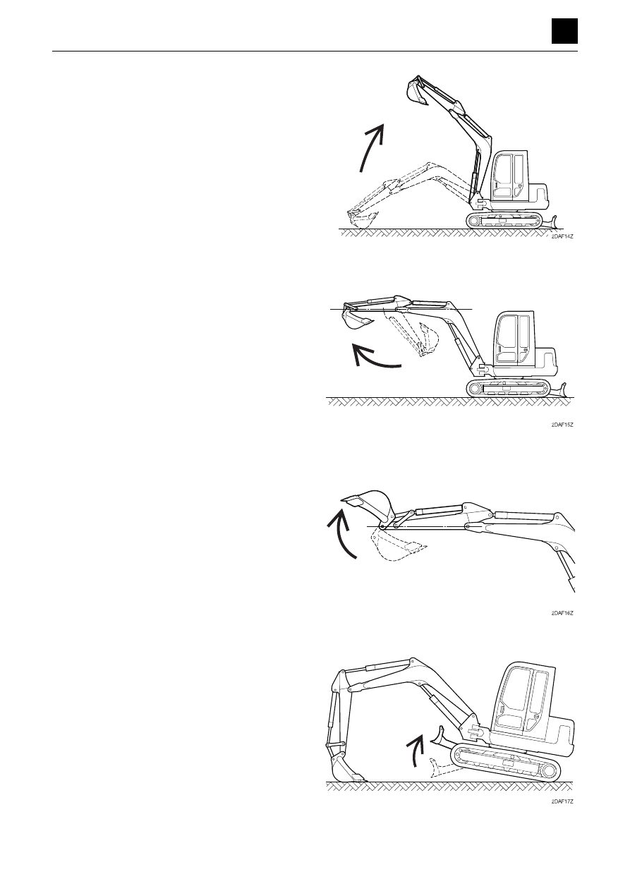
Boom cylinder speed

• Engine:

Maximum R.P.M.

• Hydraulic oil temp.: 50°C to 60°C (122°F to 140°F)
• Measuring attitude: Completely  retract  the  arm  cylin-

der, and fully extend the bucket cylinder.

• Next, measure the time required for the bucket to

reach its highest elevation point (lowest point) from its
lowest point (highest point) at rest on the ground. (ex-
clusive of cushion operating time).

Arm cylinder speed

• Engine:

Maximum R.P.M.

• Hydraulic oil temp.: 50°C to 60°C (122°F to 140°F)
• Measuring attitude: With the bucket in a no-load state,

completely retract the arm cylinder, fully extend the
bucket cylinder, position the arm horizontally, and rest
the dozer blade on the ground.

• Measure the time required for the arm cylinder to move

from the fully retracted position to the fully extended
position, and vice versa.

Bucket cylinder speed

• Engine:

Maximum R.P.M.

• Hydraulic oil temp.: 50°C to 60°C (122°F to 140°F)
• Measuring attitude: With the bucket in a no-load state,

completely retract the arm cylinder, position the arm
horizontally, and rest the dozer blade on the ground.

• Measure the time required for the bucket cylinder to

move from the fully retracted position to the fully ex-
tended position, and vice versa.

Dozer blade cylinder speed

• Engine:

Maximum R.P.M.

• Hydraulic oil temp.: 50°C to 60°C (122°F to 140°F)
• Measuring attitude: Using  the  hoe  attachment,  lift  up

the dozer blade end of the excavator.

• After raising and lowering the dozer blade one full

stroke each, measure the time required per stroke in
each direction.

SERVICE DATA

PERFORMANCE CRITERIA

9

2

PERFORMANCE CRITERIA

2D0AX002

Swing cylinder speed

• Engine:

Maximum R.P.M.

• Hydraulic oil temp.: 50°C to 60°C (122°F to 140°F)
• Measuring attitude: Same as that for measuring slew

time

• While swinging the boom from left (right) to right (left),

measure the time required for a full stroke in each di-
rection. (exclusive of cushion operating time).

Natural cylinder drop

Boom, arm bucket, dozer blade, bucket tip

• Engine:

Stopped

• Hydraulic oil temp.: 50°C to 60°C (122°F to 140°F)
• Measuring attitude: With the bucket in a no-load state,

completely retract the dozer blade and arm cylinders,
and then fully extend the bucket cylinder and make
adjustments so that the boom foot pin and bucket pin
are at the same height.

• Maintain this attitude for 5 minutes and then measure

the change in rod length and the distance that the
bucket tip moved.

Swing

• Engine:

Stopped

• Hydraulic oil temp.: 50°C to 60°C (122°F to 140°F)
• Inclination angle:

15°

• Measuring attitude: Same as that for measuring slew

time

• Rotate the upper structure so that it is directly abeam

of the grade, and then measure the change in rod
length after 5 minutes has passed.

Spanner cylinder speed

• Engine:

Maximum R.P.M.

• Hydraulic oil temp.: 50°C to 60°C (122°F to 140°F)
• Measuring attitude: Excavator body to be raised using

both the hoe attachment and the dozer blade.

• Measure the time required for the spanner cylinder to

move from the fully retracted position to the fully ex-
tended position, and vice versa.

SERVICE DATA

PERFORMANCE CRITERIA

10

2

PERFORMANCE CRITERIA

2D0AX002

Lever operating force

• With the engine turned off, place a push-pull scale on

the handle grip center or the pedal edge to measure
the force. Record the readings at the point at which the
lever/pedal reaches a full stroke.

Lever play

• Measure any discernible play at the tip of the lever or

pedal.

Backlash

• Measuring attitude: Completely retract the arm cylin-

der, and fully extend the bucket cylinder.

• Move the tips of the bucket teeth from side to side (left

and right), and measure the amount of play.

Slew bearing play

1. With the bucket in a no-load state, completely retract

the arm cylinder, fully extend the bucket cylinder,
move the dozer blade back, and make adjustments
so that the boom foot pin and bucket pin are at the
same height.

2. Attach a dial gauge to the bottom face of the slew

bearing’s outer race located near the front of the ex-
cavator, and set the dial gauge to 0.

3. Lower the boom, raise the crawler to the height, H,

and then read the dial gauge to get the measure-
ment.

SERVICE DATA

PERFORMANCE CRITERIA

11

2

PERFORMANCE CRITERIA

2D0AX002

Track tension

• Measuring attitude: Excavator body to be raised using

both the hoe attachment and the dozer blade. For
models with rubber crawlers, line up the crawler seam
joint (marked with an M or 

 symbol) with the upper

center of the upper structure.

• Measure the width of the gap between the bottom sur-

face of the frame and the top surface of the track shoe
at the center of the crawler frame.

SERVICE DATA

TIGHTENING TORQUE

1

2

TIGHTENING TORQUE

2E0BO002

TIGHTENING TORQUE

Hydraulic hose

Bite-type pipe fitting for steel pipe

Nominal thread 

diameter

Tightening torque

Parallel internal-thread 

external-seat union 

joint for piping

Tapered external-

thread joint for piping

N·m

ft-lb

N·m

ft-lb

G(R)1/8

+4.9

15

0

+3.6

11 

0

11.8 ± 1.2

8.7 ± 0.8

G(R)1/4

+4.9

25

0

+3.6

18 

0

29.4 ± 2.9

21.7 ± 2.1

G(R)3/8

+4.9

49

0

+3.6

36 

0

53.9 ± 5.4

39.8 ± 3.9

G(R)1/2

+4.9

64 

0

+3.6

47 

0

88.3 ± 8.8

65.1 ± 6.4

G(R)3/4

+4.9

132 

0

+3.6

97 

0

147.1 ± 14.7 108.5 ± 10.7

G(R)1

+4.9

196 

0

+3.6

145 

0

196.1 ± 19.6 144.7 ± 14.3

G(R)1 1/4

+4.9

225 

0

+3.6

166 

0

G(R)1 1/2

+4.9

255 

0

+3.6

188 

0

Nominal thread diameter

Tightening torque

UNF internal-thread flat-face sealing 

union joint

N·m

ft-lb

9/16-18 UNF

+4.9

25 

0

+3.6

18 

0

11/16-16 UN

+4.9

37 

0

+3.6

27 

0

13/16-16 UN

+4.9

75 

0

+3.6

55 

0

1-14 UNS

+4.9

110 

0

+3.6

81 

0

1 3/16-12 UN

+4.9

150 

0

+3.6

110 

0

1 7/16-12 UN

+4.9

190 

0

+3.6

140 

0

Outer diameter of pipe 

(mm)

Tightening torque

N·m

ft-lb

8

34.3 ± 4.9

23.5 ± 3.5

10

41.7 ± 2.5

30.7 ± 1.7

12

58.8 ± 4.9

43.4 ± 3.5

15

88.3 ± 4.9

65.1 ± 3.5

16

93.2 ± 4.9

68.7 ± 3.5

18

132.4 ± 4.9

97.6 ± 3.5

22

205.9 ± 9.8

151.8 ± 7.2

27.2

245.2 ± 9.8

181.0 ± 7.2

28

313.8 ± 19.6

231.4 ± 14.3

32

313.8 ± 19.6

231.4 ± 14.3

35

411.9 ± 19.6

303.7 ± 14.3

1

2

2E0BO04

1

Parallel internal-thread external-seat 
union joint for piping

2

Tapered external-thread joint for piping

2E0BO03

3

3

UNF internal-thread flat-face sealing 
union joint

2EAA02Z 

SERVICE DATA

TIGHTENING TORQUE

2

2

TIGHTENING TORQUE

2E0BO002

Joint for piping

Joint for piping (O-ring seal type)

Bring a magnet close to the port to check the port material.
If the port is made of steel, the magnet sticks to the port. If the
port is made of aluminum, the magnet does not stick to the port.

Nominal thread 

diameter

Tightening torque

Port material: Steel

Port material: Cast steel

N·m

ft-lb

N·m

ft-lb

R1/8

11.8 ± 1.2

8.7 ± 0.8

10.8 ± 1.1

8.0 ± 0.7

R1/4

29.4 ± 2.9

21.7 ± 2.1

24.5 ± 2.5

18.1 ± 1.7

R3/8

53.9 ± 5.4

39.8 ± 3.9

49.0 ± 4.9

36.2 ± 3.5

R1/2

88.3 ± 8.8

65.1 ± 6.4

73.5 ± 7.4

54.3 ± 5.3

R3/4

147.1 ± 14.7 108.5 ± 10.7 127.5 ± 12.7 94.1 ± 9.3

R1

196.1 ± 19.2 144.7 ± 14.3 171.6 ± 17.2 126.6 ± 12.5

Nominal thread 

diameter

Tightening torque

Port material: Steel

Port material: Aluminum

N·m

ft-lb

N·m

ft-lb

G1/8

19.6 ± 2.0

14.5 ± 1.5

19.6 ± 2.0 14.5 ± 1.45

G1/4

34.3 ± 4.9

25.3 ± 3.6

26.5 ± 4.9

19.6 ± 3.6

G3/8

53.9 ± 4.9

39.8 ± 3.6

41.6 ± 4.9

30.7 ± 3.6

G1/2

64 ± 4.9

47 ± 3.6

64 ± 4.9

47.0 ± 3.6

G3/4

132 ± 4.9

97 ± 3.6

88.2 ± 4.9

65.0 ± 3.6

G1

196 ± 9.8

145 ± 7.2

107.9 ± 9.8 79.6 ± 7.2

G1-1/4

225 ± 9.8

166± 7.2

117.7 ± 9.8 86.8 ± 7.2

G1-1/2

255 ± 9.8

188 ± 7.2

137.3 ± 9.8 101.2 ± 7.2

Nominal thread diameter

Tightening torque

N·m

ft-lb

7/16-20 UNF

16.7 ± 2.0

12.3 ± 1.4

1/2-20 UNF

22.6 ± 2.0

16.6 ± 1.4

9/16-18 UNF

31.4 ± 2.9

23.1 ± 2.1

3/4-16 UNF

53.9 ± 4.9

39.8 ± 3.6

7/8-14 UNF

64 ± 4.9

47 ± 3.6

1 1/16-12 UNF

102.0 ± 5.9

75.2 ± 4.4

1 3/16-12 UNF

132 ± 7.8

97 ± 5.8

1 5/16-12 UNF

135.3 ± 7.8

99.8 ± 5.8

1 5/8-20 UNF

181.4 ± 9.8

133.8 ± 7.2

2EAA03Z 

2E0BO02

O-RING

O-RING

JOINT TORIQUE

SERVICE DATA

TIGHTENING TORQUE

3

2

TIGHTENING TORQUE

2E0BO002

Bolts and nuts (JIS strength category 10.9)

1. General tightening points (non-lubricated)

All securing points that have no special tightening
torque specified in this manual and that are not spe-
cial tightening points.

2. Special tightening points (grease with molybdenum

disulfide applied)
Points where a specific tightening torque is specified
in this manual.

3. Points where thread-locking compound should be ap-

plied (ThreeBond #1324).

4. If a tightening torque value is specified in this manual

for a point not listed in the table above, follow the
specification in the manual.

5. To tighten multiple bolts and nuts evenly, tighten op-

posite bolts/nuts alternately as a pair.

Thread

Size × pitch

Tightening torque

General tightening points

Special tightening points

N·m

ft-lb

N·m

ft-lb

Coarse

M6 × 1.0

9.8 ± 0.8

7.2 ± 0.6

12 ± 1.0

9.0 ± 0.7

M8 × 1.25

23 ± 1.8

17 ± 1.4

26 ± 2.1

20 ± 1.6

M10 × 1.5

47 ± 3.8

35 ± 2.8

55 ± 4.4

41 ± 3.3

M12 × 1.75

83 ± 6.6

62 ± 5

97 ± 7.8

72 ± 5.8

M14 × 2.0

134 ± 10.7

99 ± 7.9

156 ± 12.5

115 ± 9.2

M16 × 2.0

208 ± 16.6

153 ± 12.2

241 ± 19.3

178 ± 14.2

M20 × 2.5

411 ± 32.9

303 ± 24.2

476 ± 38.1

351 ± 28.1

Fine

M8 × 1.0

25 ± 2.0

18 ± 1.4

28 ± 2.2

21 ± 1.7

M10 × 1.25

50 ± 4.0

37 ± 3

59 ± 4.7

43 ± 3.4

M12 × 1.5

87 ± 7.0

64 ± 5.1

102 ± 8.2

75 ± 6

M14 × 1.5

135 ± 10.8

100 ± 8

158 ± 12.6

117 ± 9.4

M16 × 1.5

221 ± 17.7

163 ± 13

256 ± 20.5

189 ± 15.1

M20 × 1.5

452 ± 36.2

333 ± 26.6

523 ± 41.8

386 ± 30.9

SERVICE DATA

TIGHTENING TORQUE

2

2

TIGHTENING TORQUE

2E0BO001

Joint for piping

Joint for piping (O-ring seal type)

Nominal thread 

diameter (R)

Tightening torque

Steel

Cast steel

N·m

ft.-lb

N·m

ft.-lb

1/8

11.8 ± 1.2

8.7 ± 0.8

10.8 ± 1.1

8.0 ± 0.7

1/4

29.4 ± 2.9

21.7 ± 2.1

24.5 ± 2.5

18.1 ± 1.7

3/8

53.9 ± 5.4

39.8 ± 3.9

49.0 ± 4.9

36.2 ± 3.5

1/2

88.3 ± 8.8

65.1 ± 6.4

73.5 ± 7.4

54.3 ± 5.3

3/4

147.1 ± 14.7 108.5 ± 10.7 127.5 ± 12.7 94.1 ± 9.3

1

196.1 ± 19.2 144.7 ± 14.3 171.6 ± 17.2 126.6 ± 12.5

Nominal thread diameter 

(G)

Tightening torque

N·m

ft.-lb

1/8

19.6 ± 2.0

14.5 ± 1.4

1/4

34.3 ± 4.9

25.3 ± 3.5

3/8

53.9 ± 4.9

39.8 ± 3.5

1/2

63.7 ± 4.9

47.0 ± 3.5

3/4

93.2 ± 4.9

68.7 ± 3.5

1

107.9 ± 9.8

79.5 ± 7.2

1–1/4

117.7 ± 9.8

86.8 ± 7.2

1–1/2

137.3 ± 9.8

101.2 ± 7.2

Nominal thread diameter 

(UNF)

Tightening torque

N·m

ft.-lb

7/19–20

16.7 ± 2.0

12.3 ± 1.4

1/2–20

22.6 ± 2.0

16.6 ± 1.4

9/16–18

31.4 ± 2.9

23.1 ± 2.1

3/4–16

59.8 ± 4.9

44.1 ± 3.5

1–1/16–12

102.0 ± 5.9

75.2 ± 4.4

1–5/16–12

135.3 ± 7.8

99.8 ± 5.8

1–5/8–20

181.4 ± 9.8

133.8 ± 7.2

2EAA03Z 

2E0BO02

O-RING

O-RING

JOINT TORIQUE

SERVICE DATA

TIGHTENING TORQUE

3

2

TIGHTENING TORQUE

2E0BO001

Bolts and nuts (JIS strength category 10.9)

1. General tightening points (non-lubricated)

All securing points that have no special tightening
torque specified in this manual and that are not spe-
cial tightening points.

2. Special tightening points (grease with molybdenum

disulfide applied)
Points where a specific tightening torque is specified
in this manual.

3. Points where thread-locking compound should be

applied (ThreeBond #1324).

4. If a tightening torque value is specified in this manual

for a point not listed in the table above, follow the
specification in the manual.

5. To tighten multiple bolts and nuts evenly, tighten op-

posite bolts/nuts alternately as a pair.

Thread

Size × pitch

Tightening torque

General tightening points

Special tightening points

N·m

ft.-lb

N·m

ft.-lb

Coarse

M6 × 1.0

9.8 ± 0.8

7.2 ± 0.6

12 ± 1.0

9.0 ± 0.7

M8 × 1.25

23 ± 1.8

17 ± 1.4

26 ± 2.1

20 ± 1.6

M10 × 1.5

47 ± 3.8

35 ± 2.8

55 ± 4.4

41 ± 3.3

M12 × 1.75

83 ± 6.6

62 ± 5

97 ± 7.8

72 ± 5.8

M14 × 2.0

134 ± 10.7

99 ± 7.9

156 ± 12.5

115 ± 9.2

M16 × 2.0

208 ± 16.6

153 ± 12.2

241 ± 19.3

178 ± 14.2

M20 × 2.5

411 ± 32.9

303 ± 24.2

476 ± 38.1

351 ± 28.1

Fine

M8 × 1.0

25 ± 2.0

18 ± 1.4

28 ± 2.2

21 ± 1.7

M10 × 1.25

50 ± 4.0

37 ± 3

59 ± 4.7

43 ± 3.4

M12 × 1.5

87 ± 7.0

64 ± 5.1

102 ± 8.2

75 ± 6

M14 × 1.5

135 ± 10.8

100 ± 8

158 ± 12.6

117 ± 9.4

M16 × 1.5

221 ± 17.7

163 ± 13

256 ± 20.5

189 ± 15.1

M20 × 1.5

452 ± 36.2

333 ± 26.6

523 ± 41.8

386 ± 30.9

SERVICE DATA

HYDRAULIC CIRCUIT DIAGRAM

2

2

HYDRAULIC CIRCUIT DIAGRAM

2F0AX001

Control valve

*  2nd auxiliary line piping attached
** 2nd, 3rd auxiliary line piping attached

Main pump

Slew motor

Part number

19010-50900

19010-51000*

19010-51100**

Type

KVSE-36B-2

Set main relief valve pressure

P1, P2

MPa at L/min.

(psi at US gal./min.)

21.0 at 16.8 (3045 at 4.4)

P3

MPa at L/min.

(psi at US gal./min.)

20.0 at 10.8 (2900 at 2.9)

Set overload relief valve pressure

A1, A2, B2, A5, 
B5, A9

MPa at L/min.

(psi at US gal./min.)

25.9 at 5.0 (3756 at 1.3)

Part number

19020-28700

Type

PVD00B-14D-5G3

Engine RPM

min

-1

 (rpm)

2400 (2400)

Displacement

P1, P2

cm

3

/rev (cu. in./rev)

7.0 (0.4)

P3

cm

3

/rev (cu. in./rev)

4.5 (0.3)

P4

cm

3

/rev (cu. in./rev)

2.7 (0.2)

Delivery

P1, P2

L/min. (US gal./min.)

16.8 (4.4)

P3

L/min. (US gal./min.)

10.8 (2.9)

P4

L/min. (US gal./min.)

6.5 (1.7)

Part number

19031-30600

Type

2PC20C3233-C

Total displacement

cm

3

/rev (cu. in./rev)

195 (11.9)

Motor displacement

cm

3

/rev (cu. in./rev)

32.1 (2.0)

Reduction gear ratio

12/73

Set relief valve pressure

MPa at L/min.

(psi at US gal./min.)

13.4 at 10.8 (1943 at 2.9)

Parking brake torque

N·m (ft.-lb.)

441 (325)

Parking brake release pressure

MPa (psi)

2 (290)

SERVICE DATA

HYDRAULIC CIRCUIT DIAGRAM

3

2

HYDRAULIC CIRCUIT DIAGRAM

2F0AX001

Travel motor

Solenoid valve (Lever lock and travel speed switching)

Swivel joint

Boom cylinder

* Length from the center of the pinhole on the tube side to the center of the pinhole on the rod side

Arm cylinder

* Length from the center of the pinhole on the tube side to the center of the pinhole on the rod side

Bucket cylinder

* Length from the center of the pinhole on the tube side to the center of the pinhole on the rod side

Part number

19031-30300

Type

PHV-1B-12B-PT

Total displacement

1st

cm

3

/rev (cu. in./rev)

421.3 (25.7)

2nd

cm

3

/rev (cu. in./rev)

232 (14.2)

Motor displacement

1st

cm

3

/rev (cu. in./rev)

11.4 (0.7)

2nd

cm

3

/rev (cu. in./rev)

5.8 (0.3) 

Reduction gear ratio

1/36.96

2nd-speed switching speed

MPa (psi)

3.4 (493)

Parking brake torque

N·m (ft.-lb.)

22.6 (16.7)

Parking brake release pressure

MPa (psi)

1.9 (116)

Amount of reduction gear lubricant used

L (US gal.)

0.33 (0.35)

Part number

19017-62800

Type

AGCH-16826

Power supply voltage

V

12

Part number

19040-07600

Type

YV-7151A

Part number

19001-16100

Type

Bore diameter × rod diameter

mm (in.)

60×35 (2.4×1.4)

Stroke

mm (in.)

480 (18.9)

Maximum retraction length*

mm (in.)

Part number

19001-16200

Type

Bore diameter × rod diameter

mm (in.)

60×35 (2.4×1.4)

Stroke

mm (in.)

385 (15.2)

Maximum retraction length*

mm (in.)

Part number

19001-13700

Type

Bore diameter × rod diameter

mm (in.)

50×30 (2.0×1.2)

Stroke

mm (in.)

355 (14.0)

Maximum retraction length*

mm (in.)

SERVICE DATA

HYDRAULIC CIRCUIT DIAGRAM

4

2

HYDRAULIC CIRCUIT DIAGRAM

2F0AX001

Swing cylinder

* Length from the center of the pinhole on the tube side to the center of the pinhole on the rod side

Dozer blade cylinder

* Length from the center of the pinhole on the tube side to the center of the pinhole on the rod side

Spanner cylinder

* Length from the center of the pinhole on the tube side to the center of the pinhole on the rod side

Pilot valve (R)

Pilot valve (L)

*Equipped with trigger button

Solenoid valve (2nd auxiliary line piping)

Part number

19001-16000

Type

Bore diameter × rod diameter

mm (in.)

60×35 (2.4×1.4)

Stroke

mm (in.)

340 (13.4)

Maximum retraction length*

mm (in.)

Part number

19001-13900

Type

Bore diameter × rod diameter

mm (in.)

60×35 (2.4×1.4)

Stroke

mm (in.)

120 (4.7)

Maximum retraction length*

mm (in.)

Part number

19001-14000

Type

Bore diameter × rod diameter

mm (in.)

50×25 (2.0×1.0)

Stroke

mm (in.)

320 (12.6)

Maximum retraction length*

mm (in.)

Part number

19017-63200

Type

PV48M2213

Secondary pressure (proportional range)

Port 1, 3

MPa (psi)

0.54 to 1.96 (78 to 248)

Port 2, 4

MPa (psi)

0.54 to 1.96 (78 to 248)

Push rod stroke (proportional range)

Port 1, 3

mm (in.)

1.1 to 6.5 (0.04 to 0.26)

Port 2, 4

mm (in.)

1.1 to 8.5 (0.04 to 0.33)

Part number

19017-63100

19017-64400*

Type

PV48M2212

Secondary pressure (proportional range)

Port 1, 3

MPa (psi)

0.54 to 1.96 (78 to 248)

Port 2, 4

MPa (psi)

0.54 to 1.96 (78 to 248)

Push rod stroke (proportional range)

Port 1, 3

mm (in.)

1.1 to 6.5 (0.04 to 0.26)

Port 2, 4

mm (in.)

1.1 to 8.5 (0.04 to 0.33)

Part number

19017-52100

Type

2KWE5A-30/G12R-269

Power supply voltage

V

12

SERVICE DATA

HYDRAULIC CIRCUIT DIAGRAM

5

2

HYDRAULIC CIRCUIT DIAGRAM

2F0AX001

Travel lever lock cylinder

* Overall length

Solenoid valve (3rd auxiliary line piping)

Part number

19000-74800

Type

Stroke

mm (in.)

320 (12.6)

Maximum retraction length*

mm (in.)

Part number

19017-56100

Type

AGCD-16587

Power supply voltage

V

12

SERVICE DATA

ELECTRICAL CIRCUIT DIAGRAM

1

2

ELECTRICAL CIRCUIT DIAGRAM

2G0AX00

ELECTRICAL CIRCUIT DIAGRAM

Wire/cable color symbols

Wiring/cable Colors

Types of wire to use

• Use AVSS wire for cross-sectional areas of 2 mm

2

 or less.

• Use AV or AVS wire for cross-sectional areas exceeding 2 mm

2

. (AVX wire can be used for wires of solid color.)

Symbol

Color

Symbol

Color

Symbol

Color

B

Black

W

White

V

Violet

G

Green

Y

Yellow

Dg

Dark green

L

Blue

P

Pink

Ch

Chocolate

R

Red

O

Orange

Symbol

Overview

Characteristics

Temperature 

limit

AV

Low-voltage cables for automobiles

• Wire used in low-voltage circuits.

80°C (176°F)

AVX

Heat-resistant, cross-linked, vinyl-insulated low-
voltage cables

• A wire with dramatically improved heat resistance over that of

AV wire, enabling it to provide high reliability while responding
to rises in temperature in automotive wiring environments.

100°C (212°F)

AVS

Thin-insulation low-voltage cables for automobiles

• A thinner wire than the AV wire with equivalent electrical charac-

teristics.

80°C (176°F)

AVSS

Thin-insulation low-voltage cables for automobiles

• A wire with an even thinner insulator than AVS wire that has

equivalent electrical characteristics.

80°C (176°F)

1

Cross-sectional area (mm

2

)

2

Base color

3

Stripe color*

* There may be wires of solid color with no stripe.

1

Conductor: Annealed copper

2

Insulator: Vinyl

FUNCTION

HYDRAULIC PUMP (PISTON)

1

3

HYDRAULIC PUMP (PISTON)

3I0AX00

HYDRAULIC PUMP (PISTON)

This pump is a variable displacement piston pump with
a single cylinder block that discharges two separate but
equal volumes of fluid.
The pistons (2) are installed in the cylinder block (1), and
the end surface of which is in contact with the valve plate
(3). The discharge port A of the pump P1 along with the
discharge port B and the suction port C of the pump P2
are located in the valve plate (3). The swash plate (4), on
the other hand, is fixed at an angle to the housing, and
the pistons (2) are designed to rotate along with the
swash plate (4).
Here, the cylinder block (1) rotates as the shaft (5) is ro-
tated, and the pistons (2) mounted in the cylinder block
(1) follow and move back and forth with the motion of the
swash plate (4), which activates the suction and dis-
charge pumps. At this time, the piston in contact with the
discharge port A in the valve plate (3) operates as the
pump P1, while the piston in contact with the discharge
port B operates as the pump P2.
As thus described, the pistons (2) complete one stroke of
intake and exhaust for every stroke of the cylinder block
(1). The continuous rotation of the shaft (5) allows the pis-
tons to continue the intake and exhaust process.
The displacement of the pistons (2) can be varied
through modification of the angle of inclination of the
swash plate (4) as the degree of displacement depends
on the inclination of the swash plate (4).

Discharge volume control mechanism

The swash plate (4) is equipped with the swing pins (6)
and is mounted on the housing at an angle of inclination
that can be changed. The swash plate (4) has arranged
on it the pistons (2) of the cylinder block and the piston
(9), which lie in opposition to the spring (7). The dis-
charge pressures from the pumps P1 and P2 work on the
pistons (2), and the discharge pressure from the pump
P3 works on the piston (9). If the discharge pressure falls
below the preset value for the spring (7), the angle of in-
clination of the swash plate (4) will be set to its maximum
value by the spring (7).

FUNCTION

HYDRAULIC PUMP (PISTON)

2

3

HYDRAULIC PUMP (PISTON)

3I0AX00

If the discharge pressure becomes higher than the pre-
set value for the spring (7), the angle of inclination of the
swash plate (4) becomes smaller due to the net force on
the piston, F1 × a, and the force, F2, of the piston (9),
which allows the plate to be retained at the position at
which the discharge pressure and the spring force are
balanced.

If the discharge pressure increases further, the angle of
inclination of the swash plate (4) decreases further. At
this time, the arm length, a, which is determined by the
action of the net force on the piston, F1, becomes small-
er, represented by a', resulting in a larger force F1 being
needed to act against the inclination of the swash plate.

In this way, the angle of inclination of the swash plate (4)
is changed and the discharge volume is controlled. This
allows the pump to supply only the pressure and flow re-
quired for the load so as to minimize pressure losses.
The angle of inclination of the swash plate (4) changes
according to the operating pressure of the pump P3 as
well as the operating pressure of the pumps P1 and P2.
The P-Q curve of the piston pump consequently be-
comes the curve that effectively uses the engine horse-
power (total horsepower control).


Content      ..     1      2      3      4      ..