Takeuchi Mini Excavator TB215R (No.215000003~). Operator's Manual - page 9
 

  Index      Manuals     Takeuchi Mini Excavator TB215R (No.215000003~). Operator's Manual


Search            copyright infringement  


Content      ..     7      8      9      10     ..


Takeuchi Mini Excavator TB215R (No.215000003~). Operator's Manual - page 9


DISASSEMBLY AND ASSEMBLY

HYDRAULIC PUMP

3

4

HYDRAULIC PUMP

4I0AY001

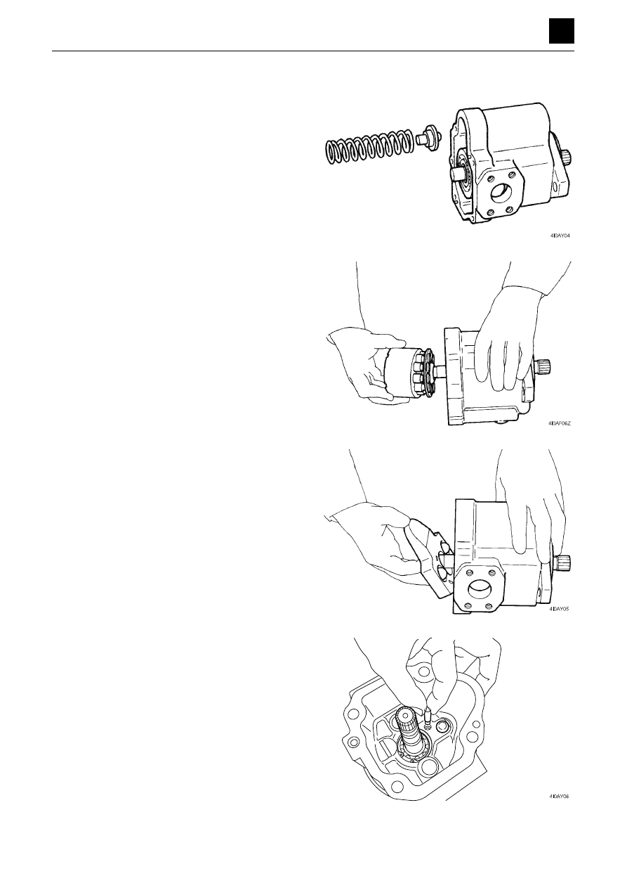
4. Remove the spring (15) and spring holder (16) from

the body S (1).

5. Remove the cylinder block (4) from the body S (1).

6. Remove the swash plate (10) and the oscillating pin

(12) from the body S (1).

7. Remove the stopper pin A (21), belleville spring (26),

and piston (19) from the body S (1).

• To avoid errors during reassembly, store these

parts in the proper order and arrangement.

8. Remove the snap ring (27) from the shaft end of the

body S (1).

DISASSEMBLY AND ASSEMBLY

HYDRAULIC PUMP

4

4

HYDRAULIC PUMP

4I0AY001

9. Remove the shaft (3) and oil seal (25) from the body

S (1).

• Tap the shaft (with the bearing attached) with a

plastic hammer to remove it.

10. Remove the spring guide (17) from the body H (2).

DISASSEMBLY AND ASSEMBLY

HYDRAULIC PUMP

5

4

HYDRAULIC PUMP

4I0AY001

Assembly

1. Insert the oil seal (25) into the body S (1).

• Make sure to use a new oil seal.
• Apply a small amount of grease to the lip on the

oil seal and around the outer circumference of the
oil seal itself.

• Insert the oil seal using the press-fitting jig A (see

the figure below), tapping it lightly with a hammer
to make it go in.

2. Insert the shaft (3) into the body S (1), and secure it

in place using the snap ring (27).

• Be careful not to damage the lip on the oil seal

while inserting the part.

3. Place the four belleville springs (26) onto the stopper

pin A (21), and insert the resulting assembly into the
body S (1).

• Be careful not to attach the belleville springs in the

wrong direction.

4. Insert the piston (19) into the body S (1).

5. Attach the oscillating pin (12) to the swash plate (10),

and attach the resulting assembly to the spherical
hole on the body S (1).

• Apply grease to the oscillating pin.

6. Insert the cylinder block assembly (4) into the body

S (1).

DISASSEMBLY AND ASSEMBLY

HYDRAULIC PUMP

6

4

HYDRAULIC PUMP

4I0AY001

7. Insert the spring (15) into the spring holder (16). Fi-

nally, insert the spherical part of the spring holder
into the hole on the swash plate.

8. Insert the spring guide (17) and O-ring (30) into the

body H (2).

9. Align the valve plate (5) with the spring pin on the

body H and attach it carefully.

• The side of the valve plate with the barbs is the

sliding surface that is to make contact with the cyl-
inder block. Make sure not to reverse it.

10. Insert the O-ring (30) and pins (22) and (34) into the

body S (1).

11. To attach the packing, line it up with the locator pin

on the body S.

• Use a new packing.

DISASSEMBLY AND ASSEMBLY

HYDRAULIC PUMP

7

4

HYDRAULIC PUMP

4I0AY001

12. Insert the two cap screws (M10×50) for temporary

assembly into the proper positions on the top side
and loosely tighten them down. Once the gap be-
tween the joining surfaces reaches 10 mm (0.39 in.),
insert the cap screws (M10×40) into the remaining
two screw positions and tighten them down.

13. Take out the cap screws for temporary assembly and

replace them with the cap screws (M10×40), and
tighten those screws down to secure the parts in
place.

Cap screws: 51.0 to 64.7 N·m (37.6 to 47.7 ft.-lb)

14. Attach the collar (40) and the coupling (39) to the

gear pump linking section of the piston pump and
then attach the O-rings (42) and (44).

15. Attach the gear pump using the two cap screws (1)

and two washers.

Cap screws: 19.6 to 23.5 N·m (14.5 to 15.2 ft.-lb)

16. To check to see if the assembly is in order, turn the

pump while holding the shaft in place loosely using a
vise.  If it does not rotate smoothly, take the assembly
apart and try again.

DISASSEMBLY AND ASSEMBLY

HYDRAULIC PUMP

8

4

HYDRAULIC PUMP

4I0AY001

Inspection and adjustments

Checking the parts

Item

Criteria

Action

Piston and cylinder block 
assembly

• When the width of the clearance (S)

between the piston and cylinder block
assembly is above 0.05 mm (0.0022
in.)

• Replace

• When there is damage, scratches, ab-

normal wear, or other problems
present on the surfaces of sliding parts

• Replace

Amount of looseness be-
tween the piston and 
shoe

• When the amount of looseness (S) be-

tween the piston and shoe is above 0.2
mm (0.0079 in.) in range

• Replace

Shaft and oil seal mount

• When the amount of wear on the shaft

and oil seal mount is 0.025 mm
(0.00098 in.) deep or more

• Replace

Valve plate

• When there are abnormal scratches

(measuring more than 0.02 mm
(0.00079 in.) in length or width), wear
or seizing on the sliding surfaces

• Repair or re-

place

Bushing

• When there is abnormal wear or harm-

ful damage on the sliding surfaces

• Replace

Seals and O-rings

• During reassembly after parts disas-

sembled

• Replace

Drive gears and driven 
gears

• When there are abnormal scratches,

wear, or flaking on tooth surfaces

• Replace

Ball bearings and needle 
bearings

• When there are abnormal scratches,

wear, or flaking on the rolling surfaces

• Replace togeth-

er with the shaft
assembly

4I0AF22Z 

S = D-d

D

d

4I0AF24Z 

e

f

1

4

Control valve

Disassembly anD assembly

4J0aX00

Control valve

Control valve

Construction

Standard

  1.  tie rod
  2.  nut
  3.  outlet housing
  4.  bucket section
  5.  boom section
  6.  right travel section
  7.  inlet housing
  8.  left travel section
  9.  arm section
10.  auxiliary section

11.  swing section
12.  switch valve
13.  slew section
14.  Dozer blade section
15.  main relief valve
16.  Port relief valve
17.  anti-cavitation valve
18.  Plug
19.  Plug

2

4

Control valve

Disassembly anD assembly

4J0aX00

Control valve

  1.  tie rod
  2.  nut
  3.  outlet housing
  4.  bucket section
  5.  boom section
  6.  right travel section
  7.  inlet housing
  8.  left travel section
  9.  arm section
10.  auxiliary section

11.  swing section
12.  switch valve
13.  slew section
14.  Dozer blade section
15.  2nd auxiliary section
16.  main relief valve
17.  Port relief valve
18.  anti-cavitation valve
19.  Plug
20.  Plug

Auxiliary 2

3

4

Control valve

Disassembly anD assembly

4J0aX00

Control valve

  1.  tie rod
  2.  nut
  3.  outlet housing
  4.  bucket section
  5.  boom section
  6.  right travel section
  7.  inlet housing
  8.  left travel section
  9.  arm section
10.  auxiliary section
11.  swing section

12.  switch valve
13.  slew section
14.  Dozer blade section
15.  2nd auxiliary section
16.  3rd auxiliary section
17.  main relief valve
18.  Port relief valve
19.  Port relief valve
20.  anti-cavitation valve
21.  Plug
22.  Plug

Auxiliary 2 + 3

4

4

Control valve

Disassembly anD assembly

4J0aX00

Control valve

Right travel section

  1.  Housing
  2.  spool
  3.  o-ring
  4.  Wiper
  5.  seal holder
  6.  spring holder
  7.  spring
  8.  screw
  9.  Cover
10.  Cap screw
11.  screw
12.  Plug
13.  Poppet
14.  spring
15.  o-ring

Left travel section

Swing section

-$,=

  1.  Housing
  2.  spool
  3.  o-ring
  4.  Wiper
  5.  seal holder
  6.  spring holder
  7.  spring
  8.  screw
  9.  Cover
10.  Cap screw
11.  screw
12.  Plug
13.  Poppet
14.  spring
15.  o-ring

  1.  Housing
  2.  spool
  3.  o-ring
  4.  Wiper
  5.  seal holder
  6.  spring holder
  7.  spring
  8.  screw
  9.  Cover
10.  Cap screw
11.  screw
12.  Poppet
13.  spring
14.  Plug
15.  o-ring
16.  o-ring

5

4

Control valve

Disassembly anD assembly

4J0aX00

Control valve

Boom section

  1.  Housing
  2.  spool
  3.  spring holder
  4.  spring
  5.  spring holder
  6.  Cover 
  7.  o-ring

  8.  Cap screw
  9.  Poppet
10.  spring
11.  Plug
12.  o-ring
13.  Poppet
14.  spring

15.  spacer
16.  backup ring
17.  Plug
18.  Poppet
19.  Cap screw
20.  o-ring
21.  anti drift valve

Slew section

  1.  Housing
  2.  spool
  3.  spring holder
  4.  spring
  5.  spring holder
  6.  Cover
  7.  o-ring
  8.  Cap screw
  9.  Poppet
10.  spring
11.  Plug
12.  o-ring
13.  o-ring
14.  Cover

6

4

Control valve

Disassembly anD assembly

4J0aX00

Control valve

Arm section

  1.  Housing
  2.  spool
  3.  Plug
  4.  orifice
  5.  Poppet
  6.  spring
  7.  Plug
  8.  o-ring
  9.  spring holder
10.  spring
11.  spring holder
12.  Cover
13.  o-ring
14.  Cap screw
15.  Poppet
16.  spring

Bucket section

  1.  Housing
  2.  spool
  3.  spring holder
  4.  spring
  5.  spring holder
  6.  Cover
  7.  o-ring
  8.  Cap screw
  9.  Poppet
10.  spring
11.  Plug
12.  o-ring
13.  Poppet
14.  o-ring
15.  Cover

Dozer blade section

  1.  Housing
  2.  spool
  3.  o-ring
  4.  Wiper
  5.  seal holder
  6.  spring holder
  7.  spring
  8.  screw
  9.  Cover
10.  Cap screw
11.  screw
12.  Poppet
13.  spring
14.  Plug
15.  o-ring

17.  Plug
18.  o-ring
19.  o-ring
20.  o-ring
21.  Cover

7

4

Control valve

Disassembly anD assembly

4J0aX00

Control valve

Main relief valve

  1.  Housing
  2.  Plug
  3.  sleeve
  4.  main poppet
  5.  Piston
  6.  needle valve
  7.  setscrew
  8.  Washer

  9.  lock nut
10.  spring
11.  spring
12.  o-ring
13.  backup ring
14.  o-ring
15.  o-ring
16.  o-ring

Switch valve

  1.  Housing
  2.  spool
  3.  spring holder
  4.  spring
  5.  spring holder
  6.  Cover
  7.  o-ring
  8.  Cap screw
  9.  Cover
10.  Filter
11.  Washer
12.  Plug
13.  o-ring

Auxiliary section

  1.  Housing
  2.  spool
  3.  o-ring
  4.  Wiper
  5.  seal holder
  6.  spring holder
  7.  spring
  8.  screw
  9.  Cover
10.  Cap screw
11.  screw
12.  Poppet
13.  spring
14.  Plug
15.  o-ring
16.  o-ring

8

4

Control valve

Disassembly anD assembly

4J0aX00

Control valve

Port relief valve

  1.  Housing
  2.  Plug
  3.  sleeve
  4.  main poppet
  5.  Piston
  6.  needle valve
  7.  spring
  8.  spring
  9.  set screw
10.  Washer

11.  lock nut
12.  o-ring
13.  backup ring
14,  o-ring
15,  backup ring
16,  o-ring
17.  o-ring
18.  spring
19.  o-ring

Anti-cavitation valve

-$)=

  1.  Plug
  2.  Poppet
  3.  spring
  4.  o-ring
  5.  backup ring
  6.  o-ring

9

4

Control valve

Disassembly anD assembly

4J0aX00

Control valve

Disassembly

For disassembly of the control valve, follow the procedure 
below. For assembly of the control valve, follow the same 
procedure as for disassembly in the reverse order.

Valve assembly

  1.  loosen the nuts (1) and remove the tie rods (2), then 

remove the sections.

    be  sure  to  apply  position  marks  to  each  section  to 

avoid mistakes during assembly.

 nut (1): 26.5 to 29.4 n·m (19.5 to 21.7 ft-lb.)

  2.  remove the o-ring.

 •  The contact surface is of a metal seal. Pay attention 

not to damage or make a dent on it.

  3.  remove the main relief valve and the port relief valve, 

and then remove the o-ring from the relief valve. 

 •  Do not disassemble unless necessary. The pressure 

value set in the valve is changed if the lock nut is 
loosened and the setscrew is turned.

 •  Do not further disassemble the port relief valve as it 

is impossible to adjust pressure after reassembly. 

 main relief valve: 74 ±5


n·m (54.6 ±3.7 ft-lb.)

 Port relief valve: 74 ±5 n·m (54.6 ±3.7 ft-lb.)

  4.  remove the anti-cavitation valve (1), and then remove 

the o-ring from the anti-cavitation valve.

 anti-cavitation valve: 74 ±5 n·m  (54.6 ±3.7 ft-lb.)

-$(=

-$(=

-$)=

-$)=

10

4

Control valve

Disassembly anD assembly

4J0aX00

Control valve

-$(=

  5.  remove the load check valve. 

a. remove the spring (3) and then the poppet (4).

  6.  remove the load check valve.

a. take out the plug (5) and spring (6) and remove the 

poppet (7).

 Plug: 29.4 n·m (21.7 ft-lb.)

 b. remove the o-ring (8) from the plug.

Manually operated section

  1.  remove the cap screws, the cover (1) and the spool 

assembly (2).

 Cap screw: 7.3 n·m (5.4 ft-lb.)

  2.  take out the seal holder and remove the wiper and the 

o-ring.

  3.  take out the screws on the spool yoke side of the sec-

tion, and then remove the seal holder, wiper ring and 
o-ring.

 •  When assembling, temporarily fasten the seal holder 

with the screws and tighten them only after confirm-
ing that the spool turns smoothly.

-$)=

-$)=

-$)=


Content      ..     7      8      9      10     ..