Takeuchi Mini Excavator TB215R (No.215000003~). Operator's Manual - page 11
 

  Index      Manuals     Takeuchi Mini Excavator TB215R (No.215000003~). Operator's Manual


Search            copyright infringement  


Content      ..     9      10      11      12     ..


Takeuchi Mini Excavator TB215R (No.215000003~). Operator's Manual - page 11


2

4

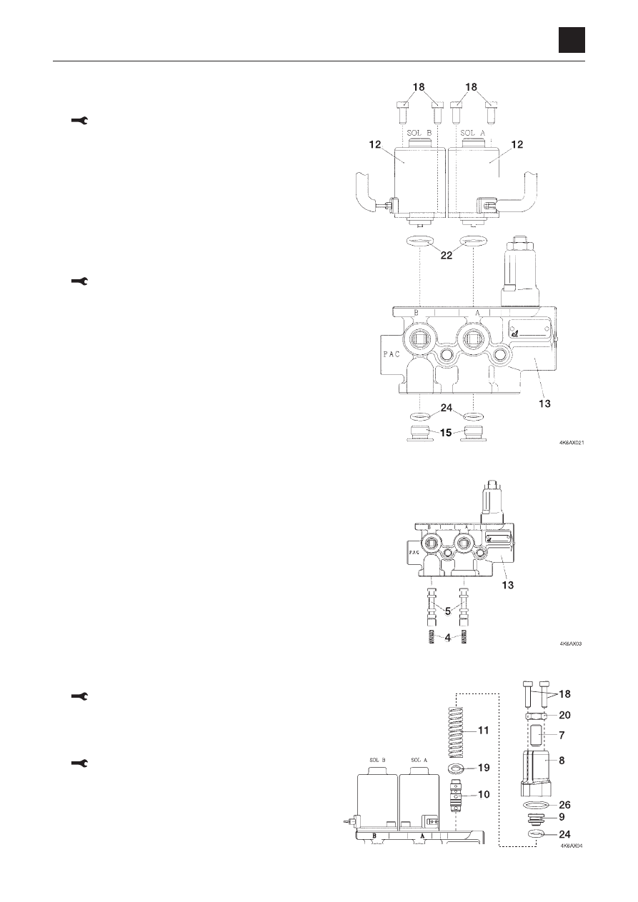
SOLENOID VALVE (LEVER LOCK)

DISASSEMBLY AND ASSEMBLY

4K6AX002

SOLENOID VALVE (LEVER LOCK)

Disassembly

Solenoid valve

  1.  Remove the cap screws (13).

 Cap screw: 3.9 N·m (2.9 ft-lb.)

 2. Take out the solenoids (12) and remove the O-rings 

(22).

 •  Place  alignment  marks  on  the  solenoids  and  the 

body for easy reassembly.

 •  Take care not to let the push rod drop out.
 •  When assembling, be sure to fit the O-rings (22) to 

the solenoids (12) before installing them on the body 
(13).

  3.  Take out the plugs (15) and remove the O-rings (24).

 Plug: 26.5 N·m (19.5 ft-lb.)

  4. Remove the springs (4) and spools (5) from the body 

(13).

Relief valve

  1.  Remove the nut (20).

 Nut: 15.7 N·m (11.6 ft-lb.)

  2.  Remove the adjust screw (7).

  3.  Remove the cap screws.

 Cap screw: 3.9 N·m (2.9 ft-lb.)

  4. Take out the cover (8) and remove the plug (9) and O-

ring (26).

  5.  Remove the O-ring (24), spring (11), washer (19) and 

plunger (10).

3

4

SOLENOID VALVE (LEVER LOCK)

DISASSEMBLY AND ASSEMBLY

4K6AX002

SOLENOID VALVE (LEVER LOCK)

Check valve

  1.  Remove the plug (3) from body (13).

 Plug: 21.0 N·m (15.5 ft-lb.)

  2.  Remove the spring (2) and the plunger (1).

  3.  Remove the O-ring (23).

  4.  Remove the plugs (16) and O-rings (25).

 Plug: 26.5 N·m (19.5 ft-lb.)

Assembly

For assembly, follow the same procedure as for disassem

-

bly in the reverse order by referring to the construction dia-
gram.

Inspection and adjustment

Checking the parts

Parts

Judgment criteria

Treatment

Coil

• When the solenoid is burned or short-circuited, or has a wire break
• Wiring short-circuit or wire break

Replace
Replace

Body

• Scratches, rust or corrosion at the sliding parts and the spool
• Scratches, rust or corrosion of the seal part in contact with the O-

ring

• Other damage considered to impair normal function

Replace
Replace

Replace

Spool

• Scratches  on  the  outer  circumference,  on  which  the  fingernails get 

caught

• Movement is not smooth.

Replace

Repair or replace

Spring

• Rust, corrosion, deformation, breakage or other notable damage

Replace

O-ring

––

Replace

DISASSEMBLY AND ASSEMBLY

SELECTOR VALVE

1

4

SELECTOR VALVE

4K8AQ00

SELECTOR VALVE

Construction

1. Body
2. Rotor
3. Lever
4. Bolt
5. O-ring
6. O-ring
7. O-ring
8. O-ring
9. Spring pin

10. Snap ring
11. Cap screw
12. Washer

DISASSEMBLY AND ASSEMBLY

SELECTOR VALVE

2

4

SELECTOR VALVE

4K8AQ00

Disassembly and Assembly

The numbers in parentheses () listed after the names of
parts in this document match the numbers used in the
construction diagrams and parts lists.

General Precautions

• Perform disassembly and assembly work in a clean

place. Provide clean containers to hold parts during
disassembly.

• Clean around the ports before disassembly. Remove

paint around connectors with a wire brush.

• Clean the disassembled parts with wash oil.
• Put alignment marks on all parts to reassemble them in

the same positions.

• After each disassembly, replace all seals and apply a

thin layer of grease to them.

• Check each part for abnormal wear or seizing. Re-

move any burrs with sandpaper.

• Do not move adjusting screws, unless absolutely nec-

essary.

Disassembly

1. Remove the bolt (4) and washer (12) from the body

(1).

2. Remove the snap ring (10).

DISASSEMBLY AND ASSEMBLY

SELECTOR VALVE

3

4

SELECTOR VALVE

4K8AQ00

3. Remove the rotor (2) with the lever (3) attached from

the body (1).

4. Remove the cap screws (11) and remove the lever

(3) from the rotor (2).

5. Remove the spring pins (9) from the body (1) and ro-

tor (2).

DISASSEMBLY AND ASSEMBLY

SELECTOR VALVE

4

4

SELECTOR VALVE

4K8AQ00

6. Remove the O-rings (5) (6) (7) (8) from the body (1)

and rotor (2).

DISASSEMBLY AND ASSEMBLY

SELECTOR VALVE

5

4

SELECTOR VALVE

4K8AQ00

Assembly

1. Install the spring pins (9) in the body (1).

• Lightly tap with a hammer.

2. Fit the O-rings (5) (6) to the body (1).

3. Install the spring pin (9) in the rotor (2).

• Lightly tap with a hammer.

4. Fit the O-rings (7) (8) to the rotor (2).

DISASSEMBLY AND ASSEMBLY

SELECTOR VALVE

6

4

SELECTOR VALVE

4K8AQ00

5. Attach the lever (3) to the rotor (2). Tighten the cap

screws (11).

Cap screw: 4.9 to 6.86 N·m

6. Install the rotor (2) to the body (1).

7. Fit the snap ring (10).

8. Attach the bolt (4) and washer (12) to the body (1).

DISASSEMBLY AND ASSEMBLY

SELECTOR VALVE

7

4

SELECTOR VALVE

4K8AQ00

Inspection and adjustment

Checking the parts

Part

Criteria

Action

O-ring

• Replace

Seal

• Replace

Spool

• Wear on the sliding surfaces is 10 μm or more than the non-sliding

surfaces.

• Scratches on the sliding surfaces
• Spool does not move smoothly. 

• Replace

• Replace
• Replace

Push rod

• Tip is worn 1 mm or more
• Scratches on the sliding surfaces

• Replace
• Replace

Plug

• Imperfect sealing due to damage

• Repair or replace

Controls

• Looseness in the pin, shaft or joint of the controls results in 2 mm

play, or more.

• Wear of the pin, shaft or joint of the controls results in 2 mm play, or

more. 

• Tighten to the specified

torque

• Replace

Casing, port 
plate

• Scratches, rust, or corrosion at the parts in sliding contact with the

spool.

• Scratches, rust, or corrosion of the part of the seal in contact with the

O-ring

• Replace

• Repair or replace

1

4

Cylinders

Disassembly anD assembly

4l0aX00

CylinDers

Cylinders

Construction

Boom cylinder

  1.  Tube
  2.  bushing
  3.  Piston rod
  4.  rod cover
  5.  bushing
  6.  rod packing
  7.  Dust seal
  8.  O-ring

  9.  backup ring
10.  O-ring
11.  Piston
12.  Piston packing
13.  Wear ring
14.  set screw
15.  ball
16.  Cushion bearing

17.  Cushion seal
18.  stopper
19.  snap ring
20.  Plug
21.  O-ring
22.  Dust seal
23.  Grease fitting
24.  Grease fitting

Arm cylinder

  1.  Tube
  2.  bushing
  3.  Piston rod
  4.  rod cover
  5.  bushing
  6.  rod packing
  7.  Dust seal

  8.  O-ring
  9.  backup ring
10.  O-ring
11.  Piston
12.  Piston packing
13.  Wear ring
14.  set screw

15.  ball
16.  Plug
17.  O-ring
18.  Dust seal
19.  Grease fitting

2

4

Cylinders

Disassembly anD assembly

4l0aX00

CylinDers

Bucket cylinder

  1.  Tube
  2.  bushing
  3.  Piston rod
  4.  rod cover
  5.  bushing
  6.  rod packing
  7.  backup ring

  8.  Dust seal
  9.  O-ring
10.  backup ring
11.  O-ring
12.  Piston
13.  Wear ring
14.  Piston packing

15.  set screw
16.  ball
17.  Plug
18.  O-ring
19.  Dust seal
20.  Grease fitting
21.  Grease fitting

Dozer blade cylinder

  1.  Tube
  2.  bushing
  3.  Piston rod
  4.  rod cover
  5.  bushing
  6.  rod packing

  7.  Dust seal
  8.  O-ring
  9.  backup ring
10.  O-ring
11.  Piston
12.  Piston packing

13.  Wear ring
14.  set screw
15.  ball
16.  Dust seal

3

4

Cylinders

Disassembly anD assembly

4l0aX00

CylinDers

Swing cylinder

  1.  Tube
  2.  bushing
  3.  Piston rod
  4.  rod cover
  5.  bushing
  6.  rod packing
  7.  backup ring
  8.  Dust seal

  9.  O-ring
10.  backup ring
11.  O-ring
12.  backup ring
13.  O-ring
14.  Cushing ring
15.  spacer
16.  stopper

17.  Piston
18.  Piston packing
19.  Wear ring
20.  set screw
21.  ball
22.  Cushion bearing
23.  Dust seal
24.  Grease fitting

4

4

Cylinders

Disassembly anD assembly

4l0aX00

CylinDers

special tools

Unit: mm

Installation jig B

Quantity: 1
material: s45C

Sliding jig C

Quantity: 1
material: sTKm13C

Fitting jig D

Quantity: 1
material: nylon

Corrective jig E

Quantity: 1
material: sTKm13C

a

b

C

D

e

boom

35

45

54

5

35

arm

35

45

54

5

35

bucket

30

40

49

5

30

blade

30

40

49

5

30

swing

30

40

49

5

30

a

b

C

D

e

F

boom

60.5

58.3

40

20.8

12.3

20

arm

60.5

58.3

40

20.8

12.3

20

bucket

50.5

48

30

10.8

12.3

20

blade

60.5

58.3

40

20.8

12.3

20

swing

60.5

58.3

40

20.8

12.3

20

a

b

C

D

boom

65

61

57

53

arm

65

61

57

53

bucket

55

51

47

43

blade

65

61

57

53

swing

65

61

57

53

a

b

boom

75

60

arm

75

60

bucket

65

50

blade

75

60

swing

75

60

5

4

Cylinders

Disassembly anD assembly

4l0aX00

CylinDers

disassembly

Cylinder assembly

  1.  Keep  the  cylinder  in  a  level  position  by  securing  the 

clevis of the tube in a vise and placing a wooden sup-
port under the other end.

  2.  Drain the remaining hydraulic oil from the cylinder.

 •  Move the piston rod slowly to prevent the hydraulic 

oil from spurting out.

  3.  Disengage the anti-rotation lock of the rod cover.

 •  Since the anti-rotation lock is built into the cylinder 

tube, take care not to damage the tube when disen-
gaging the lock.

  4.  loosen the rod cover.

 •  Pull out the piston rod approximately 200 mm (7.9 

in.) beforehand.

 •  Cover the piston rod to protect it from dents.

  5.  Pull out the piston rod assembly from the tube.

 •  Pull it out straight so as not to damage the sliding 

surface.

Piston rod assembly

  1.  secure the piston rod assembly in a level position.

4LAA07Z

4LAA08Z

4LAA09Z

4LAA10Z

6

4

Cylinders

Disassembly anD assembly

4l0aX00

CylinDers

  2.  remove the piston assembly.

a. Take out the setscrew (1) and remove the ball (2).

 •  The setscrew (1) is caulked in two places with a 

punch. Grind off the caulked portions with a hand 
drill.

b. Remove the piston assembly (3).

c. Pull  out  the  cushion  bearing  (4).  (Boom  cylinder, 

swing cylinder)

<Only for boom cylinder (c to f)>

c. Remove the snap ring (4).

 •  When removing, lightly tap the ring with a plastic 

hammer while taking care not to damage the pis-
ton rod or cushion bearing.

d. Remove the stopper (5) (double-split).

 •  The  stopper  (5)  can  be  removed  by  sliding  the 

cushion bearing (6) to the piston rod side.

e. Remove the cushion ring (6).
f.  Remove the cushion seal (7).

<Only for swing cylinder>

 g. Remove the cushion bearing (8).

  3.  remove the rod cover assembly.

4LAA13Z

7

4

Cylinders

Disassembly anD assembly

4l0aX00

CylinDers

4LAA16Z

10

11

Piston

  1.  Remove the wear rings (10).

 •  Spread the wear ring just enough to disengage it in 

axial direction.

  2.  remove the piston packing from the piston.

Rod cover

  1.  Remove the O-rings (20) and (21) and the backup ring 

(22) from the outer diameter section of the rod cover.

<Only for swing cylinder>

  2.  remove the cushion ring.

a. Remove the stopper (13).
b. Remove the spacer (14).
c. Remove the cushion ring (12).

  3.  remove the rod packing.

a. Remove the rod packing (15).
b. Remove  the  backup  ring  (16).  (Bucket  cylinder, 

swing cylinder)

/$&=


Content      ..     9      10      11      12     ..