Takeuchi Mini Excavator TB215R (No.215000003~). Operator's Manual - page 13
 

  Index      Manuals     Takeuchi Mini Excavator TB215R (No.215000003~). Operator's Manual


Search            copyright infringement  


Content      ..     11      12      13      14     ..


Takeuchi Mini Excavator TB215R (No.215000003~). Operator's Manual - page 13


DISASSEMBLY AND ASSEMBLY

TRAVEL MOTOR

9

4

TRAVEL MOTOR

4M0AX00

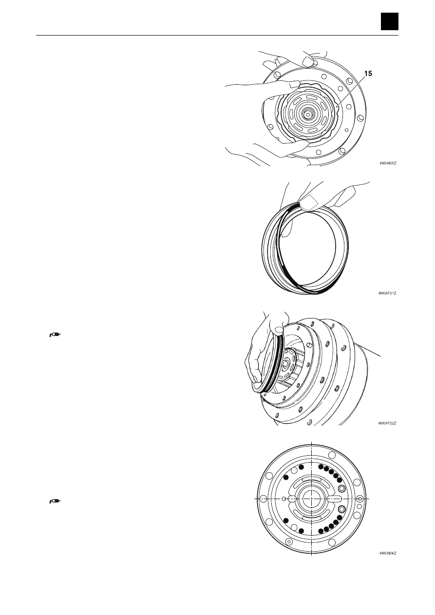
20. Insert the center disc (15) into the groove on the

flange holder.

21. Attach the two O-rings and two backup rings to the

brake piston.

• Attach the O-rings on the inside and then attach

the backup rings on the outside.

22. Attach the brake piston assembly to the flange hold-

er.

Apply grease to the O-rings, and make sure that
the seal material does not get caught in the
parts.

23. Attach the valve plate to the flange holder, and insert

the springs into the spring holes.

• The symbols “

z

” in the figure indicate the installa-

tion positions of the springs.

• Install the valve plate so that its copper surface

faces the cylinder block.

Apply grease to the valve plate and springs.
Avoid dropping them.

DISASSEMBLY AND ASSEMBLY

TRAVEL MOTOR

10

4

TRAVEL MOTOR

4M0AX00

24. Fill the flange holder with 100 ml (3.4 fl.oz) hydraulic

oil, and align the valve body with the flange holder.

25. Secure the hydraulic motor in a vise, and tighten the

screws.

Screw: 28.4 to 30.4 N·m (20.9 to 22.4 ft.-lb)

• Insert an aluminum plate or the like between the

motor and the vise to prevent the outer surface of
the valve body from becoming damaged.

Reduction gears

1. Attach the floating seat (17) and the O-ring to the

flange holder.

Apply grease to the O-ring.

2. Insert the inner race (18) of the bearing and the steel

balls (19) with retainers into the flange holder.


DISASSEMBLY AND ASSEMBLY

TRAVEL MOTOR

11

4

TRAVEL MOTOR

4M0AX00

3. Fit the O-ring to the seal ring and then attach them to

the housing.

• Align the seal ring pin with the pin hole on the

housing.

Apply grease to the O-ring.

4. Attach the housing, and insert the hydraulic motor.

• Tighten the housing and the hydraulic motor

flanges with a C clamp or a hydraulic press.

5. Insert the steel balls (19) with retainers of the bearing

and the inner race (18) into the flange holder.

6. Insert the snap ring.

DISASSEMBLY AND ASSEMBLY

TRAVEL MOTOR

12

4

TRAVEL MOTOR

4M0AX00

7. Place the rings, thrust washers, planet gears B1, and

needles on the pins.

• Be sure to attach the ring (20) in the correct direc-

tion. The side with the chamfered internal diame-
ter must be on the motor side.

8. Attach the thrust washer, and secure it in place with

the snap rings.

• Do not spread the snap ring open more than nec-

essary.

• Insert the snap ring with the edge facing the cov-

er.

9. Insert the sun gear S1 into the carrier 2, and secure

it in place with a snap ring.

10. Insert the thrust washers, planet gears B2, needles,

and thrust washers into carrier 2, and secure them in
place with a snap ring.

DISASSEMBLY AND ASSEMBLY

TRAVEL MOTOR

13

4

TRAVEL MOTOR

4M0AX00

11. Insert the carrier 2 assembly into the housing.

12. Attach the O-ring to the housing.

13. Place the ring on the cover.

Apply grease.

14. Add 330 ml (11.2 fl.oz) of lubricant.

DISASSEMBLY AND ASSEMBLY

TRAVEL MOTOR

14

4

TRAVEL MOTOR

4M0AX00

15. Attach the cover to the housing.

• Align the notch on the housing with the drain plug

hole.

16. Attach the snap ring to secure the cover in place.

• Set a flat head screwdriver against the edge of the

snap ring to hammer it in around its circumfer-
ence.

17. Attach the O-ring to the plug, and insert it into the

cover.

Plug: 46 to 51 N·m (33.9 to 37.6 ft.-lb)

DISASSEMBLY AND ASSEMBLY

TRAVEL MOTOR

15

4

TRAVEL MOTOR

4M0AX00

Inspection and adjustments

Use limit for parts

Part

Item to check

Criteria

Action

Floating seal

Sliding surface

If there are abnormal scratches, wear, or seizure 
on the surface

Replace

Angular bearing

Rolling surface

If there are abnormal scratches, or flaking on the 
ball or race

Replace

Planet gear

Gear tooth surface

If there are abnormal scratches, wear or flaking of 
the tooth surfaces (if pitting covers 10% or more of 
the area engaging with the tooth surface).

Replace

Inner race

Rolling surface

If there are abnormal scratches, wear, or flaking 
on the rolling surface

Replace

Needle

Needle surface

If there are abnormal scratches, wear, or flaking 
on the surface

Replace

Thrust washers

Sliding surface

If there are abnormal scratches, wear, or seizure 
on the surface

Replace

Housing, sun 
gear, drive gear

Gear tooth surface

If there are abnormal scratches, wear or flaking of 
the tooth surfaces (if pitting covers 10% or more of 
the area engaging with the tooth surface).

Replace

Thrust plate

Sliding surface

If there are abnormal scratches, wear, or seizure 
on the surface

Replace

O-rings

Replace

Shaft

Oil seal surface

If there are abnormal scratches, wear, or seizure 
on the surface

Replace

Ball bearing

Sliding surface

If there are abnormal scratches, or flaking on the 
ball or race

Replace

Oil seal

Replace

Swash plate

Surface of the sliding 
part with the piston 
assembly

If there are abnormal scratches ((0.02 mm (0.0008 
in.) or more), wear, or seizure on the surface

Replace

Cylinder block

Cylinder block-to-pis-
ton assembly clear-
ance

0.04 mm (0.002 in.) or more

Replace

Sliding surface with 
the valve plate

If there are abnormal scratches (0.02 mm (0.0008 
in.) or more), wear, or seizure on the surface

Repair with a lapping 
tool (#1000) or re-
place

Piston assembly

Piston assembly-to-
cylinder block clear-
ance

0.04 mm (0.002 in.) or more

Repair with a lapping 
tool (#1000) or re-
place the cylinder 
block and piston as-
sembly together

Sliding surface with 
the swash plate

If there are abnormal scratches (0.02 mm (0.0008 
in.) or more), wear, or seizure on the surface

Play of piston shoe

0.04 mm (0.002 in.) or more

Valve plate

Sliding surface with 
the cylinder block

If there are abnormal scratches (0.02 mm (0.0008 
in.) or more), wear, or seizure on the surface

DISASSEMBLY AND ASSEMBLY

TRAVEL MOTOR

16

4

TRAVEL MOTOR

4M0AX00

Valve body

Sliding surface with 
the spool

If there are abnormal scratches, wear, or seizure 
on the surface

Replace both the 
valve body and spool

Spool

Sliding surface with 
the valve body

If there are abnormal scratches, wear, or seizure 
on the surface

Sliding surface with 
the check valve

If there are abnormal scratches, wear, or seizure 
on the surface

Replace both the 
spool and check 
valve

Check valve

Sliding surface with 
the spool

If there are abnormal scratches, wear, or seizure 
on the surface

Spool and seat sur-
faces

If there is contact with the seat along the entire cir-
cumference

Part

Item to check

Criteria

Action

DISASSEMBLY AND ASSEMBLY

SLEW MOTOR

1

4

SLEW MOTOR

4N0AX00

SLEW MOTOR

Construction

Hydraulic motor

1. X-ring

12. Bearing housing

23. Snap ring

34. Pin

2. O-ring

13. Flange mounting

24. Snap ring

35. Valve housing

3. O-ring

14. Pinion gear

25. Rear bearing

36. Ball

4. Shaft face seal

15. Plug

26. Socket bolt

37. Plug

5. Inner face seal

16. Break piston

27. Gerolor

38. Spring

6. Outer face seal

17. Ring

28. Drive gear

39. Plug

7. O-ring

18. Snap ring

29. Valve plate

40. Bolt

8. O-ring

19. Friction disc

30. Valve drive gear

41. Collar

9. O-ring

20. Center disc

31. Valve

10. O-ring

21. Spring

32. Balancing ring

11. O-ring

22. Front bearing

33. Spring

DISASSEMBLY AND ASSEMBLY

SLEW MOTOR

2

4

SLEW MOTOR

4N0AX00

Brake valve

1. Plunger

2. Pinion

3. Spring

4. Timer orifice

5. Damper orifice

DISASSEMBLY AND ASSEMBLY

SLEW MOTOR

3

4

SLEW MOTOR

4N0AX00

Disassembly and assembly

General precautions

• Perform disassembly and assembly work in a clean

place. Provide clean containers to hold parts during
disassembly.

• Before disassembly, clean around the ports and re-

move coating or thread-locking compound on the
joints with a wire brush.

• Clean disassembled parts with dedicated cleaning oil.
• Apply hydraulic oil on the sliding surfaces and thin lay-

er of grease on the seals before assembly.

• Replace seals with new ones after each disassembly.
• Check each part for abnormal wear or seizing. Re-

move any burrs with sandpaper.

Disassembly

1. Take out the socket bolts, and remove the break

valve.

• Place the shaft downward, and secure the flange

section in place with a vice before starting disas-
sembling.

2. Take out the bolts, and remove the valve housing.

3. Take out the valve housing, and remove the balanc-

ing ring (5) and valve (6).

• Make sure not to lose the spring (7) and the pin (8)

for the balancing ring.

DISASSEMBLY AND ASSEMBLY

SLEW MOTOR

4

4

SLEW MOTOR

4N0AX00

4. Remove the valve plate and the valve drive gear.

5. Remove the gerolor.

6. Remove the drive.

7. Take out the socket bolts, and remove the flange

mounting.

• Do not disassemble the rear bearing unless nec-

essary.

DISASSEMBLY AND ASSEMBLY

SLEW MOTOR

5

4

SLEW MOTOR

4N0AX00

8. Remove the spring from the flange mounting.

9. Remove the brake piston.

10. Remove the ring.

11. Remove the center disc (20), the friction disc (19),

and the plate.

DISASSEMBLY AND ASSEMBLY

SLEW MOTOR

6

4

SLEW MOTOR

4N0AX00

12. Remove the snap ring.

13. Remove the pinion gear.

• Pull out the shaft assembly with a press using a

support.

• Do not disassemble the ball bearing and collar

unless necessary.

14. Remove the X-ring from the bearing housing.

15. Remove the plug, spring, and ball from the valve

housing.

DISASSEMBLY AND ASSEMBLY

SLEW MOTOR

7

4

SLEW MOTOR

4N0AX00

Assembly

1. Insert the X-ring into the bearing housing.

2. Insert the shaft into the bearing housing.

• Using a support, press-fit the shaft with a press.

3. Attach the snap ring to secure the front bearing in

place.

4. Insert the center disc (20) and the friction disc (19)

alternately in this order.

• Insert the disks in the correct order.

DISASSEMBLY AND ASSEMBLY

SLEW MOTOR

8

4

SLEW MOTOR

4N0AX00

5. Fit the O-rings to the inner part and outer part of the

ring and then insert the ring into the bearing housing.

6. Fit the O-ring to the piston and then insert them into

the housing.

7. Fit the O-ring to the flange mounting, and insert the

spring.

• Apply grease to the spring, and avoid dropping it.

8. Attach the flange mounting to the bearing housing.

• Attach the flange mounting so that the drain port

T is positioned as shown in the figure below.


Content      ..     11      12      13      14     ..