Takeuchi Mini Excavator TB215R (No.215000003~). Operator's Manual - page 15
 

  Index      Manuals     Takeuchi Mini Excavator TB215R (No.215000003~). Operator's Manual


Search            copyright infringement  


Content      ..     13      14      15      16     ..


Takeuchi Mini Excavator TB215R (No.215000003~). Operator's Manual - page 15


5

5

Overall machine

TroubleshooTing

5b0AX00

overAll mAchine

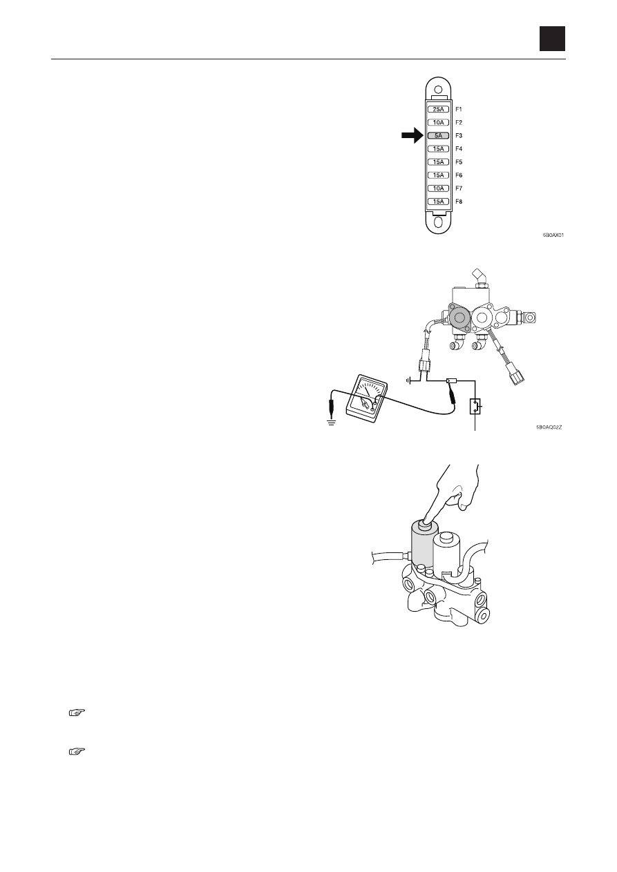
  2.  check the fuse

    check the fuse in the power supply circuit that oper-

ates the pilot solenoid valve.

  3.  check the limit switch

    Turn the limit switch on, by moving the lever stand to 

the driving position.

    Then check the voltage at the lever lock solenoid valve 

with a tester.

    If there is voltage, the switch works normally.

  4.  check the lever lock solenoid valve

    Check according to the following procedure.

a.  Turn the starter switch to the on position.

b. Lightly press down the protruding part on the sole

-

noid valve.

c. move the lever stand to turn on the limit switch.

d. If  you  feel  vibration  under  your  fingers  when  the 

spool is moved and the circuit is switched, the sole-
noid valve is normal.

  5.  check the pilot relief valve

    measure the relief pressure of the pilot relief valve.

 •  If  the  measured  value  is  within  specifications,  the 

valve is normal.

 “2. Service data, Performance criteria”

  6.  check the pilot valve

 “4. Disassembly and assembly, Pilot valve”

%$,=

1

5

Traveling

TroubleshooTing

5c0AX00

TrAveling

Traveling

No travel is possible

1

check  the  supply  pres-
sure  for  the  travel  lever 
lock cylinder

normal

2

Check the linkage

Faulty

repair  or  replace  the  faulty 

part(s)

normal

3

check the travel lever lock 
cylinder

Faulty

replace  the  travel  lever  lock 
cylinder

  1.  check the supply pressure for the travel lever lock 

cylinder

    Disconnect  the  piping  connecting  the  solenoid  valve 

and the travel lever lock cylinder from the cylinder side. 

Fit the pressure gauge to the hose just disconnected to 

measure the pilot pressure.

 •  Fit the plug to the cylinder port from which the hose 

was disconnected.

 •  If the measured value is within the specifications, the 

pressure is normal.

 “2. Service data, Performance criteria”

  2.  check the linkage

    Check the operation of the travel lever lock cylinder (1) 

and the slide plate (2). 
 •  Cylinder stroke......10 mm (0.4 in.)
 •  The  operations  of  the  lever  lock  cylinder  and  the 

slide  plate  are  checked.  Also,  the  fixing  bolts  and 

nuts should be checked for the looseness.

  3.  The travel lever lock cylinder is faulty

    it is not possible to disassemble the travel lever lock 

cylinder. replace the cylinder with a new one.

&$,=

2

5

Traveling

TroubleshooTing

5c0AX00

TrAveling

Right or left travel is impossible

1

check  the  operation  of 
actuators  other  than  of 
the travel motor

normal

2

check  the  spool  opera-
tion

Faulty

Repair or replace the housing 

block

normal

3

Check the linkage

Faulty

Adjust, repair or replace

normal

4

check the swivel joint

Faulty

repair  or  replace  the  swivel 
joint

normal

5

check  the  counter  bal-
ance valve

Faulty

repair or replace the counter 
balance valve

normal

6

check the travel motor

Faulty

repair  or  replace  the  travel 
motor

  1.  check the operation of actuators other than of the 

travel motor.

    If the right or left travel is impossible, operate each ac

-

tuator  of  the  devices  listed  in  the  table  on  the  right. 

if operation is faulty, inspect the main relief valve and 
piston pump.

  2.  check the spool operation

 •  Spool stroke......7 mm (0.3 in.)
 •  If the spool is sticking, try to take it out.

    if  it  can’t  be  taken  out  or  is  scratched,  replace  the 

housing block.

    One cause of the spool not operating properly could 

be that the return spring installation bolt is loose.

Problem

lever to 

operate

Device to check

relief valve

Pump

Right travel

boom

r1

P1

left travel

Arm

r2

P2

*$)=

3

5

Traveling

TroubleshooTing

5c0AX00

TrAveling

  3.  check the linkage

    To check the linkage, remove the R pin (2) and pin (3) 

which  connect  the  spool  and  the  yoke  (1),  and  then 
inspect the yoke (1) movement.

  4.  check the swivel joint

 •  Disconnect the hose connecting the swivel joint and 

the counter balance valve from the counter balance 

valve. Fit the pressure gauge to the hose just dis

-

connected.

 •  Operate the travel lever and measure the pressure.
 •  If  the  measured  value  is  within  specifications,  the 

swivel joint is normal.

 “2. Service data, Performance criteria”

  5.  check the counter balance valve

 •  If neither forward nor reverse travel is possible, the 

spool  (1)  of  the  counter  balance  valve  could  be 
sticking in the neutral position.

 •  If  either  forward  or  reverse  travel  is  possible,  the 

spool (1) of the counter balance valve could be stick

-

ing in a position other than the neutral position.

 •  Remove the counter balance valve plug (2) and push 

the spool (1) with a finger. If it moves smoothly about 
6 mm (0.2 in.), the counter balance valve is normal.

  6.  check the travel motor

 “4. Disassembly and assembly, Travel motor”

&$)=

&$)=

*$)=

4

5

Traveling

TroubleshooTing

5c0AX00

TrAveling

Right or left travel speed decelerates, causing the machine to veer to one side

1

Is  the  veering  within 

specs?

Within specs

Problem is caused by the 

combination of devices

normal

out-of-specs

2

check  the  crawler  belt 

tension.  check  for  for-

eign matter caught in the 

crawler belt

Faulty

Adjust to the specified crawler 
tension  and  remove  the  for-

eign matter

normal

3

check  the  spool  opera-
tion

Faulty

Repair or replace the housing 

block

normal

4

Switch the discharge hos

-

es between the pumps

Veering is changed to the opposite 

side

• 

repair or replace the pumps

• 

replace  the  hydraulic  oil  or 
the filter

No change

5

Test by switching the main 

relief valves

Veering  is  changed 

to the opposite side check  the  main  relief 

valve

repair  or  replace  the  faulty 
main relief valve

No change

6

check the swivel joint

Faulty

repair  or  replace  the  swivel 
joint

normal

7

check  the  counter  bal-
ance valve

Faulty

repair or replace the counter 
balance valve

normal

8

Travel motor is faulty

repair  or  replace  the  travel 
motor

5

5

Traveling

TroubleshooTing

5c0AX00

TrAveling

  1.  is the veering within specs?

    If  the  veering  is  within  specifications,  the  machine  is 

normal. Problem is caused by the combination of de

-

vices.

 “2. Service data, Performance criteria”

  2.  check the crawler tension

 “2. Service data, Performance criteria”

  3.  check the spool operation

 “No travel is possible, 2. Check the linkage.”

  4.  Switch the discharge hoses between the pumps

    Switch  the  discharge  hoses  between  the  pumps  P1 

and P2. If the veering direction is changed to the op

-

posite side, the pumps are faulty.

 •  Disassemble and check the pump

 “4. Disassembly and assembly, hydraulic pump”

  5.  Test by switching the main relief valves

    Switch the main relief valves between the right travel 

circuit and the left travel circuit, and operate the ma-

chine. If the veering is changed to the opposite side, 

one of the main relief valves is faulty.

 •  Check the main relief valve

 “5.  Troubleshooting,  Overall  machine,  All  sys

-

tems working, but insufficient force, 4. Check 

the main relief valve.”

  6.  check the swivel joint

 “Right  or  left  travel  is  impossible,  4.  Check  the 

swivel joint”

  7.  check the counter balance valve

    check to see if the spool of the counter balance valve 

moves smoothly.

 “Right  or  left  travel  is  impossible,  5.  Check  the 

counter balance valve”

  8.  check the travel motor

 “4. Disassembly and assembly, Travel motor”

&$)=

6

5

Traveling

TroubleshooTing

5c0AX00

TrAveling

2nd speed travel is not possible

1

Check the gear pump (4)

Faulty

Repair  or  replace  the  gear 

pump

normal

2

check the fuse

Faulty

replace the fuse

normal

3

check  the  2nd  speed 
switch, harness and con-
troller

Faulty

replace the 2nd speed switch, 
harness and controller

normal

4

check the 2nd speed so-
lenoid valve

Faulty

repair  or  replace  the  2nd 
speed solenoid valve

normal

5

check the swivel joint

Faulty

repair  or  replace  the  swivel 
joint

normal

6

check  the  2nd  speed 
control valve

Faulty

repair  or  replace  the  2nd 
speed control valve

1.  check the gear pump (4)

    Check the gear pump (4) that supplies hydraulic pres

-

sure for the 2nd speed switching.

 “2. Service data, Performance criteria”
 “5. Troubleshooting, Piston pump”

    Also, check the line filter for clogging, and clean it as 

necessary.

  2.  check the fuse

    check  the  fuse  in  the  power  supply  circuit  that  acti-

vates the 2nd speed solenoid valve.

7

5

Traveling

TroubleshooTing

5c0AX00

TrAveling

  3.  check the 2nd speed switch, harness and control-

ler

a. Press the switch to turn it on. Use a tester to check 

if a voltage is applied.

   The switch is normal if a voltage is applied.

b. check the harness continuity.
c. check the switch.
d. check the controller.

 “2. Service data, Electric circuit diagram”

  4.  check the 2nd speed solenoid valve

a.  Turn the starter switch to the on position.

b. Lightly press down the protruding part on the sole

-

noid end. 

c. move the lever stand to turn on the limit switch.

d. If  you  feel  vibration  under  your  fingers  when  the 

spool is moved and the circuit is switched, the sole-
noid valve is normal.

  5.  check the swivel joint

    Disconnect  the  hose  connecting  the  swivel  joint  and 

the 2nd speed control valve from the 2nd speed con-

trol valve. Fit the pressure gauge to the hose just dis

-

connected, and then turn on the 2nd speed switch.

 •  Supply pressure: 3.4 MPa (493 PSI)

  6.  2nd speed control valve is faulty

    check  if  the  spool  of  the  2nd  speed  control  valve  is 

sticking or if foreign matter is caught in the spool.

 “4. Disassembly and assembly, Travel motor”

&$,=

&$)=

5C0AQ03Z

1

5

Slewing

TroubleshooTing

5D0AX00

sleWing

Slewing 

No slewing is possible

1

check  the  operation  of 
actuators  other  than  of 
the slew motor

normal

2

check the pilot valve

Faulty

repair  or  replace  the  pilot 
valve

normal

3

check  the  spool  opera-
tion

Faulty

Repair or replace the housing 

block

normal

4

check the slew pressure

Pressure too low

Adjust the pressure of the 
slew relief valve

Adjust to the set pressure

normal

Pressure does not rise

repair  or  replace  the  relief 
valve

5

check the slew motor

Faulty

repair  or  replace  the  slew 
motor

normal

Slew bearing is faulty

replace

  1.  check the operation of actuators other than of the 

slew motor

    Determine if only the slew motor is faulty by checking 

the operation of actuators for the devices listed in the 

table on the right. If one of them is faulty, check the 
main relief valve and the hydraulic pump (main).

 “5. Troubleshooting, Overall machine, All systems 

working, but insufficient force”

lever to operate

Device to check

relief valve

Pump

blade

R3

P3

2

5

Slewing

TroubleshooTing

5D0AX00

sleWing

  2.  check the pilot valve

    Disconnect the hose connecting the pilot valve and the 

control valve (slew block) from the control valve. Fit the 
pressure gauge to the hose just disconnected.
 •  Insert a plug into the control valve port.
 •  Operate the lever (slew) and measure the pressure.
 •  If the pressure is between 0 and 3.4 MPa (0 to 493 

PSI) depending on the lever angle, the pilot valve is 

normal.

  3.  check the spool operation

    Disconnect the hose connecting the control valve (slew 

block) and the slew motor from the control valve. Fit 
the pressure gauge to the discharge port on the con

-

trol valve.

 •  Operate the lever (slew) and measure the pressure.
 •  If the measured value is as below, the spool is nor

-

mal.

   Supply pressure: 20.0 MPa (2901 PSI)

  4.  check the slew pressure

    Measure  the  pressure  at  the  right  and  left  slew  relief 

valves.

 •  If  the  measured  value  is  within  specifications,  the 

slew pressure is normal.

 “2. Service data, Performance criteria”

    if the pressure adjustment is possible, the adjustment 

of the slew relief valve is faulty. if the pressure adjust-
ment is not possible, the slew relief valve is faulty.

  5.  check the slew motor

    Separate the slew motor (1) from the turntable (2), and 

then try turning the turntable (2).
 •  Does not turn.....The slew bearing (3) is faulty.
 •  Turns

..................

The slew motor (1) is faulty.

 “4. Disassembly and assembly, Travel motor”

'$,=

'$,=

'$,=

3

5

Slewing

TroubleshooTing

5D0AX00

sleWing

Slew right or left is not possible

1

check the pilot valve

Faulty

repair  or  replace  the  pilot 
valve

normal

2

check  the  spool  opera-
tion

Faulty

Repair or replace the housing 

block

normal

3

check  the  slew  relief 
valve

Faulty

repair or replace the  slew re-
lief valve

normal

4

The slew motor is faulty

repair  or  replace  the  slew 
motor

  1.  check the pilot valve

    it  is  likely  that  only  the  pilot  valve  spool  on  the  side 

where slewing is not possible is faulty.

 “No slewing is possible, 2. Check the pilot valve”

  2.  check the spool operation

    it is likely that the spool does not move in the direction 

in which slewing is not possible.

 “No slewing is possible, 3. Check the spool op

-

eration”

  3.  check the slew relief valve

    Switch between the left and right slew relief valves. If 

slewing becomes possible, the relief valve is faulty.

  4.  The slew motor is faulty

 “4. Disassembly and assembly, slew motor”

'$,=

4

5

Slewing

TroubleshooTing

5D0AX00

sleWing

Slewing is slow or lacks force

1

is  the  time  needed  for 

slewing within specs?

Within specs

normal

slow

2

check the pilot valve

Faulty

repair  or  replace  the  pilot 
valve

normal

3

check  the  spool  opera-
tion

Faulty

Repair or replace the housing 

block

normal

4

check the slew pressure

Pressure too low

Adjust the slew relief valve 
pressure

Adjust to set pressure

normal

Pressure does not rise

repair  or  replace  the  relief 
valve

5

check the slew motor

Faulty

repair  or  replace  the  slew 
motor

normal

Slew bearing is faulty

replace

  1.  is  the  time  needed  for  slewing  within  specifica-

tions?

 “2. Service data, Performance criteria”

  2.  check the pilot valve

 “No slewing is possible, 2. Check the pilot valve”

  3.  check the spool operation

 “No slewing is possible, 3. Check the spool op

-

eration”

  4.  check the slew pressure

 “No slewing is possible, 4. Check the slew pres

-

sure”

  5.  check the slew motor

 “4. Disassembly and assembly, slew motor”

5

5

Slewing

TroubleshooTing

5D0AX00

sleWing

The machine slews, but overruns a lot when slewing stops, or slewing cannot be stopped

1

is  the  amount  of  overrun 

when slewing stops with

-

in specs?

Within specs

normal

out-of-specs

2

check the pilot valve

Faulty

repair  or  replace  the  pilot 
valve

normal

3

check  the  spool  opera-
tion

Faulty

Repair or replace the housing 

block

normal

4

check the slew pressure

Pressure too low

Adjust the slew relief valve 
pressure

Adjust to set pressure

Pressure does not rise

repair  or  replace  the  relief 
valve

  1.  is the amount of overrun when slewing stops within 

specs?

 “2. Service data, Performance criteria”

  2.  check the pilot valve

    check if the spool of the pilot valve returns to the neu-

tral position when the operation lever (slew) is released 
after  operation.  Disconnect  the  hose  connecting  the 
pilot valve and control valve (slew block) from the con

-

trol valve. Fit the pressure gauge to the hose just dis

-

connected.

 •  Operate the lever (slew) and then release it to read 

the pressure gauge.

 •  If the pressure is zero, the pilot valve is normal.

'$,=

6

5

Slewing

TroubleshooTing

5D0AX00

sleWing

  3.  check the spool operation

    Check if the spool of the control valve (slew block) re

-

turns to the neutral position when the operation lever 

(slew) is released after operation. Disconnect the hose 
connecting the control valve (slew block) and the slew 
motor from the control valve. Fit the pressure gauge to 
the discharge port on the control valve.
 •  Operate the lever (slew) and then release it to read 

the pressure gauge.

 •  If the pressure is zero, the spool is normal.

  4.  check the slew pressure

 “No slewing is possible, 4. Check the slew pres

-

sure”

'$,=

7

5

Slewing

TroubleshooTing

5D0AX00

sleWing

When stopped on a slope, the upperstructure cannot maintain its posture

1

is  the  slew  spontaneous 
drop within specs?

Within specs

normal

out-of-specs

2

check the slew pressure

Pressure too low

Adjust  the  relief  valve 
pressure of the slew brake 
valve

Adjust to set pressure

normal

Pressure does not rise

repair or replace the slew re-
lief valve

3

check the slew motor

Faulty

repair  or  replace  the  slew 
motor

  1.  is the slew spontaneous drop within specs?

 “2. Service data, Performance criteria”

  2.  check the slew pressure

 “No slewing is possible, 4. Check the slew pres

-

sure”

  3.  check the slew motor

 “4. Disassembly and assembly, slew motor”

TROUBLESHOOTING

BOOM

1

5

BOOM

5G0AX001

BOOM

The boom cylinder does not move

1. Check the operation of actuators other than of the

boom cylinder.

Determine if only the boom cylinder is faulty by
checking the operation of actuators for the devices
listed in the table on the right. If one of them is faulty,
check the main relief valve and the hydraulic pump
(main).

“5. Troubleshooting, Overall machine, All sys-
tems working, but insufficient force”

1

Check the operation of 
actuators other than of 
the boom cylinder.

Normal

2

Check the pilot valve.

Faulty

Repair or replace the pilot 
valve.

Normal

3

Check the spool opera-
tion.

Faulty

Repair or replace the housing 
block.

Normal

4

Test by replacing the port 
relief valve.

Problem solved

The port relief valve is 
faulty.

Repair or replace the port re-
lief valve.

Normal

5

Check the boom cylinder.

Faulty

Repair or replace the boom 
cylinder.

Lever to operate

Device to check

Relief valve

Pump

Right travel

R1

P1


Content      ..     13      14      15      16     ..