Takeuchi Hydraulic Excavator TB175W (S/N 17540001~). WORKSHOP MANUAL - page 12
 

  Index      Manuals     Takeuchi Hydraulic Excavator TB175W (S/N 17540001~). WORKSHOP MANUAL


Search            copyright infringement  


Content      ..     10      11      12      13     ..


Takeuchi Hydraulic Excavator TB175W (S/N 17540001~). WORKSHOP MANUAL - page 12


HYDRAULIC UNITS

CONTROL VALVES

IV-51

TB175W

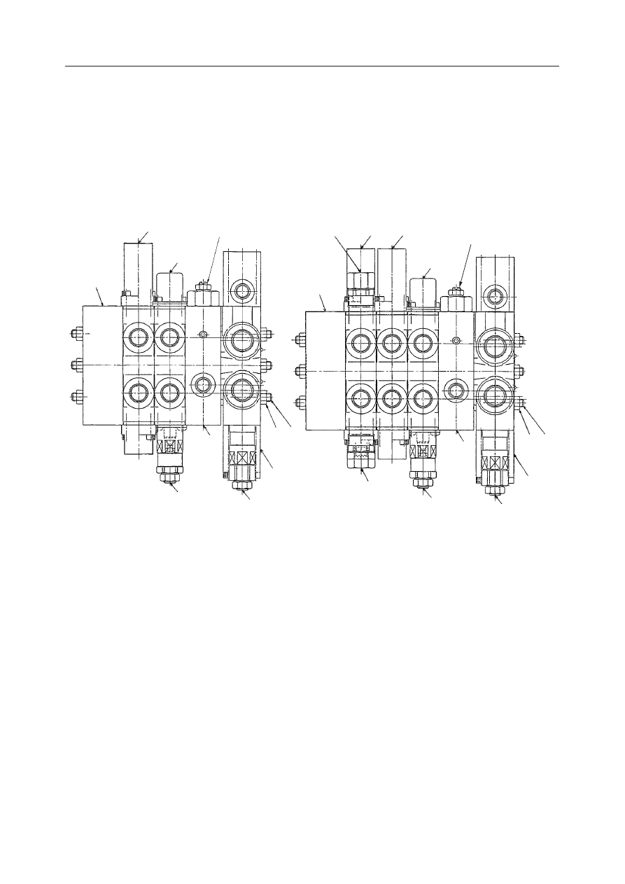
CONTROL VALVES (3-SECTION/4-SECTION)

CONSTRUCTION

  1. Nut
  2. Tie Rod
  3. Slew Flow Control Section Assembly
  4. Dozer Blade Section Assembly
  5. Slew Section Assembly
  6. Outlet Housing
  7. Main Relief Valve
  8. Port Relief Valve
  9. Spacer Section
10. Slow Slew Speed Adjusting Valve
11. Auxiliary Section Assembly
12. Port Relief Valve

W2D215E

6

6

11

5

4

5

4

9

8

7

3

1 2

10

12

10

3-Section

4-Section

12

8

9

7

3

1 2

HYDRAULIC UNITS

CONTROL VALVES

IV-52

TB175W

Slew Flow Control Section

  1. Screw
  2. Sleeve
  3. Pin
  4. O-ring
  5. Piston
  6. Spring Holder
  7. Spring
  8. Cover
  9. O-ring
10. Cover
11. O-ring
12. Cap Screw
13. O-ring

Dozer Blade Section

  1. Cover
  2. Screw
  3. Spring Holder
  4. Spring
  5. Cover
  6. Load Check Valve
  7. Spring
  8. O-ring
  9. O-ring

  1. Screw
  2. Spring Holder
  3. Spring
  4. Cover
  5. Seal Holder
  6. Load Check Valve
  7. Spring
  8. Wiper
  9. O-ring
10. O-ring

Slew Section

L3D251

1

5

8

9

5

4

3

2

10 7

6

L3D252

8

7

6

1

3

4 2

3

9

9

5

HYDRAULIC UNITS

CONTROL VALVES

IV-53

TB175W

Outlet Housing

  1. Filter
  2. Orifice

Spacer Section

  1. Plug
  2. Adjusting Screw
  3. Nut
  4. O-ring
  5. O-ring
  6. O-ring

L3D253

1

2

L3D254

6

3

4

1

2

5

  1. Cover
  2. Screw
  3. Spring Holder
  4. Spring
  5. Cover
  6. Load Check Valve
  7. Spring
  8. O-ring
  9. O-ring

Auxiliary Section

W2D217

1

2

3

3

4

5

6

7

8

9

9

HYDRAULIC UNITS

CONTROL VALVES

IV-54

TB175W

11. Lock Nut
12. O-ring
13. Backup Ring
14. O-ring
15. Backup Ring
16. O-ring
17. O-ring
18. Wave Washer
19. O-ring

  9. Lock Nut
10. Spring
11. Spring
12. O-ring
13. Backup Ring
14. O-ring
15. O-ring
16. O-ring

Main Relief Valve

  1. Housing
  2. Plug
  3. Sleeve
  4. Main Poppet
  5. Seat
  6. Needle Valve
  7. Adjusting Screw
  8. Washer

  1. Housing
  2. Adjusting Screw
  3. Poppet
  4. Spring
  5. Lock Nut
  6. O-ring
  7. O-ring

Port Relief Valve

C4D205

2

5

7

1

7

4

6

3

  1. Housing
  2. Plug
  3. Sleeve
  4. Main Poppet
  5. Piston
  6. Needle Valve
  7. Spring
  8. Spring
  9. Adjusting Screw
10. Washer

Port Relief Valve

W2D216

1

2

3

4

5

6

7 8

9

10

11

12

13

14

15

16

HYDRAULIC UNITS

CONTROL VALVES

IV-55

TB175W

OPERATION

When the Spool is in the Neutral Position

When the control valve spool is not moving, hydrau-
lic oil flows through the center bypass passage (1) and
then through the tank passage (T) in the arrow direc-
tion, returning to the tank.

When the Spool is Actuated

Explanation is given for the case where the spool is
moved to the right.
When the spool (2) is moved to the right, the center
bypass passage (3) is closed and hydraulic oil entering
from the pump passes through the load check valve
(5) from the parallel passage (4), flowing from the A
port to the actuator. On the other hand, oil returning
from the B port flows through the tank circuit (T) and
returns to the tank.

Load Check Valve

A load check valve (5) is included in each section
except the travel (right, left) sections.
This valve prevents oil from flowing backward due to
the load pressure (C) from the actuator port during
switching of the spool.

HYDRAULIC UNITS

CONTROL VALVES

IV-56

TB175W

Slew Flow Control Function

This function switches the quantity of hydraulic oil
flowing to the slew motor to change the slewing speed
between normal and slow. It also keeps the flow to the
motor steady even when the supply pressure changes
during slow speed slewing.

Normal speed mode

When there is no pilot pressure at port FC, spool (1),
push rod (2) and piston (3) are positioned at the left
side by spring (4). In addition, pre-choke pressure P1
is led to the left side of spool (1) through pilot hole (5)
and post-choke pressure P2 is led to the right side of
spool (1) through pilot hole (6). At this time, all the oil
supplied from port P3 flows to the slew motor.

Slow speed mode

When the pilot pressure reaches port FC, piston (3)
moves to the right side, push rod (2) and spool (1) also
move, and the difference between pre-choke pressure
P1 and post-choke pressure P2 at spool (1) works to
maintain a constant pressure (PC). Part of the hydrau-
lic oil supplied from port P3 passes through the
control orifice (7) and flows to the slew motor, and the
remaining oil flows to tank port T2. The pressure at
port P3 (PS) at this time increases, and when the flow
increases, the difference in pressure between P1 and
P2 increases, so spool (1) moves to the right side, the
control orifice (7) is choked, the pressure difference
[P1 – P2] is kept at PC, and the flow to the slew motor
does not increase.

Inversely, when the pressure (PS) at port P3 de-
creases, the difference in pressure between P1 and P2
decreases, so spool (1) is moved to the left side by
spring (4) until the pressure difference reaches PC and
orifice (7) opens, so the flow to the slew motor does
not decrease.
In this way, only a specific quantity of the oil supplied
flows to the slew motor even when the supply pres-
sure changes, the remaining being release to tank port
T2. This makes it possible to slew in the slow speed
mode with a slow flow.

HYDRAULIC UNITS

CONTROL VALVES

IV-57

TB175W

Main Relief Valve

A main relief valve is mounted between the pump
circuit and tank circuit of each inlet housing and
serves to maintain the circuit pressure at the set value.

When the Relief Valve is NOT Operating

When the pressure in the circuit is low with respect to
the set value, the relief valve maintains equilibrium.
Hydraulic oil from the pump passes through the
orifice from chamber (C) and arrives at the spring
chamber (D) and the needle valve (1). On the other
hand, forces F and F1 are acting in the respective
arrow directions on both sides of the main poppet (2).
F = P 

×

 A

Fl = P 

×

 A1

P: Pressure

A, A1: Cross Sectional Area

Since the cross sectional area of A is less than that of
A1, the main poppet (2) is pushed by the force
“F1 - F” to the seat surface on the left side.

When the Relief Valve is Operating

If the circuit's pressure becomes greater than the set
value of the spring (3), the needle valve (1) is pushed
to the right by hydraulic pressure and oil flows to the
tank passage (T). When this happens, a pressure
differential is generated between the two ends of
orifice of the main poppet (2), and this hydraulic
pressure pushes the main poppet toward the right. As
a result, the pressurized oil in the circuit flows to the
tank passage.
This operation maintains the pressure in the circuit at
the set value.

F1

S3F611

F

A

A1

C

2

D

1

S3F612

T

3

2

1

HYDRAULIC UNITS

CONTROL VALVES

IV-58

TB175W

Port Relief Valve

A port relief valve is located between the actuator port
and the tank circuit and when abnormal pressure due
to shock pressure or external pressure generated when
the actuator port is suddenly blocked by the spool or
when there is an overload occurs, these valves act to
protect the actuator.

Relieving Operation

When the pressure in the circuit is low with respect to
the set value, the relief valve is maintained at equilib-
rium. Pressure from the pump passes from chamber B
to the orifice in piston (4), then reaches chamber C and
the needle valve (5). On the other hand, forces F and
F1 are acting in the arrow directions on both sides of
the main poppet (6).
F = P 

×

 A

F1 = P 

×

 A1

P: Pressure

A, A1: Sectional Area

Since the sectional area of A is less than that of A1, the
main poppet (6) is pushed by the force “F1-F” to the
seat surface on the left side.

If the pressure in the circuit becomes higher than the
force of the spring (7), the needle valve (5) is pushed
to the right by hydraulic pressure, opening. Oil then
flows around the circumference of the needle valve
(5) and passes through the slits, flowing into the tank
passage (T).

When the needle valve (5) opens, the pressure drops
on the back side of the piston (4), pushing the piston
(4) to be pushed to the right, seating with the needle
valve (5). This shuts off the flow of hydraulic oil to the
rear of the main poppet (6). As a result, the pressure
in chamber C on the inside drops.

Compared to the chamber B side, the pressure in
chamber C is low and there is no equilibrium in
pressure. For this reason, the main poppet (6) opens
and pressurized oil flows to the tank passage (T).

HYDRAULIC UNITS

CONTROL VALVES

IV-59

TB175W

Suction Operation

When the cylinder is operated at high speed, and the
supply of oil cannot keep up with it, creating a vacuum
in chamber B, oil is supplied from the tank side,
preventing the occurrence of cavitation.
When the pressure in chamber B is lower than the
pressure in the tank passage (T), the differences in the
sectional areas A and A1 cause the main poppet (6) to
open. Thus, sufficient oil from the tank passage (T)
enters chamber B, filling the empty space.

For Auxiliary

The figure at right shows when hydraulic pressure
arrives at chamber A from the actuator port. If this
pressure becomes stronger than the set value of the
spring (1), it pushes the poppet (2) to the right side and
pressurized fluid from the actuator port flows to the
tank passage.

HYDRAULIC UNITS

CONTROL VALVES

IV-60

TB175W

DISASSEMBLY AND ASSEMBLY

General Cautions

• Since all parts in control valves are precision

machined, carry out disassembly and assembly
operations in a clean place.

• Before disassembly, clean the outside surfaces

around the valves.

• Clean all disassembled parts in cleaning solvent.

Use a lint free cloth, or air dry the parts.

• Apply hydraulic oil to sliding surfaces and apply a

thin coating of grease to seals when assembling
them.

• Replace all seals with new ones each time the

valves are disassembled.

• Spools and section bodies are specially selected for

a precise fit. Therefore, if any damage is found in
either of these parts, replace the section assembly
as a unit.

• Be sure to number each section and spool to avoid

mistakes during assembly.

• Do not turn adjusting screws if not required.

Following is an explanation of the control valve
disassembly procedure.
Follow the procedure used to disassemble the control
valve in reverse order when reassembling it.
• Before disassembly, number each section and spool.

Disassembly
Valve Assembly

1. Loosen the nuts and remove the tie rods, then

remove the sections.

Nut: 19.0 N·m

2. Remove the O-ring.

• The mating surfaces are metal seals, so be

careful not to scratch, bruise or otherwise dam-
age them.

3. Remove the main relief valves and the port relief

valves, then remove the O-rings from the relief
valves.
• Do not disassemble the relief valves unless it is

necessary.

• When using a spanner or adjustable wrench, be

sure to attach it in the place shown in the figure
at right.

Relief valve: 68~78.5 N·m

G4D223

HYDRAULIC UNITS

CONTROL VALVES

IV-61

TB175W

4. Remove the load check valve.

• Remove the spring (3), then remove the poppet

(4).

Manually Operated Section

1. Remove the cap screws (5), the cover (6) and the

spool assembly (7).

Cap screw: 7.3 N·m

2. Loosen the screw (8) from the spool assembly (7).

Screw: 5.2 N·m

3. Remove the spring holder (9), spring (10), and

spring holder (9).

HYDRAULIC UNITS

CONTROL VALVES

IV-62

TB175W

4. Remove the seal holder (12), then remove the

backup ring (13) and O-ring (14).

5. Remove the screws on the spool yoke end side of

the section, then remove the seal holder, backup
ring and O-ring.

Screw: 2.5 N·m

Pilot Operated Section

1. Take out the cap screw (5) and remove the cover

(15), then remove the O-ring (16) from the cover
(15).

Cap screw: 7.3 N·m

2. Remove the spool from the section.

K3D217

HYDRAULIC UNITS

CONTROL VALVES

IV-63

TB175W

3. Take out the screw (17) and remove the spring

holder (18), spring (19) and spring holder (18).

Screw: 4.9 N·m

4. Take out the cap screws (5) and remove the cover

(21).

5. Remove the O-ring (16) from the cover (21).

Cap screw: 7.3 N·m

Disassembling the Slew Flow Control Block

1. Remove cap screws (1), then remove cover (2),

spring (3), spring holder (4) and spool (5).

Cap screw: 9.8 N·m

2. Remove O-ring (6) from cover (2).

3. From the opposite side of the block, remove cap

screws (7), then remove cover (8), piston (9), pin
(10) and sleeve (11).

Cap screw: 9.8 N·m

4. Remove O-ring (12) from cover (8).

5. Remove O-ring (13) from sleeve (11).

K3D219

5

21

16

HYDRAULIC UNITS

CONTROL VALVES

IV-64

TB175W

Main Relief Valve

1. Remove the plug (1) from the housing (2).

Plug: 49~54 N·m

2. Remove the O-ring (3) from the plug (1).

3. Remove the sleeve (4) from the plug (1) and

remove the spring (5) and main poppet (6) from
the sleeve (4).

4. Remove the O-ring (7) and backup ring (8) from

the seat (9).

5. Remove the lock nut (10), washer (11) and adjust-

ing screw (12) from the plug (1), then remove the
O-ring (13) from the adjusting screw (12).
• During assembly, after installing the adjusting

screw (12), lock the lock nut (10) temporarily,
then tighten it after adjusting the pressure.

Lock nut: 27~31 N·m

6. Remove the spring (14) and needle valve (15).

W2D218

1

2

3

W2D219

4

5

6

7

8

1

9

W2D220

1

10

11

12

13

14

15

HYDRAULIC UNITS

CONTROL VALVES

IV-65

TB175W

INSPECTION AND ADJUSTMENT

Checking the Parts

Adjusting the Main Relief Valve Pressure

“II. Specifications, Standards for Judging Per-
formance”

Parts

Judgment Criteria

Treatment

• Replace

• Replace

• Replace

• Replace

• Replace

Housing,
Section Body

• Scratches, rust, corrosion of the portion which slides

against the spool.

• Scratches, rust, corrosion of the seal pocket portion of

the part that enters the spool.

• Scratches, rust, corrosion of the port seal portion which

is in contact with the O-ring.

• Scratches, rust, corrosion of the seal portion of the relief

valve, etc.

• Other damage which could be a hindrance to correct

function.

• Scratch marks like being clawed around the outer cir-

cumference sliding portion.

• Scratches on the portion that slides against the seals on

both ends.

• Spool not operating smoothly.

• Imperfect sealing due to damage to the valve or spring.
• Does not catch, but operates lightly when inserted in the

section body and operated.

• Rust, corrosion, deformation, breakage or other marked

damage to the spring, holder or cover.

• Oil leaking to the outside.
• Rust, corrosion or deformation of the seal holder.

• External rust, damage.
• Damage to valve seat contact surface.
• Damage to poppet contact surface.
• Abnormality in the spring.
• O-rings, backup rings, seals

• Replace

• Replace

• Repair or replace.

• Repair or replace.
• Normal

• Replace

• Repair or replace.

• Replace
• Replace
• Replace
• Replace
• As a rule, all these

should be replaced.

Spool

Load Check Valve

Around Springs

Around Spool Seal

Main Relief Valve,
Port Relief Valve

HYDRAULIC UNITS

CONTROL VALVES

IV-66

TB175W

L3D255

84.4

A

1

2

Adjusting The Slow Slew Speed Adjusting
Valve

The slow slew speed can be adjusted in the range of
38% to 71%. The slow slew speed has been set to 71%
at the factory. (The right figure shows the setting at the
factory.)
• Adjustable distance A: 3 mm

1. Loosen the lock nut (2) and turn the set screw (1)

to fine adjust the slew speed.
Turning to the left will reduce the speed.
Turning to the right will increase the speed.

2. Upon completion of the adjustment, tighten the

lock nut while holding down the set screw to
prevent it from turning.

3. Operate the valve again to confirm that the set

screw is stable.

TROUBLESHOOTING

“IV-48~49”


Content      ..     10      11      12      13     ..